
Abstract
As a new type of manufacturing equipment, redundant hybrid machines have the theoretical advantage over the traditional serial machines in efficiently processing large structural parts with high material removal ratio and complex parts with curved surfaces. In order to solve the accuracy problem of the redundantly actuated spatial parallel module of a five-axis hybrid machine, an improved kinematic calibration method is proposed in this article. First, different from error modeling for the corresponding non-redundant parallel module, the geometric error model of the redundantly actuated spatial parallel module considers the deformations at active joints caused by actuation redundancy as an error source. Then, the applicable error model is developed using projection technique to remove the need of active joints’ stiffness measurement or modeling. Later, the practical error model is derived from model reduction method to avoid using additional sensors or gratings. Finally, three forms of relative measurement and step identification are adopted for the calibration work, and the bilinear interpolation compensation function is introduced to ensure the calibration effect. On this basis, the kinematic calibration of the redundantly actuated spatial parallel module is conducted. The max position errors are reduced from original −0.192 to 0.075 mm after RM1 and SI1, and then further reduced to 0.014 mm after bilinear interpolation compensation, while the max orientation errors are reduced from −0.017° and 0.249° to −0.005° and −0.007° after RM2 and SI2, and RM3 and SI3, respectively. A contrasting experiment is also carried out with the previous method for the corresponding non-redundant parallel module. As a result, the proposed method shows better convergence value and speed in identifying error parameters, and therefore the effectiveness and efficiency of the proposed method for the redundantly actuated spatial parallel module are validated.
Keywords
Introduction
With the development of spaceflight, aviation, navigation, and so on industries, the demands of high-efficiency machining of large structural parts with high material removal ratio and complex parts with curved surfaces increase rapidly, while the traditional serial machines gradually fail to meet the requirements due to their high-inertia moving components and poor orientation adjustment capabilities. To this point, new types of machining equipment are in urgent need.
As the counterpart of serial mechanisms (SMs), parallel mechanisms (PMs) have theoretical advantages of large stiffness/mass ratio, quick dynamic response, and high flexibility due to their multi-closed-loop architectures.1,2 Therefore, PMs are generally employed as a great complement of SMs to improve performance when applied to manufacturing industry.3–5 In light of this, hybrid machines, which comprise both serial and parallel modules, are becoming the tendency when creating new types of machining equipment. Currently, the practically built hybrid machines include ECOSPEED, 6 TRICEPT, 7 EXECHON, 8 VERNE, 9 XNZ2415, 10 SPKM165,11,12 and so on, and some of them have been proven to have higher efficiency in milling large aerospace parts and turbine blades. 6
In spite of these merits, PMs still suffer from limited workspaces, complex singularities, and deformations of kinematic chains, 13 and these disadvantages restrict the PMs’ promotions. A feasible way to overcome these drawbacks is considered to be redundancy, which can be realized in two ways: (1) actuation redundancy 14 and (2) kinematic redundancy. 13 Till now, there have been several practical cases among hybrid machines. For example, XNZ2415 has the kinematically redundant (KR) mode of XNZ755, 13 and SPKM165 has the redundantly actuated (RA) mode of RASPET150. 15
As an unavoidable issue, accuracy problem is also critical for the redundant PMs, and kinematic calibration is still the economical and efficient approach to handle it.16,17 Moreover, kinematic calibration is actually one of the challenging issues for the redundant PMs, 18 because they would be over-constrained and produce restrained deformations in the kinematic chains by the generated constraint forces if the geometric errors exist, while this situation would not happen in the non-redundant modes.
In general, the calibration methods can be classified into external calibration and self-calibration according to the means of data acquisition. 19 Since the restrained deformations at joints can be detected by the internal sensors directly, self-calibration is naturally eligible for calibrating redundant PMs. One of the first study attempting to calibrate a 3-degree-of-freedom (3-DoF) redundant PM just adopted this method in 1994. 20 From then on, this method has been applied to different configurations.21–24 However, the actual output poses are estimated not measured in self-calibration, which makes it hard to ensure the identification accuracy of error parameters. What’s worse, because the tool poses relative to external references, like workpiece coordinate system, cannot be calibrated, self-calibration is regarded not suitable for machine tools. 19
Aiming at accurately error modeling for external calibration of the redundant PMs, in 2004, Jeong et al. 25 analyzed and summarized three relationships that dominate the error propagation in the structures: (1) relationship between torque and torsional deflections at active joints (AJs), (2) relationship among actual deflections of joints by geometric constraint, and (3) relationship of constraint torque equilibrium. On this basis, the error model of a 2-DoF RA planar PM (RAPPM) was formulated, and the external calibration was done with a laser ball bar. Note that the stiffness of AJs was experimentally measured to meet relationship (1), whereas it is quite difficult to implement, especially after assembly. Alternatively, without stiffness measurement, Ecorchard et al. 26 first proposed to establish the elasto-geometrical models for RA PMs by considering the stiffness modeling of links and joints in 2010, and calibrated a 2-DoF RAPPM with two actuated redundant chains. Similarly, Ding et al. 27 developed a general error modeling method for RA PMs with limb stiffness matrixes based on Lie-group theory and screw theory. Meanwhile, Jiang et al. 28 and Li et al. 29 extended this thought to the calibration of over-constrained planar and spatial translational PMs, respectively, by taking into account the mechanical models and the force-induced link deformations. Nevertheless, all these studies are under the assumption of slender links and ideal joints. If the limb structures of the redundant PMs are complicated, the stiffness modeling procedures would become very tough.
In order to avoid the stiffness measurement or modeling, a new thought of separating and removing the impacts of restrained deformations at AJs was developed from projection technique, which is a commonly used technique in signal processing to extract specific signals from the disturbs, clutters, or noises. 30 In 2007, Zhang et al. 31 first introduced this technique into the error modeling, and thus solved the calibration problem of the sensor zero positions of a 2-DoF RAPPM. Besides, by correcting the encoder index errors of AJs, this technique was further used to eliminate the contradicting control forces inside some 2-DoF RAPPMs.32,33 On the foundation of the research studies by Jeong et al. 25 and Zhang et al., 31 Jeon et al. 34 proposed a new integrated calibration method for RA PMs in 2010. The error propagation formula was developed to eliminate the effect of the force redundancy by projecting the error term associated with the restrained deformations onto the orthogonal complementary space of its coefficient matrix, so that there was no need to know the stiffness of AJs anymore. Accordingly, external measurement device and internal sensors were simultaneously used to detect the required error data. The 2-DoF RAPPM studied by Jeong et al. 25 was calibrated again with this method, but no direct comparison was made since different measurement device was employed this time. Also, a 3-DoF RAPPM was calibrated to testify the applicability of this method. However, no spatial PMs are included, and the necessity of mounting additional sensors or gratings on AJs makes it hard to apply, especially to those existing spatial PMs.
In summary, there is no universal calibration method fit for all kinds of redundant PMs. One appropriate calibration method depends on the PM’s configuration, dimension, structure, and application comprehensively. Consequently, in many cases that the redundant PMs didn’t satisfy the conditions of the above methods, the calibration works continued to use the previous methods for their corresponding non-redundant PMs (CNRPMs).15,35–37
Recently, a new five-axis hybrid machine has been assembled completely, which possesses the same kinematics with RASPET150, 15 but more than three times as large as the prototype in each dimension. In addition, all the links and many other components of its parallel module, a 3-DoF RA spatial PM (RASPM), are topological optimized for heavy-loading manufacturing, making the structure compact but complex. On this account, the available calibration methods for the redundant PMs cannot be utilized directly. To solve the accuracy problem of the hybrid machine, this article proposes an improved kinematic calibration method for the RASPM. It is featured by a new error modeling procedure combining projection technique and model reduction method, which is generally used to rationally simplify the relevant models in practical engineering works for some purposes.38,39 In this case, the stiffness measurement and modeling are avoided, as well as the usage of additional sensors or gratings.
The remainder of this article is organized as follows. Section “Geometric error modeling” describes the composition and mobility of the five-axis hybrid machine, and establishes the geometric error model of the RASPM. Section “Proposed calibration method” introduces the proposed calibration method for the RASPM. The executing procedures, experimental results, and comparisons with the previous method are presented in section “Kinematic calibration experiment.” At last, conclusions are drawn in section “Conclusion.”
Geometric error modeling
Description of the five-axis hybrid machine
The overview and the three-dimensional (3D) model of the five-axis hybrid machine are shown in Figure 1(a) and (b), respectively. Six motors with fixed axes are mounted on this machine totally. Figure 1(c) presents its kinematic scheme, revealing a 1T1R-type (T: translational DoF and R: rotational DoF) serial module as well as a parallel module with three kinematic chains and four AJs. Figure 1(d) presents the way to analyze the mobility of the parallel module using Grassmann line geometry and line-graph method, 40 where blue lines represent for rotational motion, blue arrows for translational motion, red lines for force constraint, and red arrows for moment constraint. As a result, the constraint and motion line graphs are shown in Figure 1(e), which prove that the parallel module performs a 2T1R-type motion with one redundant actuation.
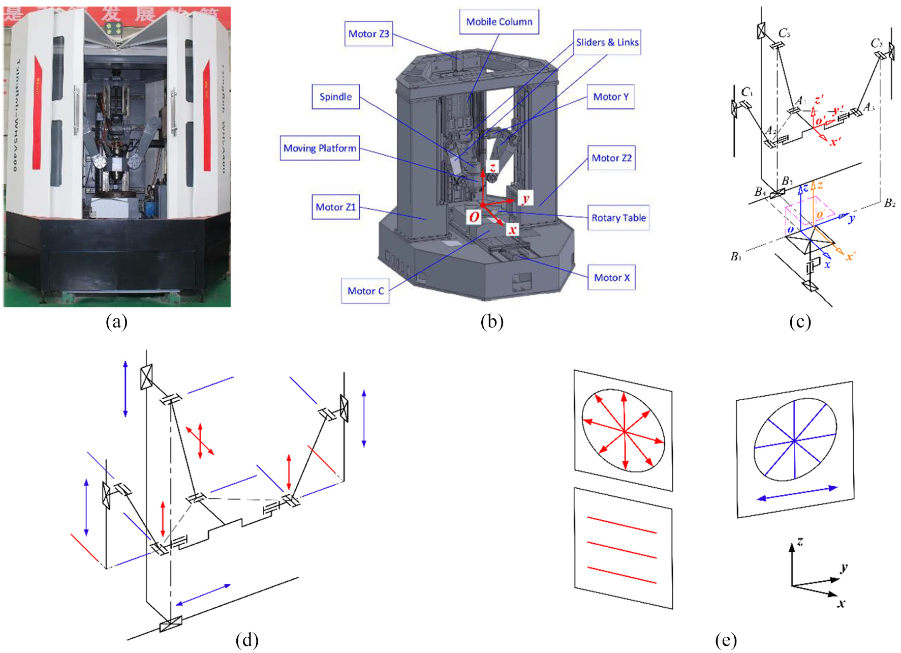
The five-axis hybrid machine: (a) overview; (b) 3D model; (c) kinematic scheme; (d) motions and constraints in the RASPM; and (e) constraint and motion line graphs for the RASPM.
Actually, 2T1R-type parallel module plus 1T1R-type serial module, short for P{2T1R}&S{1T1R} (P{}: parallel module and S{}: serial module), is a new type of 3T2R-type hybrid machines. Unlike P{1T2R}&S{2T} (ECO SPEED) 6 or P{3T}&S{2R} (TRICEPT, 7 EXECHON, 8 VERNE), 9 this type splits the two rotational DoFs into different modules, so that the side effects from the coupling rotations can be avoided, and a high rotational capability of P{2T1R} can be achieved. 40 Therefore, the studied hybrid machine benefits from the theoretical advantage in manufacturing applications.
Modeling of the geometric errors
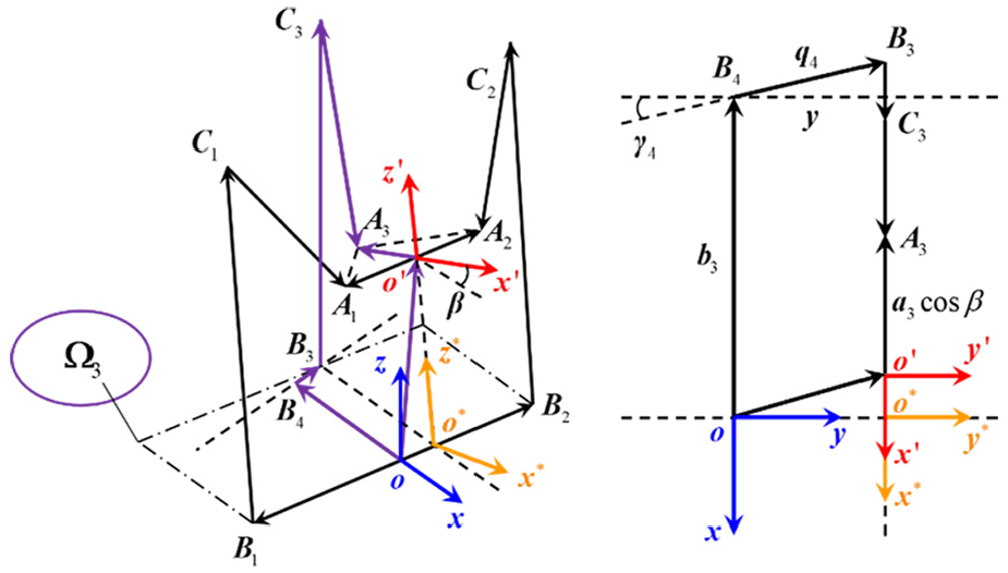
The kinematics vector diagram of the RASPM is shown in Figure 2. Points
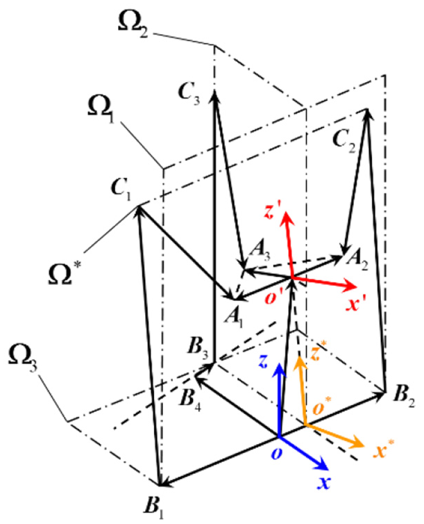
Kinematic vector diagram of the RASPM.
Generally, the geometric errors of a PM can be classified into two categories. One varies with the pose of the end-effector, and is marked with the prefix
For a
Because of the structural over-constraint, the joint motions can’t match up with each other ideally when the abovementioned errors exist in redundant PMs, and constraint forces will take place accordingly. To reach the equilibrium of force redundancy, restrained deformations will be generated in return to make the geometric relationships stable again. Based on the fact that AJs are generally designed to be less stiff than PJs to absorb the kinematic errors,
41
restrained deformations can be thought to be concentrated at AJs. Obviously, this error source is different from
As observed in Figure 2, all the kinematic vectors and geometric relationships adhere to three planes:
The denotations of the dimension parameters.
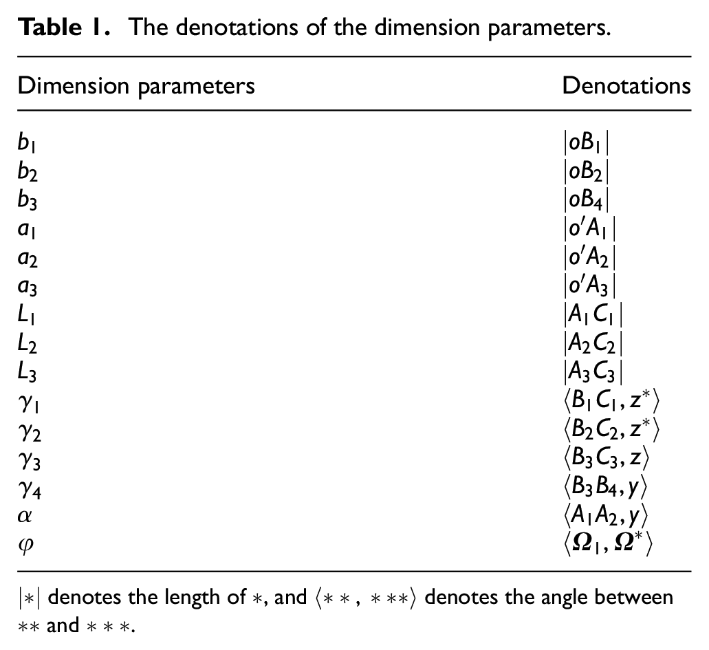
|*| denotes the length of *, and 〈**,***〉 denotes the angle between ** and ***.
Modeling in
As shown in Figure 2, vector

where
Besides, the relationship between

Differentiate both sides of equation (2), and achieve

where
Then, substitute equation (1) into equation (3), merge the similar terms, and obtain
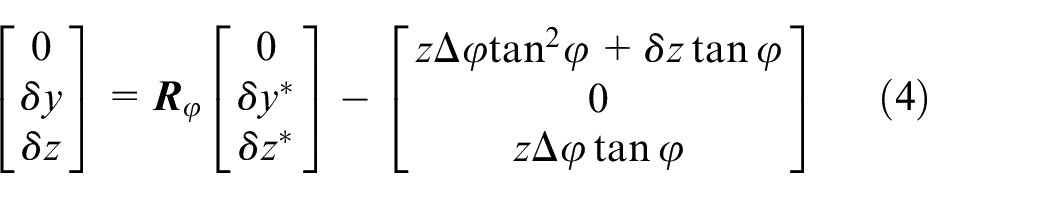
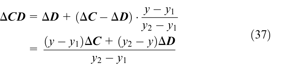
Subsequently, isolate


where
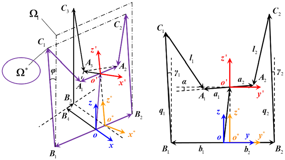
Kinematics vector diagram in
Differentiate both sides of equations (5) and (6), remove the high-order infinitesimal terms, and yield
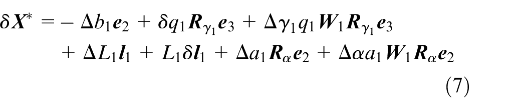
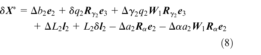
where
It is known that

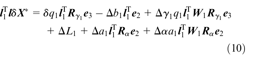
Multiply both sides of equation (7) with
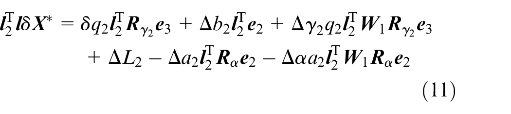
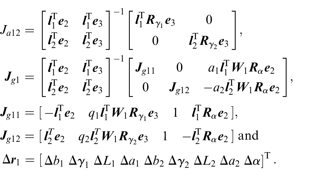
After that, unite equations (10) and (11), and the error propagation formula developed in
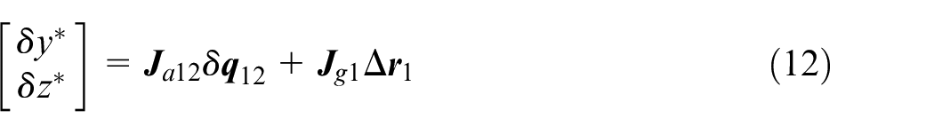
where
Modeling in
As shown in Figure 2, vector

Isolate
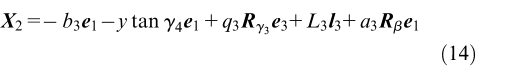
where
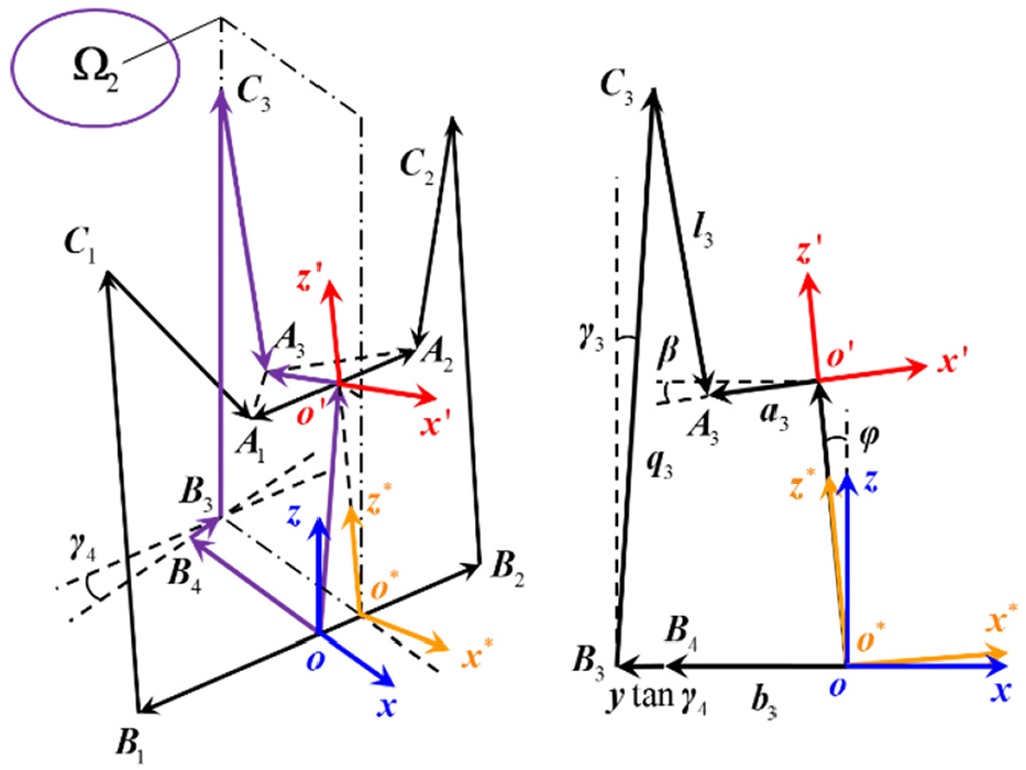
Kinematics vector diagram in
Then, perturb equation (14) with tiny errors, ignore the high-order infinitesimal terms, and achieve
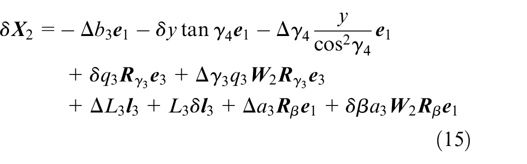
It is known that
Substitute equation (16) into equation (15), merge the similar terms, and yield
Subsequently, multiply both sides of equation (17) with
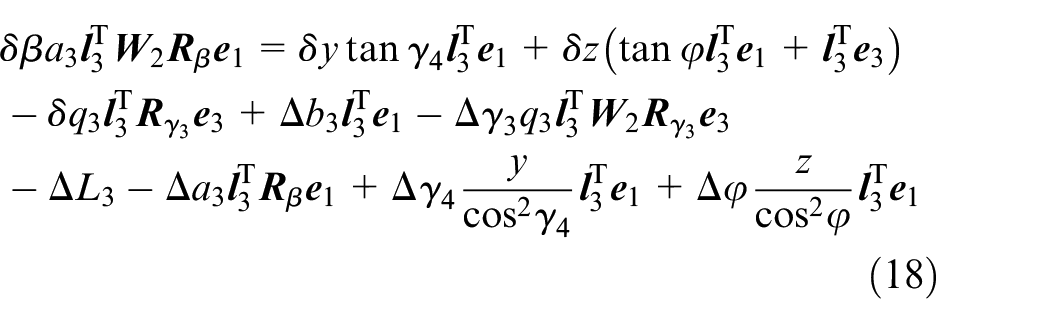
After that, divide both sides of equation (18) by the coefficient of
where

Modeling in
Isolate

Kinematics vector diagram in
Then, differentiate both sides of equation (20), and the error propagation formula developed in

Modeling of the RASPM
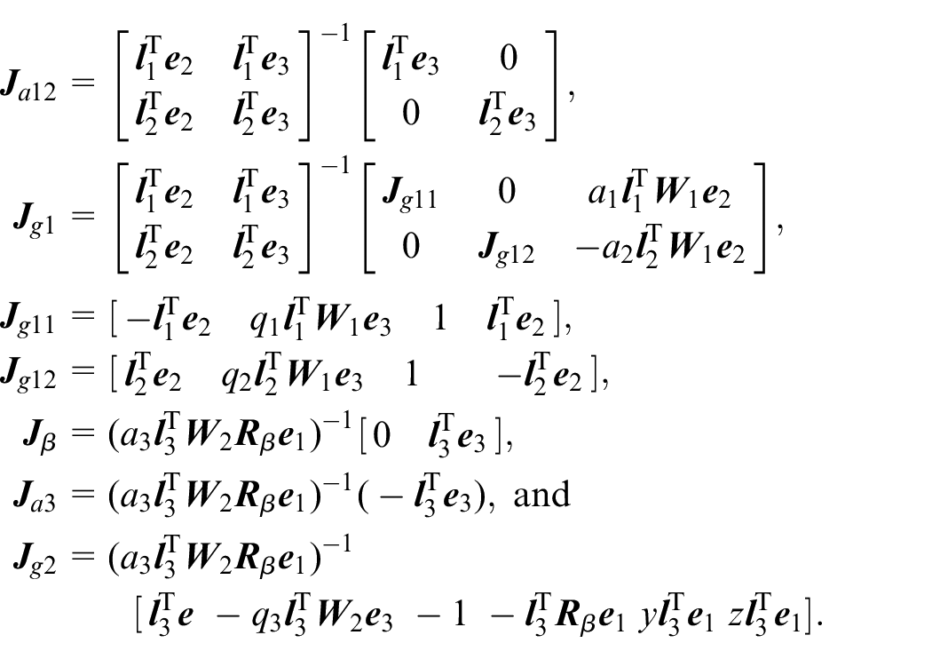
The nominal dimension parameters of the RASPM are listed in Table 2. Substitute the zero parameters into equations (4), (12), (19), and (21), and achieve

where
The nominal dimension parameters of the RASPM.
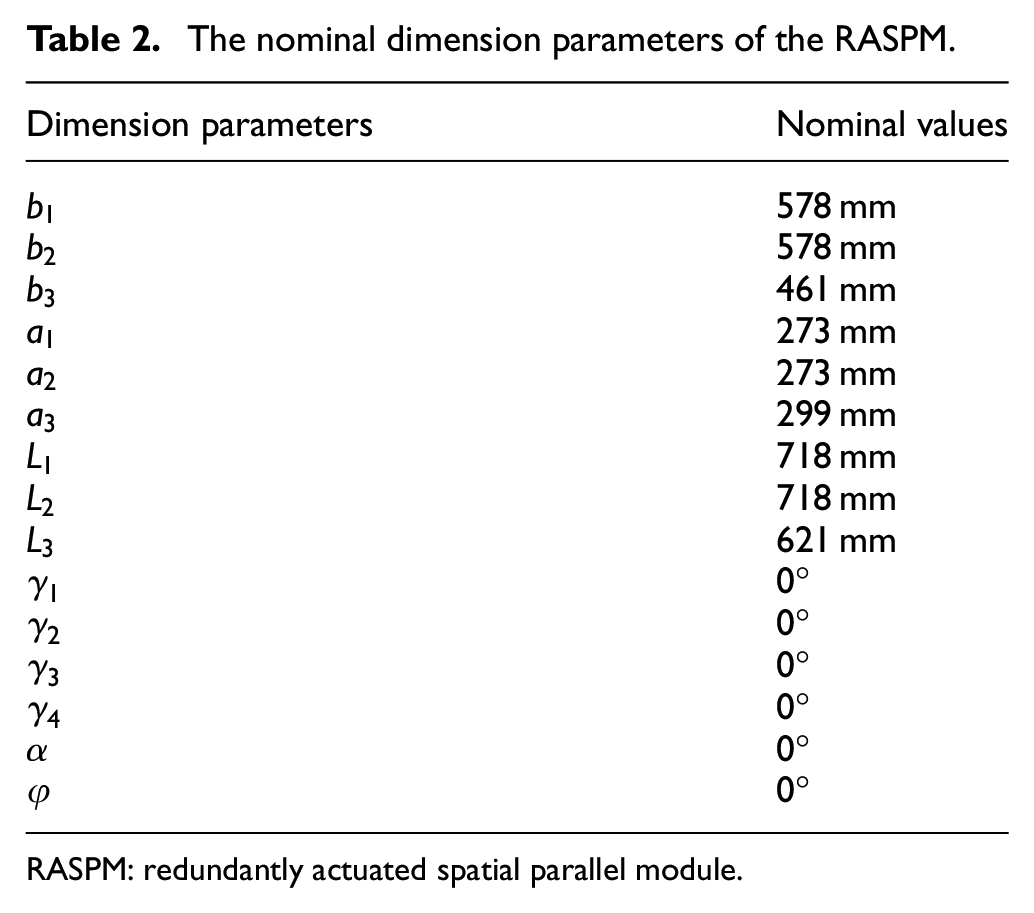
RASPM: redundantly actuated spatial parallel module.
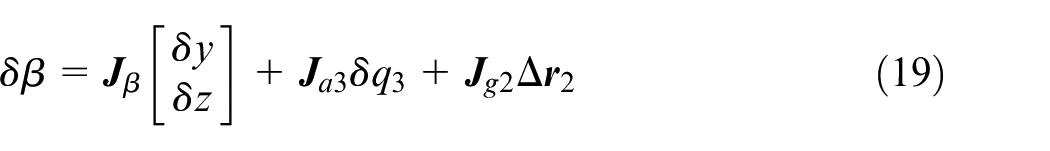
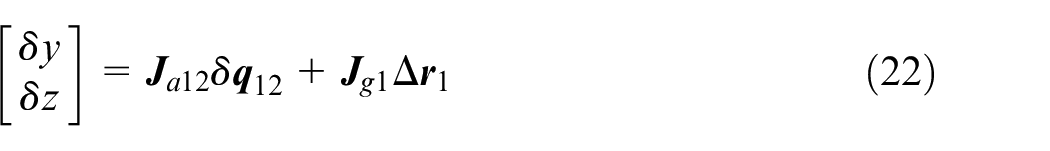
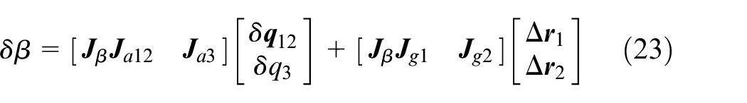
Then, unite equations (22) and (23), and the geometric error model of the RASPM can be expressed as

where
Proposed calibration method
Projection technique
Dealing with

Then, unite with

where
Because the torsional deformations are proportional to the distributed torques at AJs,

On this basis, substitute equation (27) into equation (28), then unite equation (25), and obtain
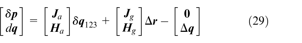
As observed in equation (29), the left side is the errors to be measured, while the right side should be the parameters to be identified, so the term associated with
Define the coefficient of
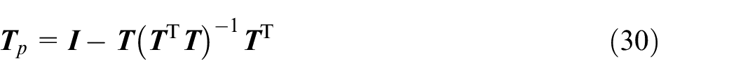
Therefore, multiply both sides of equation (29) with
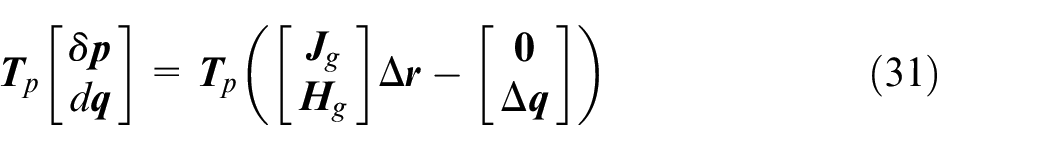
Without inaccessible error parameters
Error model reduction
From equation (31), it can be known that the following errors of AJs are still required. The general way is using additional sensors or gratings mounted on the AJs to measure the actual movements directly. 34 Nevertheless, it would raise up not only the investment for devices, but also the difficulties of designing and maintaining this machine tool system. Especially, if the machine tool has been assembled, it could not be realized sometimes.
In this article, an alternative treatment without additional sensors or gratings is proposed for RASPMs driven by joints with fixed moving axes to guarantee the operability and efficiency. First, choose an internal fixed pose as the reference for the calibrating zero position of the machine tool, such as the configuration determined by the center and surface of the rotary table. Then, with the help of external measuring instruments, the end-effector can align the calibrating zero position via adjusting each single AJ little-by-little. After that,
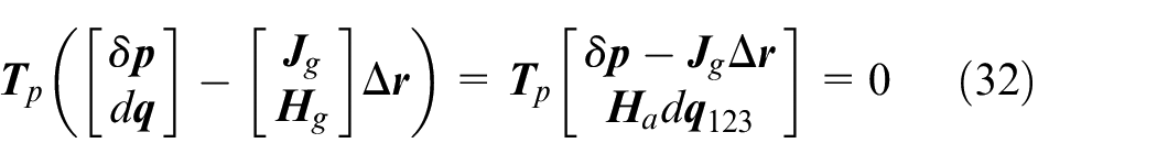
Second, handle

where
Finally, equation (33) is the practical error model of the RASPM developed by the above model reduction method.
Relative measurement and step identification
Because of lacking high-precision multidimensional measuring instruments to detect spatial pose errors of the end-effector, relative measurement (RM) and step identification (SI) 12 are adopted to calibrate the RASPM. Consequently, only low-cost measuring instruments are needed, although more operator intervention is required.
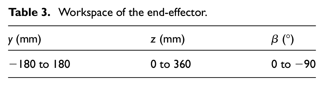
Since the rotation mobility of the RASPM is decoupled with its planar translation mobility, the moving ranges of each mobility are listed in Table 3. Accordingly, three forms of RM and SI are designed for the calibration work as follows.
Workspace of the end-effector.
RM1 and SI1: fix the nominal value of
where
RM2 and SI2: fix the nominal value of

where
RM3 and SI3: fix the nominal value of
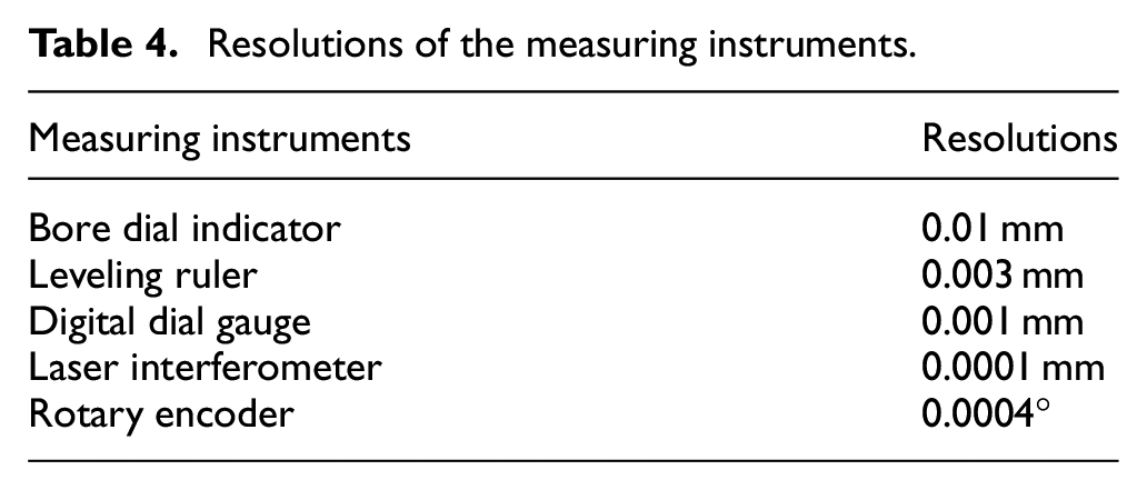
Based on the RMs, the combination of selected measuring instruments is listed in Table 4. Table 5 presents the details of RMs and the performances of SIs, which are estimated by the anti-disturbance indexes of the identifiable error parameters.12,35
Resolutions of the measuring instruments.
Details of RMs and performances of SIs.
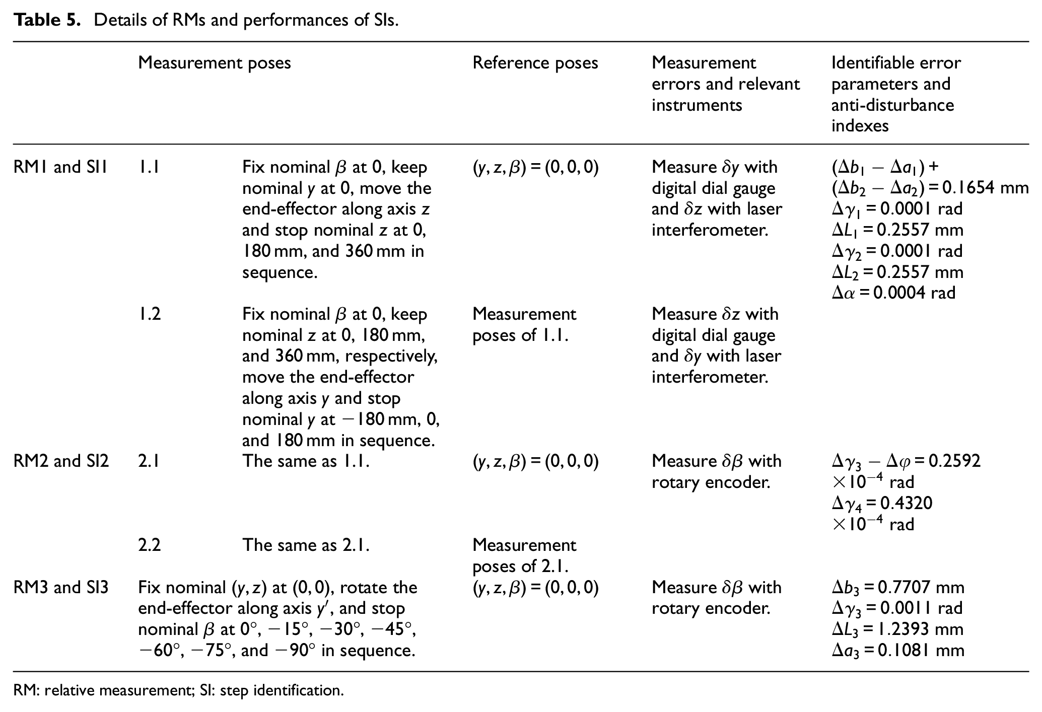
RM: relative measurement; SI: step identification.
Bilinear interpolation compensation
Note that after RM1 and SI1, only if the residual position errors
The schematic diagram is shown in Figure 6. Initially, mesh the moving ranges of the planar translation mobility into grids, and measure the relative coordinates of all the grid points with respect to the calibrating zero position at ready. Take the error compensation at

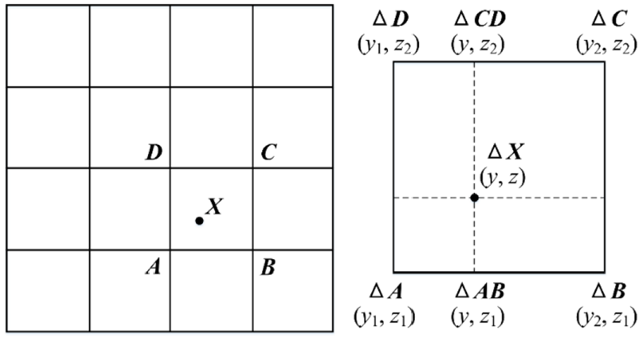
Schematic diagram of the BIC.
Similarly, the position error at
Then, linearly interpolate again between
In the end, revise the planar coordinate of
Kinematic calibration experiment
Executing procedures
Adjust AJs to align the axis of the spindle collinear with that of the rotary table using the bore dial indicator, and to align the surface of the moving platform parallel with that of the rotary table using the digital dial gauge at the same time.
Measure the following errors of the independent prismatic AJs with the laser interferometer, and eliminate them via the function of pitch compensation. Afterwards, conduct RM1 and SI1, update
Mesh the translational workspace into 5 × 5 grid, measure the residual position error at each grid point, and write them into the NC system as the BIC data.
Conduct RM2 and SI2, update
Conduct RM3 and SI3, update
Experimental results
According to the executing procedures, the kinematic calibration of the RASPM is conducted. The on-site pictures are exhibited in Figure 7, and the identified dimension parameters are listed in Table 6.
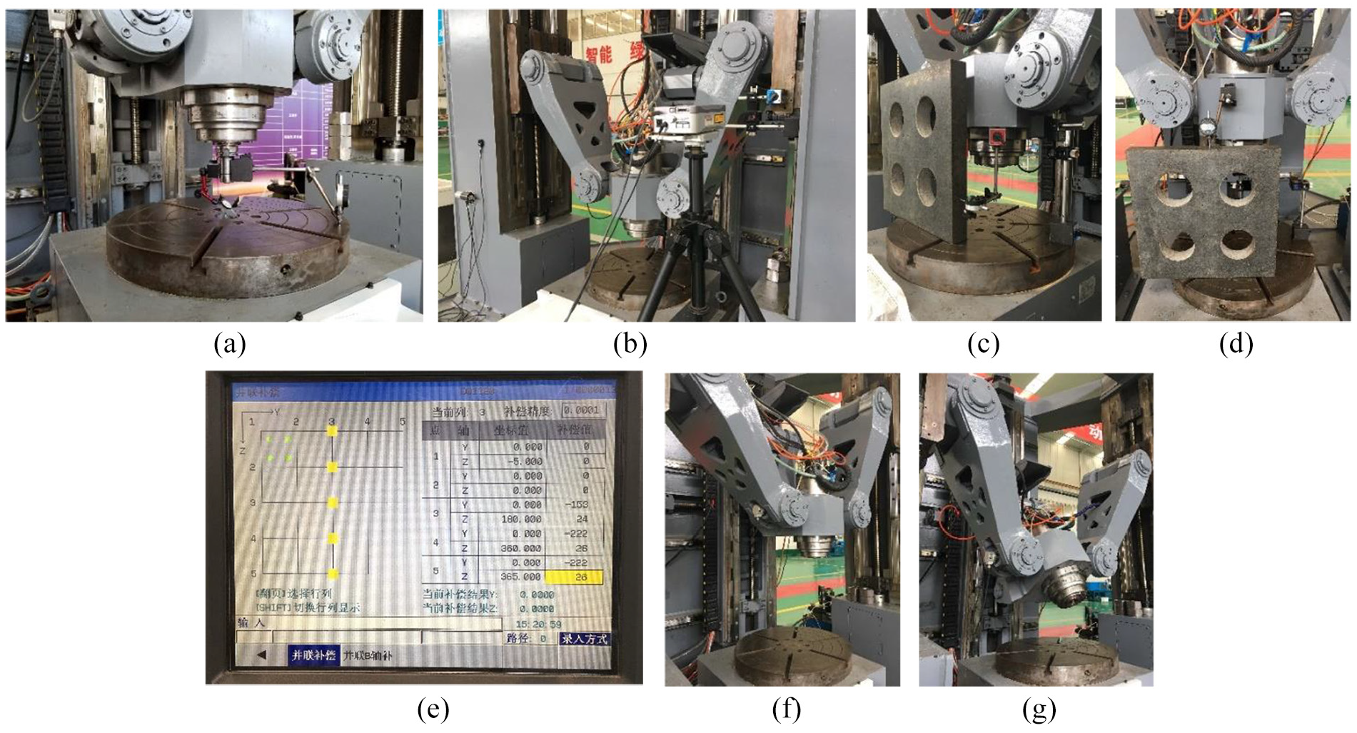
On-site pictures of the kinematic calibration experiment: (a) alignment with the calibrating zero position; (b) measurement for AJs’ pitch compensation; (c) RM1.1; (d) RM1.2; (e) interface of the BIC function; (f) RM2; and (g) RM3.
The identified dimension parameters of the RASPM.
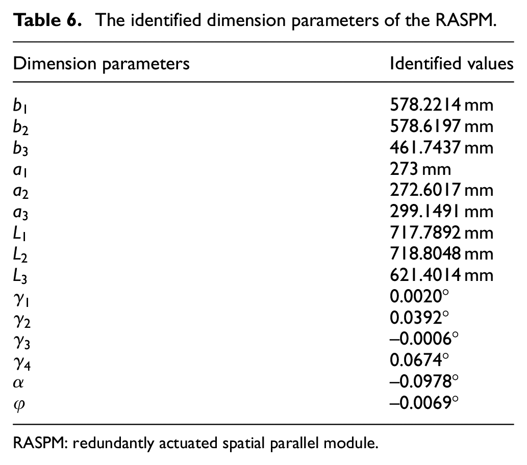
RASPM: redundantly actuated spatial parallel module.
Figures 8–11 present the experimental results of each executing procedure. As shown in Figure 8, the error peaks of
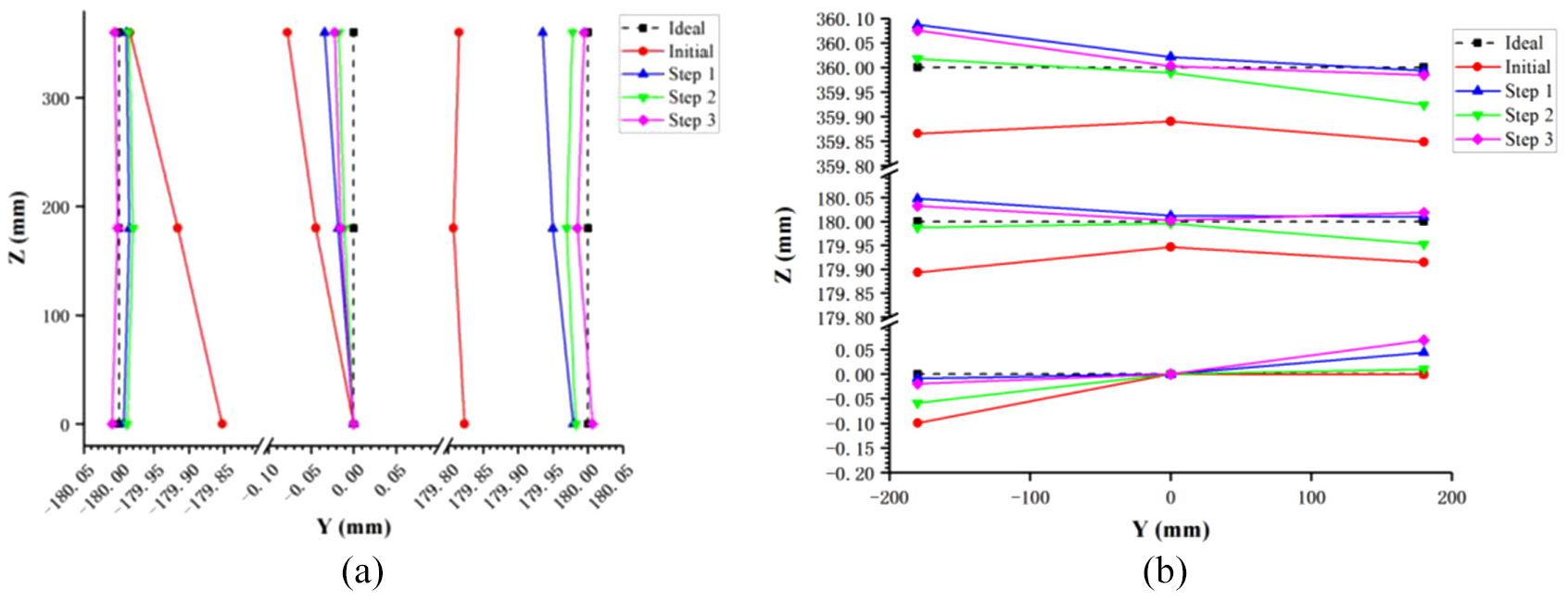
Position errors before and after RM1 and SI1: (a)
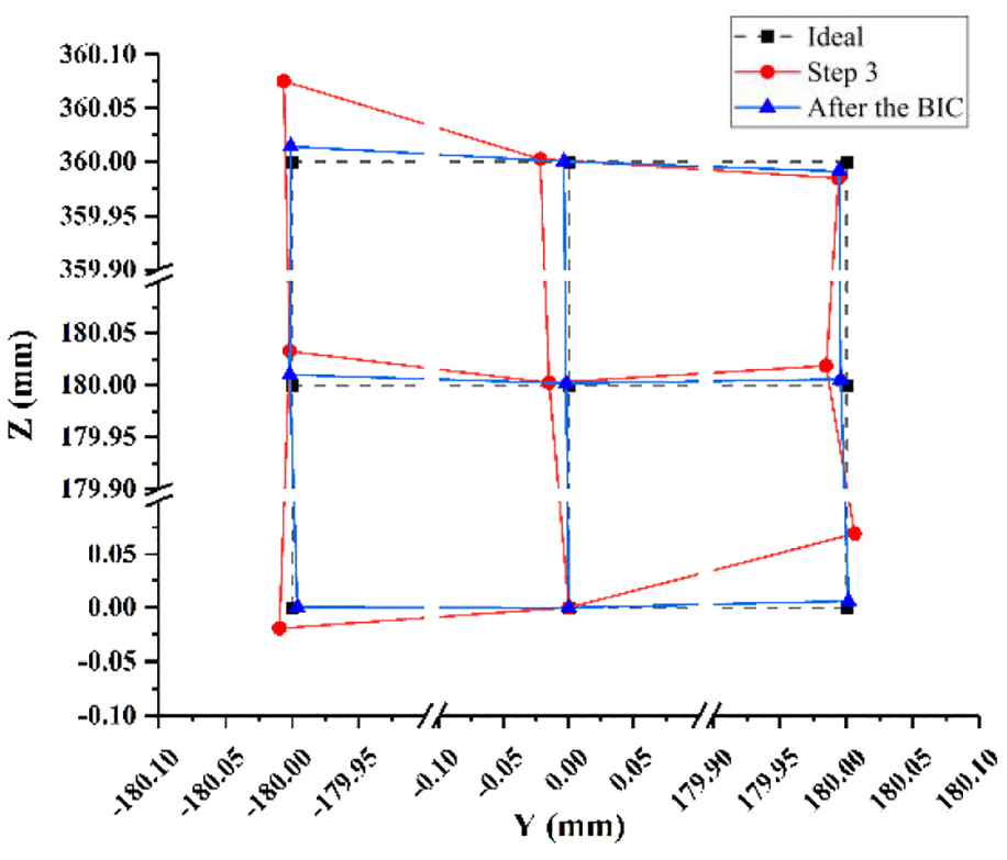
Position errors before and after the BIC.
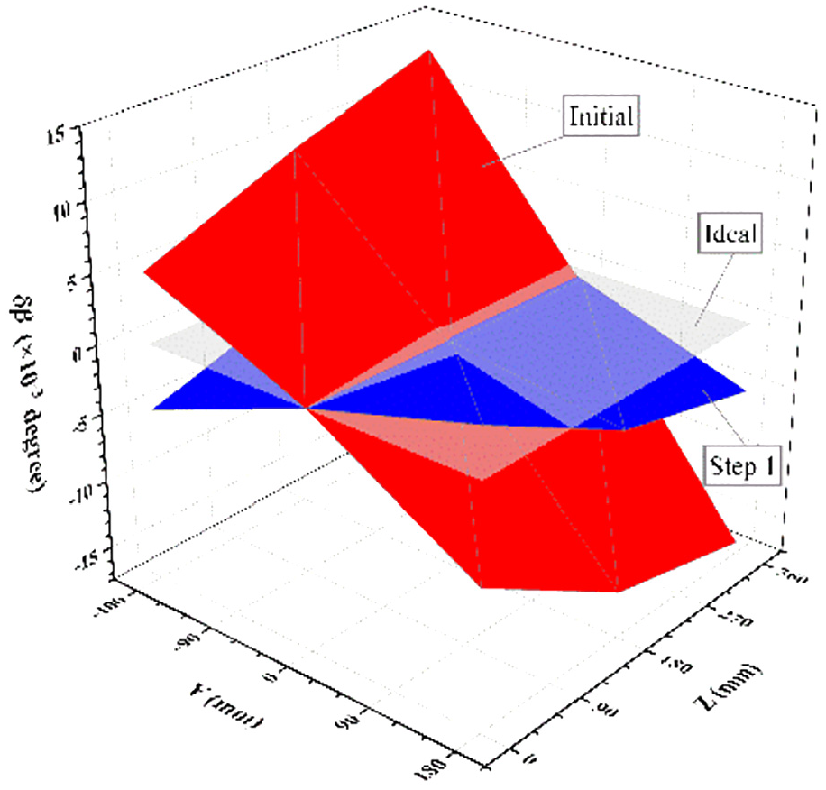
Orientation errors
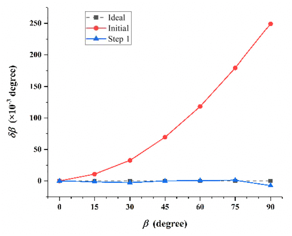
Orientation errors
Comparison with the previous method
Another experiment is carried out on the RASPM with the previous method for the CNRPM,
15
which keeps
After three steps of RM1 and SI1 as observed in Figure 12(a), the error peak of position components and the error range of measuring lines are convergent to 0.076 and 0.098 mm, respectively, with the previous method, while 0.075 and 0.096 mm, respectively, with the proposed method. Actually, the proposed method has almost reaches the convergence at Step 2, while the previous method gets slightly worsen at Step 4.
After three steps of RM3 and SI3 as observed in Figure 12(b), the error peak of orientation component is convergent to 0.012° with the previous method, while 0.007° with the propose method after only one step.
In summary, the proposed method is verified to be more efficient than the previous method for kinematic calibration of the RASPM. If investigate into why the residual errors of two experiments stay in a similar level, in our view, it is because the restrained deformations caused by force redundancy is getting smaller and smaller when geometric parameters are approaching their real values as experiments proceed. Still and all, almost half of the measurement time are saved comparing with the previous method, which means that the experiment duration can be reduced from 3 days at least into 2 days at most, and less operational errors will be brought in. For this sake, the proposed method is of great practical significance as well.
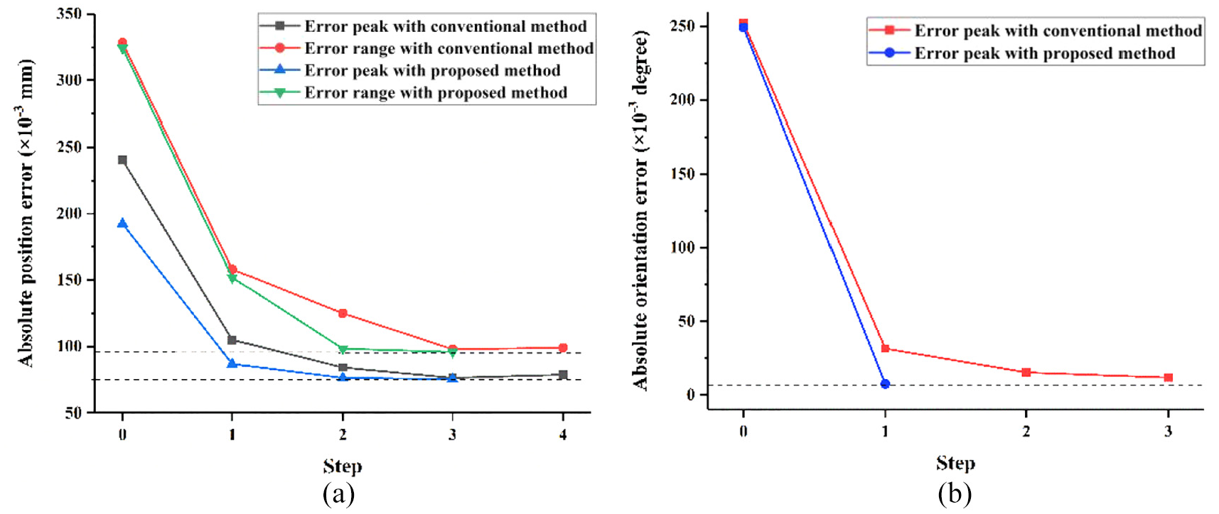
Comparisons between the results with the previous method and the proposed method: (a) absolute position errors and (b) absolute orientation errors.
Conclusion
This article proposes an improved method for kinematic calibration of the 3-DoF RASPM of a five-axis hybrid machine, and the following conclusions can be drawn from this study:
Three kinds of error models are developed for kinematic calibration of the RASPM sequentially. The geometric error model is established to involve the restrained deformations at AJs caused by the force redundancy, the applicable error model is established with projection technique to avoid AJs’ stiffness measurement or modeling, and the practical error model is established based on model reduction method to avoid additional sensors or gratings.
RM, SI, and BIC are adopted for kinematic calibration of the RASPM. On this basis, the concrete executing procedures are designed.
The kinematic calibration experiment is conducted on the RASPM. The results show that the max position and orientation errors are reduced from original −0.192 mm and 0.249° to 0.014 mm and −0.007°, respectively, which verifies the effectiveness of the proposed method.
The contrasting experiment is also conducted with the previous method for the CNRPM. The results show that much more steps are needed than the first experiment, which demonstrates the efficiency of the proposed method.
Footnotes
Declaration of conflicting interests
The author(s) declared no potential conflicts of interest with respect to the research, authorship, and/or publication of this article.
Funding
The author(s) disclosed receipt of the following financial support for the research, authorship, and/or publication of this article: This work was supported by the National Natural Science Foundation of China (grant numbers: 91748205 and 51675290).