
Abstract
Most of the existing energy-consumption models of machine tools are related to specific machine components and hence cannot be applied to other machine tools with different specifications. In order to help operators optimize machining parameters for improving energy efficiency, the tool tip cutting specific energy prediction model based on machining parameters and tool wear in milling is developed, which is independent of the standby power of machine tools and the spindle no-load power. Then, the prediction accuracy of the proposed model is verified with dry milling AISI 1045 steel experiments. Finally, the influence of machining parameters and tool wear on tool tip cutting specific energy is studied. The developed model is independent of machine components, so it can reveal the influence of machining parameters and tool wear on tool tip cutting specific energy. The tool tip cutting specific energy reduces with the increase in the cutting depth, side cutting depth, feed rate, and cutting speed, while increases linearly as the tool wears gradually. The research results are helpful to formulate efficient and energy-saving processing schemes on various milling machines.
Introduction
Manufacturing converts raw materials into products using electrical energy, while simultaneously generating emissions. Manufacturing accounts for about 30%–50% of the total global energy consumption. Energy saving and emission reduction are urgently vital tasks of the manufacturing industry. Cleaner production and green manufacturing have become the developmental trend of machining industry. 1
Computer numerical control (CNC) machine tools are equipment widely used in machining industry. Many researchers have studied the measures to promote energy saving and emission reduction in CNC machine tools: (1) to measure the idle power of the old and long-serving machine tools and improve inefficient machine tools; (2) to optimize the numerical control (NC) program to keep the tool path as continuous as possible and reduce the sudden change in motion direction and motion speed, so as to reduce the energy consumption of driving motor; (3) to adopt auxiliary devices such as hydraulic, pneumatic, lubricating, and cooling with high efficiency; (4) to reduce non-cutting process and shut down the power supply of auxiliary devices which are not used in time; and (5) to adopt the micro-lubrication technology for cutting fluid in the machining process.2–4
In addition, reasonable machining parameters are helpful to achieve energy-saving manufacturing. Consequently, the efficient energy-consumption prediction model of machine tools is of great significance for optimizing machining parameters and reducing energy consumption. The energy consumption can be predicted according to specific energy consumption, intelligent algorithm, processing stages, and machine components.5–7
The specific energy consumption is the energy consumption to remove unit volume material, which reflects the relationship between the energy consumption and material removal volume. Li and Kara 8 developed a prediction model of specific energy consumption based on power measurements on turning machine to consider both dry and flood cooling conditions with prediction accuracy of more than 90%. Li et al. 9 put forward an improved prediction model of specific energy consumption as a function of material removal rate (MRR) and spindle speed. Zeng et al. 10 proposed a general empirical specific energy-consumption model for milling machine at certain power level, with an average absolute residual ratio of 6% and specific energy-consumption prediction accuracy of 91.5%.
Many researchers adopted intelligent algorithm to predict energy consumption of machine tools in cutting. Zhao et al. 11 developed a specific energy-consumption prediction model in turning, adopting the single hidden layer feedforward back propagation (BP) neural network, with the cutting speed, feed rate, and depth of cut as input. Zhou et al. 12 established an energy-consumption prediction model of plane grinder processing system based on BP neural network, with the wheel speed, feed speed of worktable, and grinding depth as input, which can predict the energy consumption of the grinder well. Zhang et al. 13 developed an energy-consumption prediction model for milling process from multi-stage perspective with improved gene expression programming algorithm.
The energy consumption of machine tools can be obtained based on different processing stages. Mori et al. 14 developed a model considering the energy consumption in cutting state and non-cutting state, including the positioning and spindle acceleration, material removal, and returning the spindle to the tool exchange position after machining. Furthermore, machining processes can be decomposed into two parts: steady state and transient state. Transient state is the transition process between two steady states, which may lead to the peak power. So, Jia et al. 15 introduced an energy-consumption modeling method for machining transient state based on finite state machine theory. Zhou et al. 16 presented energy-consumption step (ECS) to describe various types of energy-consumption procedures in workpiece machining uniformly and developed an energy-consumption model for the whole machining process of a workpiece including machining ECS, transportation ECS, storage ECS, and various sub-ECS.
The energy consumption of machine tools can be obtained based on machine components under given cutting conditions. He et al. 17 developed a method to estimate the energy consumption in machining which can be used to optimize NC codes to improve energy efficiency. Xu et al. 18 divided the energy consumption of machine tools into four sections: no-load energy consumption of the spindle drive system, no-load energy consumption of the feed drive system, energy consumption of the auxiliary systems, and energy consumption of the machining process including tool tip cutting energy consumption and additional energy losses. Lee et al. 19 presented a simulation-based framework for estimating the energy consumption of machine tool at the component level, including feed drive system and spindle drive system. Jiang et al. 20 classified the energy sources of CNC continuous generating grinding machine tool into gear grinding system, grinding wheel dressing system, and auxiliary system, and the proposed energy-consumption model can support for energy consumption forecasting and energy-saving optimization.
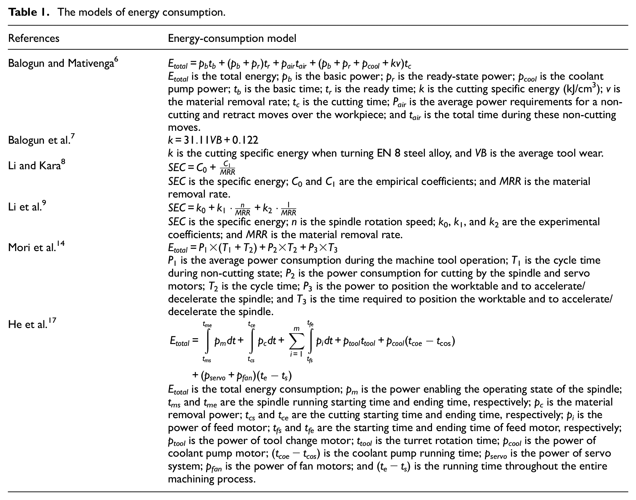
Some typical energy-consumption models in the above literatures are listed in Table 1.
The models of energy consumption.
In sum, the researchers have done in-depth research on the energy-consumption models of machine tools and the optimization methods of machining parameters. Various energy-consumption prediction models of machine tools have been established. But most of them are related to specific machine components and hence cannot be applied to other machine tools with different specifications.
The objectives of this article are threefold: (1) to develop a tool tip cutting specific energy prediction model in milling based on machining parameters and tool wear, which is independent of the standby power of machine tools and the spindle no-load power; (2) to verify the introduced model with dry milling experiments of AISI 1045 steel; and (3) to reveal the influence of machining parameters and tool wear on tool tip cutting specific energy.
Power and energy-consumption characteristics of machine tools in milling
CNC milling machines are generally used to process plane contour parts, variable angle parts, and three-dimensional (3D) surface parts. Milling process consumes electrical energy and converts raw materials into products with desired shape and characteristics, as shown in Figure 1.

Energy conversion in milling process.
CNC milling machines have many functional components, mainly including spindle system, feed-axis system, cooling system, lubrication system, machine control unit (MCU), as well as auxiliary systems such as lighting device, fan, chip removal system, and tool changer. After machine start-up, the power consumed by CNC milling machine when the lubrication system, MCU, lighting device, and fan are working only is called standby power Pidle which is a constant. When the spindle rotates without load, the power consumed by the spindle motor is called spindle no-load power Psno. The cooling system power Pcool is the power of coolant pump motor when coolant is used in milling.
The complete milling machine working process includes start-up, standby, spindle start, no-load operation, cutting stage, no-load operation, spindle stop, standby, and shutdown shown in Figure 2. In the cutting stage, the power of milling machine Pcutting includes standby power Pidle, spindle no-load power Psno, tool tip cutting power Ptooltip, cooling system power Pcool, feed-axis no-load power, and chip removal power. Compared with the spindle no-load power, the feed-axis no-load power and chip removal power during milling are very small and often negligible. 2 Then, the machine tool power in cutting stage is

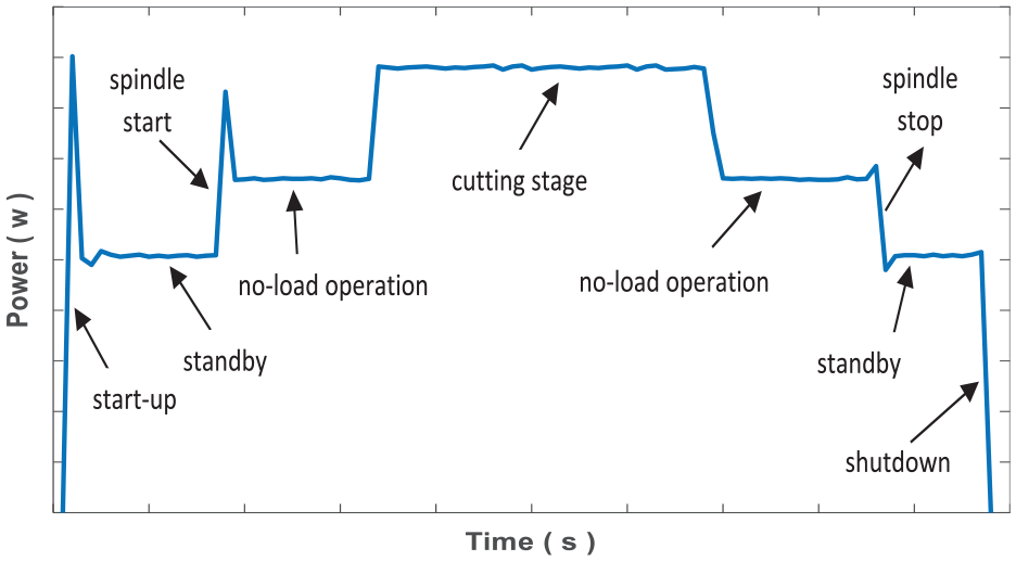
The complete CNC milling process.
The energy consumption of CNC milling machine in cutting stage Ecutting mainly includes standby energy consumption Eidle, spindle no-load energy consumption Esno, tool tip cutting energy consumption Etooltip, and cooling system energy consumption Ecool

where Eidle mainly includes the energy consumption of lubrication system, MCU, lighting device, and fan, which depends on the working time of machine tool from start-up to shutdown; Esno is related to the spindle system structure and the spindle motor power characteristics, which depends on the spindle speed and motion time; Ecool depends on the power of coolant pump motor; and Etooltip refers to the pure material removal energy consumption which governs chip formation and surface generation, relevant to process conditions and workpiece material.
Tool tip cutting specific energy prediction model in milling
Tool tip cutting specific energy
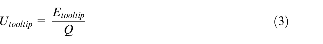
In cutting stage, the tool tip cutting specific energy Utooltip is defined as the tool tip cutting energy consumption to remove unit volume material 21
Diaz et al. 21 developed an empirical model to predict Utooltip

where ae is the side cutting depth in millimeter, ap is the cutting depth in millimeter, z is the number of teeth on the cutting tool, vf is the feed rate in millimeter/minute, n is the spindle speed in revolutions/minute, and k and b are the empirical constants.
Tool tip cutting specific energy Utooltip was assumed to be a constant in some models. For instance, Aramcharoen and Mativenga 22 calculated the tool tip cutting energy consumption Etooltip in the T316L stainless steel cutting with equation (5)

where MRR is the material remove rate in cubic centimeter/minute and tcutting is the cutting time in minutes.
Tool tip cutting specific energy prediction model based on machining parameters and tool wear
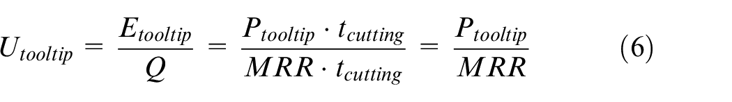
Above all, a method for measuring and calculating tool tip cutting specific energy with power analyzer in milling is established in the article. Convert the tool tip cutting specific energy Utooltip into a function related to tool tip cutting power Ptooltip and MRR according to equation (3)
The tool tip cutting power Ptooltip can be measured according to equation (7)

Substituting equation (7) into equation (6), Utooltip can be obtained
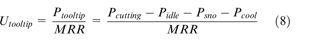
So, the tool tip cutting specific energy can be measured and calculated in milling according to equation (8). The inconvenience of this method is that Utooltip can only be measured and calculated by power analyzer in milling and cannot be calculated before processing. Establishing a simple and efficient tool tip cutting specific energy prediction model, which can predict and calculate Utooltip before processing, is of great significance for optimizing and selecting machining parameters to achieve energy-saving manufacturing.
In theory, tool tip cutting specific energy is closely related to cutting force and machining parameters. Cutting force is exponentially related to machining parameters, so the tool tip cutting specific energy model based on machining parameters is established by Zhang et al. 23

where ap is the cutting depth in millimeter, ae is the side cutting depth in millimeter, f is the feed rate in millimeter/revolution, v is the cutting speed in meter/minute, and b, c, d, x, and y are the undetermined coefficients.
However, the machining experiments with the same workpiece material and machining parameters show that Utooltip is different as the tool wears gradually. Tool wear is inevitable in the cutting process. 24 The fresh machined surface contacts with the tool flank and rubs against each other in cutting, which causes the wear of tool flank. 25 As shown in Figure 3, tool wear process can be divided into three stages, including initial wear stage, normal wear stage, and sharp wear stage. Generally, the wear rate is fast in initial wear stage. The normal wear stage is relatively slow and uniform, and the wear amount increases approximately in proportion with the cutting time. In the sharp wear stage, the cutting force and temperature increase rapidly, so this stage should be avoided in order to ensure the processing quality in milling.
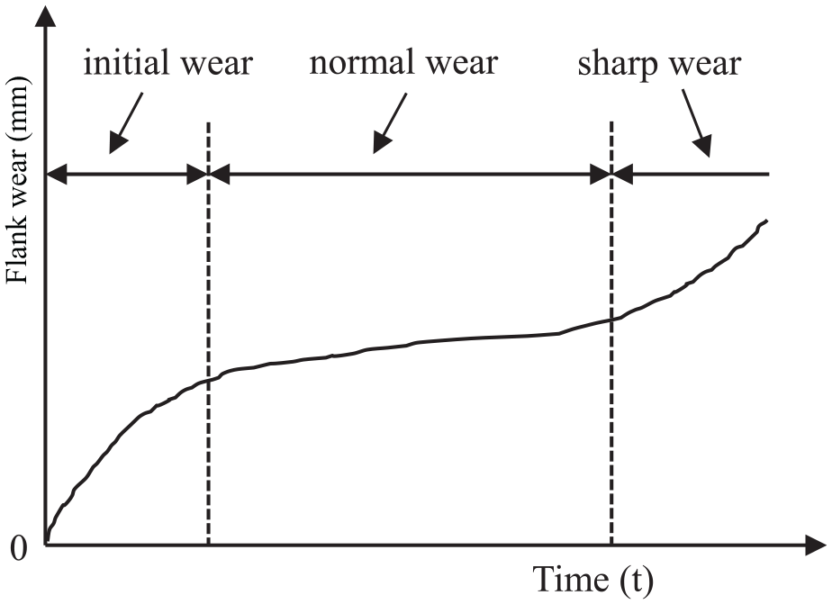
Tool wear process in milling.
In short, the Utooltip is relative to both machining parameters and tool condition. Assuming that tool tip cutting energy is 25% of the total energy demand, tool flank wear can increase the total energy consumption by an average of 13%. 26 Tool flank wear is zero for a sharp tool, and the tool cannot be used again when tool wear reaches 0.3 mm generally. Let VB be the tool flank wear in millimeter. Regression analysis results of milling experiments show that Utooltip has an exponential relationship with (1 + VB). 4 In this article, an exponential regression model is developed to predict Utooltip with machining parameters (ap, ae, f, and v) and tool flank wear (VB) on the basis of equation (9)
where b, c, d, x, y, and z are the undetermined coefficients. Then, the tool tip cutting energy consumption in milling can be obtained according to material volume removed in milling.
Experimental verification
Milling experiments and power measurement
Dry milling AISI 1045 steel and power measurement are performed, as shown in Figure 4. The CNC equipment is XD-40A vertical milling machine with FANUC-0i CNC system. The spindle system is driven by servo motor with rated torque of 38.5 N·m, and the spindle bearings are lubricated with grease.
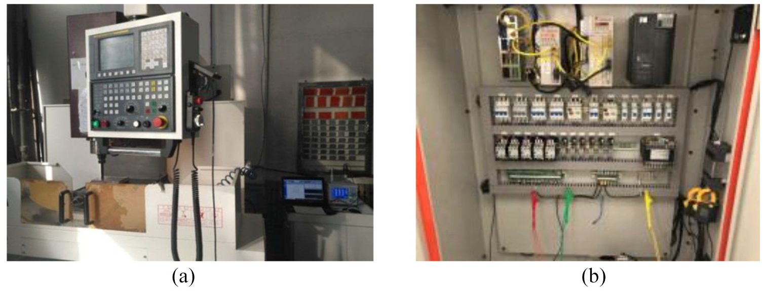
The AISI 1045 steel milling and power measurement: (a) milling and testing and (b) electrical cabinet wiring.
The power analyzer WT1800 and shunts are adopted to measure various power and energy signals in milling. The voltage and current signals of machine tool are connected to WT1800, and the power and energy signals are read with WTViewerEfree software. The standby power and spindle no-load power of the machine tool are measured before processing. After machine start-up, the standby power Pidle is 588 W when the lubrication system, MCU, lighting device, and fan are working only. The spindle no-load power, Psno, increases approximately linearly with the increase in the spindle speed n, as shown in Figure 5.
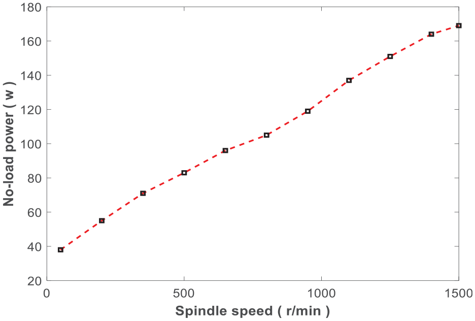
The characteristics of spindle no-load power.
The dimensions of experimental workpieces are 200 mm (length) × 150 mm (width) × 60 mm (height). The tool is a 20-mm-diameter rotatable-position end mill cutter (TAP300R-2020-160) with two KYOCERA cemented carbide inserts (APMT1135PDER-KZ-A). The workpiece surface is face milled prior to cutting in order to remove surface defects such as spots, pits, scratches, and inhomogeneity.
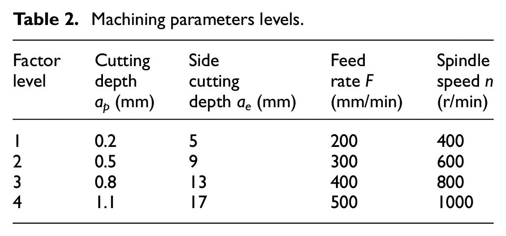
The orthogonal experiments with 16 groups of four factors and four levels are designed with Taguchi method to mill the upper surface of workpiece. The processing parameter include cutting depth ap in millimeter, side cutting depth ae in millimeter, feed rate F in millimeter/minute, and spindle speed n in revolutions/minute. The processing parameter levels in the experiments are shown in Table 2.
Machining parameters levels.
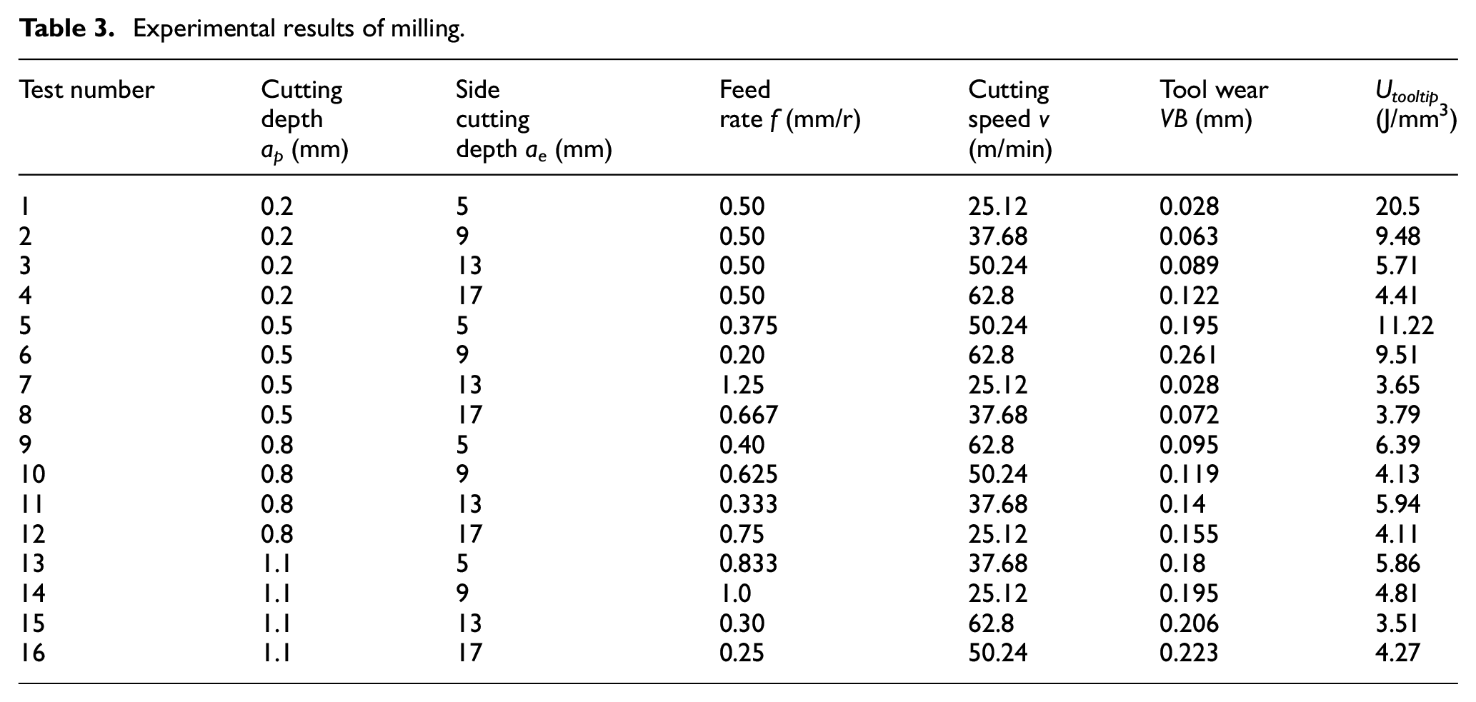
In each milling experiment, the cutting power Pcutting with power analyzer is measured, and the true value of tool tip cutting specific energy Utooltip is obtained by equation (8). The tool flank wear is measured twice before and after milling, and the average value is taken as the tool wear VB in this milling experiment. Converting feed rate F in millimeter/minute to f in millimeter/revolution with equation (11) and spindle speed n in revolution/minute to cutting speed v in meter/minute with equation (12)

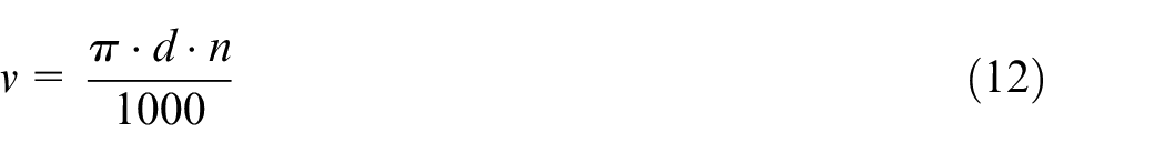
where d is the tool diameter. Then, the machining parameters, tool wear, and tool tip cutting specific energy in milling experiments are obtained, as shown in Table 3.
Experimental results of milling.
Verification of the developed tool tip cutting specific energy prediction model
Comparison of prediction models
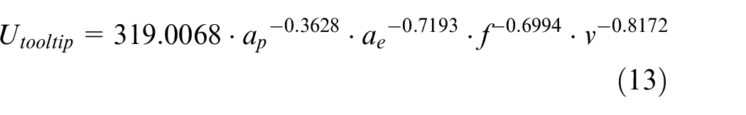
First, substituting 16 sets of data in Table 3 into equation (9), the undetermined coefficients in the regression model are calculated based on least square method: b = 319.0068, c =−0.3628, d=−0.7193, x = −0.6994, and y = −0.8172. The correlation coefficient R2 of the regression model is 0.98, and the mean square error (MSE) is 0.1470. Then, the tool tip cutting specific energy prediction model in AISI 1045 steel milling based on milling parameters is obtained
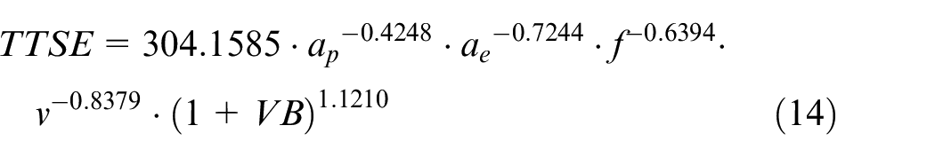
Second, substituting 16 sets of data in Table 3 into equation (10), the undetermined coefficients in the regression model are calculated based on least square method: b = 304.1585, c = −0.4248, d = −0.7244, x = −0.6394, y = −0.8379, and z = 1.1210. The correlation coefficient R2 of the regression model is 0.99, and the MSE is 0.0396. Then, the tool tip cutting specific energy prediction model in AISI 1045 steel milling based on machining parameters and tool wear is obtained
The prediction error comparison of tool tip cutting specific energy model shown in equations (13) and (14) is shown in Figure 6.
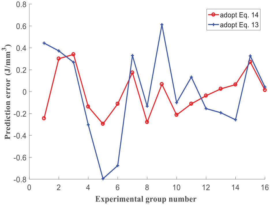
Prediction error comparison.
Experimental verification
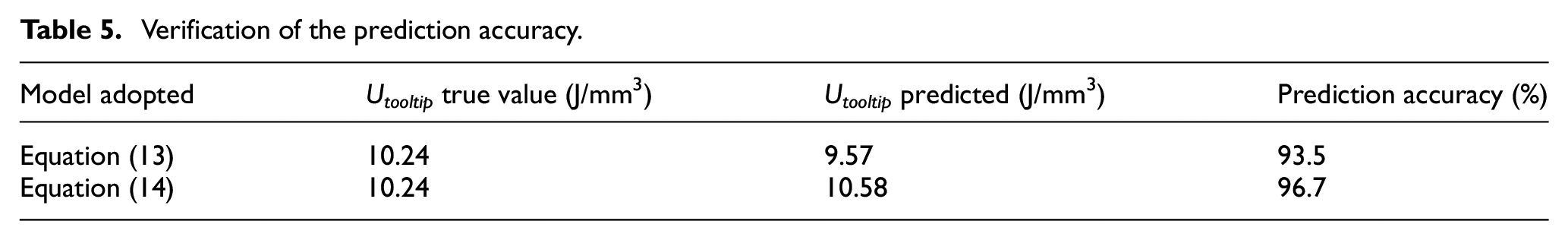
A new set of machining parameters shown in Table 4 is used to verify the prediction accuracy of the models. As shown in Table 5, the true value of Utooltip calculated with equation (8) using power analyzer is 10.24 J/mm3, the predicted value of Utooltip calculated with equation (13) is 9.57 J/mm3, with prediction accuracy of 93.5%; while the predicted value of Utooltip calculated with equation (14) is 10.58 J/mm3, with prediction accuracy of 96.7%.
The machining parameters in the verification experiment.

Verification of the prediction accuracy.
According to the tool tip cutting specific energy predicted and material volume removed in milling, the tool tip cutting energy consumption can be calculated. For example, in the verification experiment shown in Table 4, the material volume removed is 12,000 mm3, the Utooltip predicted with equation (14) is 10.58 J/mm3, then the tool tip cutting energy consumption predicted before processing is 126.96 kJ, while the true tool tip energy consumption in processing is 122.88 kJ.
The experimental results show that the prediction model shown in equation (14) has higher prediction accuracy than prediction model shown in equation (13). Therefore, the tool wear condition cannot be ignored in the tool tip cutting specific energy prediction.
Influence of machining parameters and tool wear on Utooltip
Machining parameters and tool wear have important impact on cutting force and cutting temperature. The influence of ap, ae, f, v, and VB on Utooltip in AISI 1045 steel milling is studied.
As shown in Figure 7(a)–(c), in general, the increase in ap, ae, and f leads to the increase in MRR, so the Utooltip decreases. With the increase in the cutting speed v, the cutting temperature rises and causes the reduction in strength and hardness of workpiece surface, so the cutting force cut down and Utooltip decreases as shown in Figure 7(d).
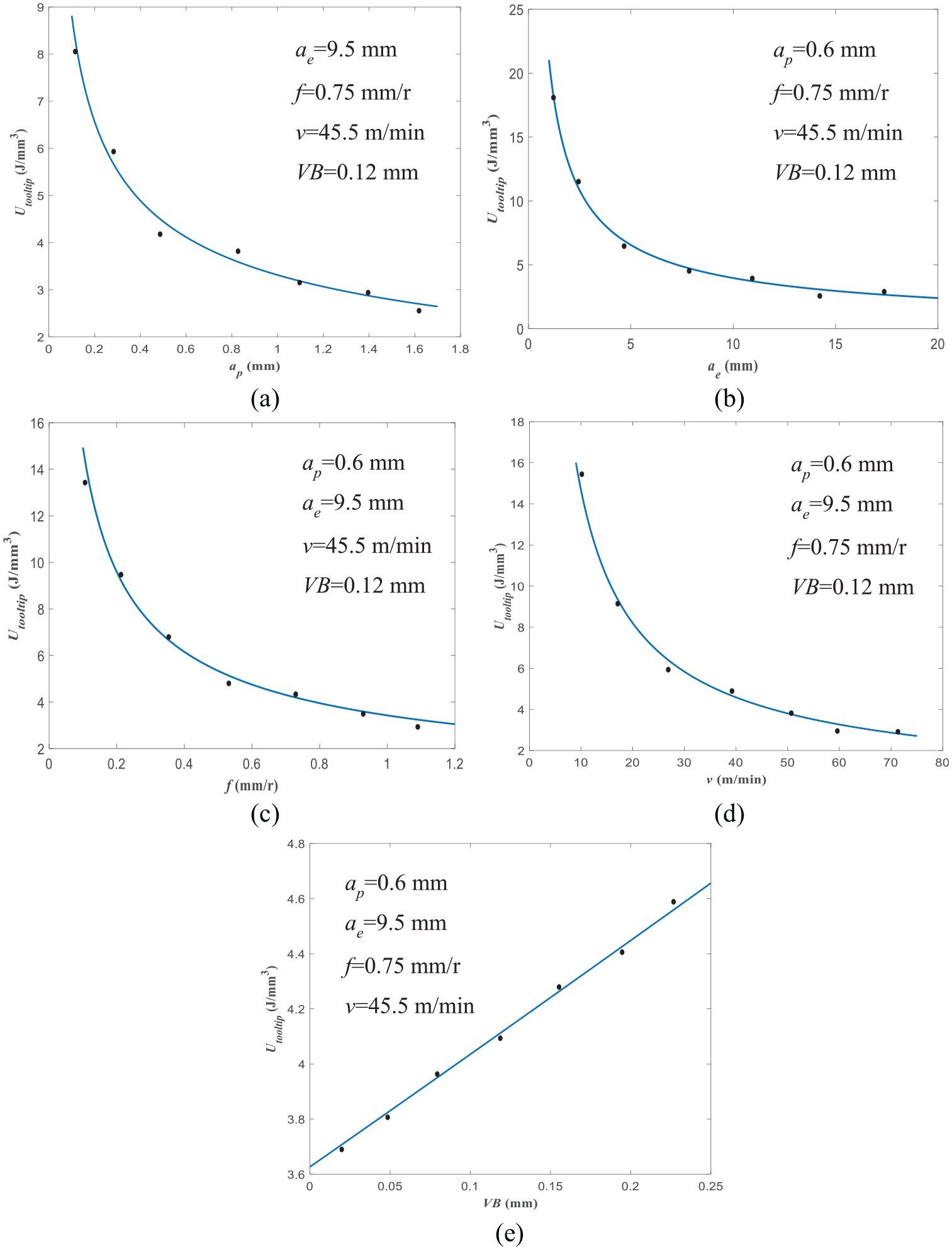
Influence of machining parameters and tool wear on Utooltip: (a) curve between Utooltip and ap, (b) curve between Utooltip and ae, (c) curve between Utooltip and f, (d) curve between Utooltip and v, and (e) curve between Utooltip and VB.
As shown in Figure 7(e), Utooltip increases linearly with the increase in the tool wear VB. The reason is that when the tool flank is worn out, a small edge with a back angle of 0 is formed on the tool flank. The larger the tool flank wear, the larger the area of the small edge. So, the contact area between tool flank and workpiece adds, and the cutting force and Utooltip increase.
Therefore, ap in the range of 0.6–1.6 mm, ae in the range of 5–12 mm, f in the range of 0.4–1 mm/r, v in the range of 25–75 m/min, and VB in the range of 0–0.2 mm are helpful to reduce tool tip cutting specific energy, ensure machining quality, and extend tool life in AISI 1045 steel milling.
Conclusion
In this article, the tool tip cutting specific energy prediction model based on machining parameters and tool wear is developed. The prediction model is verified in dry milling AISI 1045 steel, and the influence of machining parameters and tool wear on tool tip cutting specific energy is studied. The main conclusions are as follows:
The tool wear has important impact on cutting force and energy consumption of machine tool. The developed tool tip cutting specific energy prediction model based on machining parameters and tool wear is simple with high prediction accuracy and independent of the specific machine tool components, which is helpful to select energy-saving machining parameters on various milling machines.
Generally, the tool tip cutting specific energy reduces with the increase in the cutting depth, side cutting depth, and feed rate in milling.
The increase in the cutting speed causes the reduction in strength and hardness of workpiece surface, so the cutting force cut down and the tool tip cutting specific energy decrease in milling.
The tool tip cutting specific energy increases linearly as the tool flank wears gradually. The cutting tool should be kept in the initial wear and normal wear stage in milling.
Only the tool flank wear is considered in the tool tip cutting specific energy prediction in this article. In addition, the tool rake wear is serious during cutting. The influence of tool rake wear on cutting specific energy will be studied in future.
The multi-objective optimization of cutting specific energy, processing efficiency, and surface quality in hard-to-cut materials milling would be an interesting topic.
Footnotes
Declaration of conflicting interests
The author(s) declared no potential conflicts of interest with respect to the research, authorship, and/or publication of this article.
Funding
The author(s) disclosed receipt of the following financial support for the research, authorship, and/or publication of this article: This work was supported by the Project of Shandong Province Natural Science Foundation of China (No. ZR2016EEM29) and the Project of Shandong Province key research development of China (No. 2017GGX30114).