
Abstract
In the deep-hole boring process on pure niobium tube, there exist some problems including serious tool wear, tough chips, and poor surface quality. In order to bore high-quality deep holes on rolled niobium tube, the cutting tool structure and boring process parameters suitable for machining rolled niobium tube were designed and two experimental schemes were proposed. The results showed that the geometric parameters of the cutting tool and process parameters have important influences on the tool wear, chip morphologies, hole-axis deflection, and hole surface roughness. By adjusting the geometric parameters of the cutting tool and boring process parameters, reasonable geometric parameters of the cutting tool and boring process parameters were obtained.
Introduction
Niobium has been widely used in aerospace, petrochemical industry, and medical devices because of its characteristics of excellent corrosion resistance, high strength, good plasticity and ductility, and superconductivity. 1 However, the pure niobium tube is quite difficult to machine due to its poor machinability which is mainly manifested in high cutting temperature, large cutting force, severe work hardening, tough chips, and tool wear. 2 With the wide applications of pure niobium tube, the deep-hole machining techniques are applied to process the components. 3 Currently, these techniques mainly include the gun drilling, 4 twist drilling, 5 and boring. 6 Among these technologies, deep-hole boring has the advantages of flexibility, applicability, low cost, and automatic rectification of the hole axis.7,8 Therefore, deep-hole boring is widely used in deep-hole processing of difficult materials.
The main evaluation index used to assess the deep-hole boring is the hole surface quality. 9 The hole surface quality is affected by the machining conditions such as cutting tools, 10 workpiece material property, and process parameters. 11 The cutting tool is one of the critical components affecting hole surface quality. 9 Choosing appropriate geometric parameters of cutting tool could improve the tool wear, chip morphology, 12 and process reliability, so as to hole surface roughness. 13 The geometric parameters of the cutting tool include rake angle, relief angle, inclination angle, and cutting edge angle. To reduce the surface roughness, the appropriate relief angle is selected to avoid the friction action caused by the spring back of the inner hole with the rear face of the cutting tool. 14 With the increase of rake angle, the cutting force decreases and chip contour becomes smoother. 15 In addition to geometric parameters of the cutting tool, hole surface quality is also affected by the process parameters and workpiece material.16,17 Siddiquee et al. 9 optimized the process parameters (cutting fluid, speed, feed, and hole-depth) using the Taguchi method based on the evaluation of surface roughness and found that the cutting speed, cutting fluid, and feed rate make significant contributions to the machined surface quality. The process parameters, including cutting speed and feed rate, can be optimized to achieve minimum surface roughness.18,19 Cutting speed is identified as a significant parameter of influencing the tool wear. 20 The severe tool wear had a negative effect on the final hole surface quality and hole-axis deflection. 21
To guarantee the hole surface quality and the axial straightness of the machined hole, the deep-hole boring of pure niobium tube was investigated. Two kinds of experimental schemes of the boring process were designed. By analysing the tool wear, chip morphologies, hole surface roughness, and hole-axis deflection in each step, the geometric parameters of the cutting tool and process parameters in the subsequent steps were continuously adjusted, and reasonable cutting tool structure and process parameters were obtained.
Experimental procedures
The experiments were conducted on the deep-hole boring equipment shown in Figure 1. It includes lather, centre rest, boring bar, and oil pump. The equipment system was the BTA deep-hole drilling system. The experimental specimens were rolled niobium tubes with the dimensions of 170 mm in outer diameter, 120.7 mm in inner diameter, and 3000 mm in length. The dimensions of finished product have an outer diameter of 165 mm, an inner diameter of 138 mm, and a length of 3000 mm. The roughness of the finished product is 3.2 μm. Eight specimens were processed while the workpiece was rotating and tool was feeding. The rotation speed range was from 60 to 100 r/min, and the feed rate was from 0.01 to 0.1 mm/r. The flow of cutting fluid was 250 L/min and the flow pressure of cutting fluid was 1 MPa. The 69-1 emulsified cutting oil produced by Suzhou Huizong was selected as the cutting fluid.
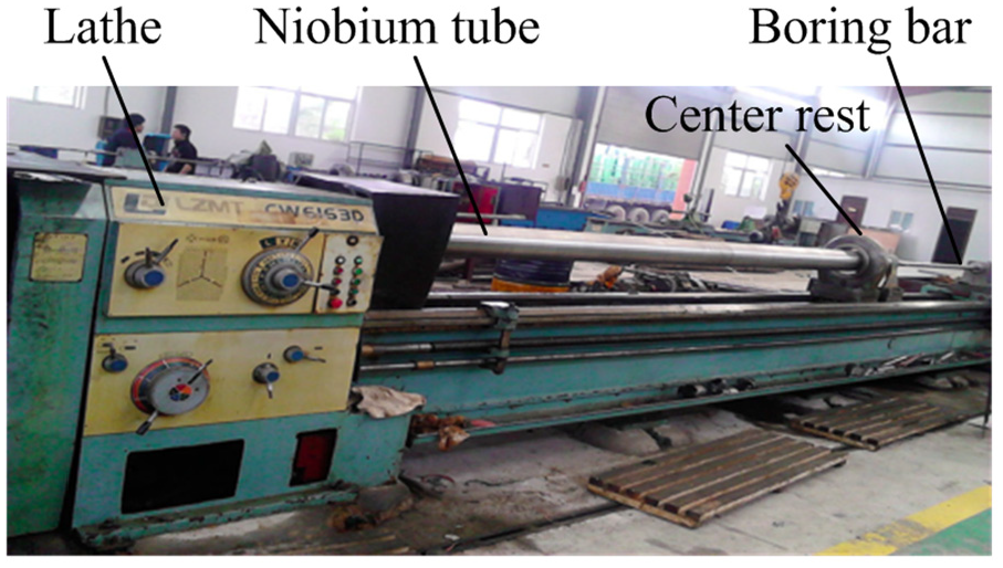
Deep-hole boring machine.
The geometric parameters of the boring tool are shown in Table 1, including rake angle (γ), relief angle (α), inclination angle (λ), and cutting edge angle (κr). To reduce the deformation of the chips, the range of the rake angle is from 5° to 20°. To avoid the friction action caused by the spring back of the inner hole with the rear face of the boring tool, the relief angle should be set relatively large and the range is from 5° to 25°. Meanwhile, to ensure the surface quality of the machined inner hole and reduce the self-excited vibration generated by the operating system and the bending of the niobium tube, the range of the inclination angle is from −20° to 0° and the cutting edge angle is from 0° to 25°. The material of cutting tool is YG8.
The specific process parameters in step I.
Based on the aforementioned principles, the basic parameters of the cutting tool were designed, and the rotation speed of the workpiece and the feed rate of the cutting tool were selected. The geometric parameters of the cutting tool include the rake angle (γ), relief angle (α), inclination angle (λ), and cutting edge angle (κr). The process parameters include the rotation speed (n), feed rate (f), back cutting depth (ap), and changed tool position. Tool wear, chip morphologies, and hole surface roughness were studied based on the experimental results. JSM-6390A scanning electron microscopy (SEM) and energy dispersive spectroscopy (EDS) were used to observe the wear profile of the tool, and the element composition analysis was performed on the tool wear zone. The SEM is a JSM-6390A scanning electron microscope manufactured by JEOL Ltd, and the EDS spectrometer is part of SEM. The inner hole surface roughness was measured by TIME3230 roughness tester. The hole-axis deflection was calculated according to the wall thickness (measured by ultrasonic thickness meter TIME 2123) at each measurement point.
Experiment and results analysis
To machine the pure niobium tube effectively and smoothly, two schemes for deep-hole boring of pure niobium tube were investigated. Each scheme includes three steps. In each step, the tool wear, chip morphologies, and hole surface roughness are analysed, and then the geometric parameters of the cutting tool and process parameters are continuously adjusted in the subsequent steps, and optimal parameters are finally obtained.
Scheme 1
Scheme 1 was designed to study the influence of geometric parameters of the cutting tool and process parameters on hole surface quality, which is main evaluation index used to assess the deep-hole boring of the pure niobium tube. In this scheme, it includes three steps shown in the following section. In step I, the geometric parameters of cutting tool are constant, the cutting conditions and chip morphology were observed under different rotation speed and feed rate, and the cause of the cutting tool wear was analysed. Based on the analysis results of step I, the geometric parameters of cutting tool and process parameters were improved in step II, and the cutting conditions, sharp tremor position, and tool wear were analysed. Based on the results of step I and step II, tool wear was studied and the geometric parameters of cutting tool were adjusted in step III. In addition, the hole-axis deflection and hole surface roughness were also investigated.
Step I
Since the pure niobium tube has the characteristics of large cutting force, high cutting temperature, tough chips, and tool wear in the boring process, the back cutting depth was set to 1.5 mm. The geometric parameters of cutting tool in the experiment were as follows: rake angle 15°, relief angle 21°, inclination angle 0°, and cutting edge angle 16°. The specific process parameters are shown in Table 1.
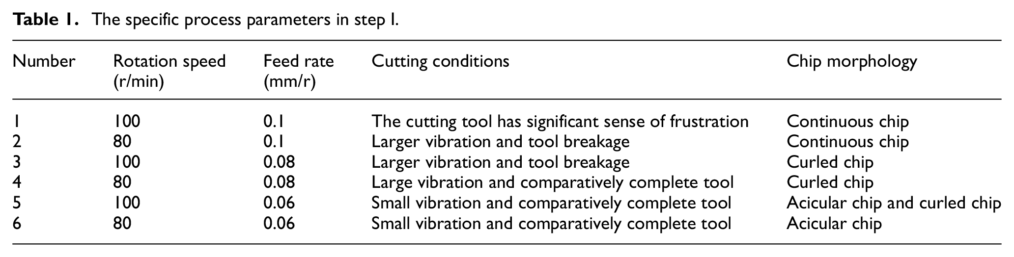
The experimental results showed that process parameters had a direct effect on the tool wear and the chip morphology. When the geometric parameters and rotation speed were constant, the vibration produced at the feed rate of 0.1 mm/r was significantly higher than that of 0.06 mm/r. The strong vibration leads to the tipping of the cutting edge in the boring process. Figure 2 shows the tipping of rake face and rear face at the feeding rate of 0.1 mm/r. This is caused by the presence of hard spots on the inner wall of the pure niobium tube.
Cutting tool tipping at the feeding rate of 0.1 mm/r: (a) rake face and (b) rear face.
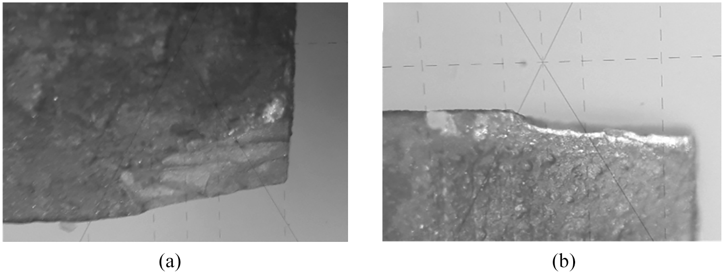
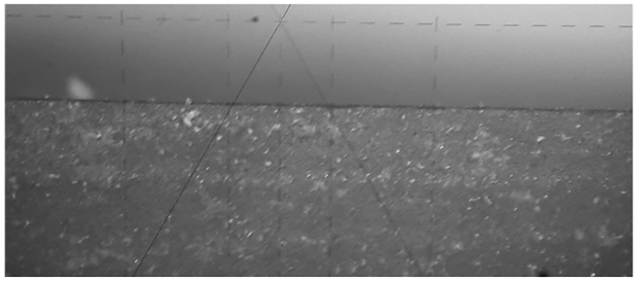
When the feed rate is 0.06 mm/r, a small part of crescent-shaped wear region is produced on the rear face as shown in Figure 3. This is caused by adhesion wear. 22 In the boring process, the boring system will generate self-excited vibration, forcing the rear face and the chip surface contact with each other. The chips will undergo a plastic deformation under the interaction of the tool and the niobium tube; the deformed parts can be transferred to the tool and bonded on the rear face under the action of cutting heat. The adhesions are extremely unstable and can be detached from the rear face under the pressure of the tool and niobium tube. Meanwhile, some of the tool materials are also taken away, 23 thereby leading to an adhesion wear. Therefore, the feed rate is set to 0.06 mm/r in the subsequent experiments to ensure the boring quality.
Wear of the rear face.
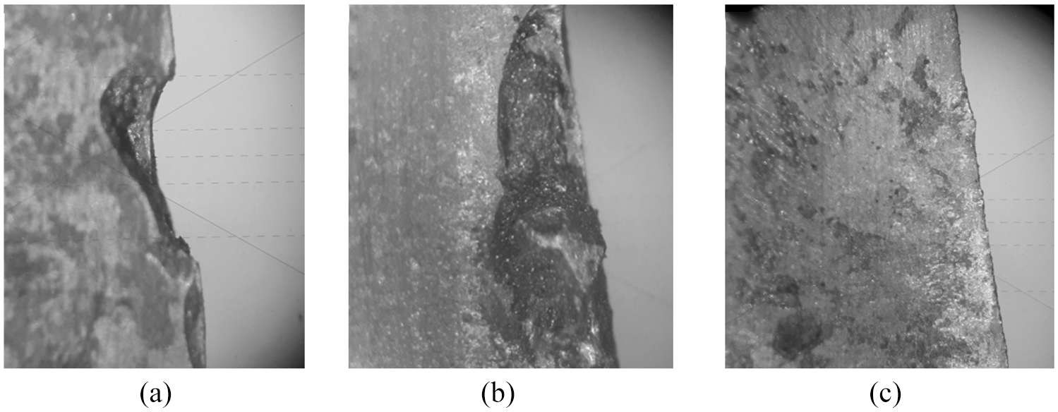
The chip morphology includes three types of continuous chips, curled chips, and acicular chip, which are shown in Figure 4. When the feed rate is 0.1 mm/r, the continuous chips were produced. It should be avoided during the boring process because it can cause a lot of pressure on the cutting tool and is easy to cause blocking in the chip removal space. When the feed rate is 0.08 mm/r, the curled chips were generated. A large amount of the curled chips put huge pressure on the rake face, which leads to the wear and failure of the rake face of the cutting tool. When the feed rate is 0.06 mm/r and the rotation speed is 80 r/min, the acicular chip is formed, which has the advantages of small volume and easy discharge.
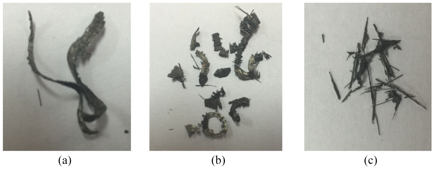
Chip morphology: (a) continuous chips, (b) curled chips, and (c) acicular chip.
Step II
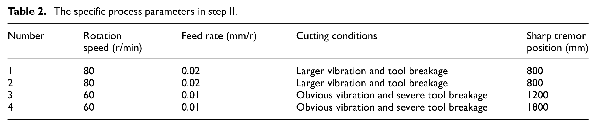
After the first step of boring process, the inner wall of the niobium tube has been flattened. There will be no damage to the tool caused by the unevenness of the inner wall and the material inhomogeneity in the subsequent machining. Therefore, in order to improve the boring efficiency, the back cutting depth is increased and set to 5 mm. Meanwhile, to ensure the impact resistance and durability of the cutting tool, the rake angle and relief angle are decreased, and the inclination angle and the width of the flute are increased. The geometric parameters of cutting tool were as follows: rake angle 5°, relief angle 5°, inclination angle −19°, and cutting edge angle 16°. The specific process parameters are shown in Table 2. Because the back cutting depth is larger than that in step I, the smaller rotational speed and feed rate were used to ensure the initial processing smoothly. The feed rates of 0.02 and 0.01 mm/r are used.
The specific process parameters in step II.
In the initial stage of the second step, the boring of the niobium tube could be performed smoothly, and the cutting tool was not damaged during the process. However, the small rake angle and relief angle made the crescent-shaped adhesion wear formed on the rake face and rear face. As the boring process continued, the boring system produced a sharp tremor that caused the cutting tool to break; hence, the entire boring process was forced to stop, as shown in Figure 5.
Damage of the cutting tool.
The results of the second step show that if the back cutting depth is too large, a notch will occur on the tool, and the cutting tool will be damaged as the notch continues to expand.
Step III
In order to ensure the coaxially of the niobium tube, the excircle of the niobium tube was turned first before the third step of the boring process so that the outer diameter of the niobium tube is turned to 165 mm, and then the straightening was performed, and the pull boring process with the back cutting depth of 1.25 mm was finally performed.
Compared with the first step, the rake angle, the relief angle, and the assistant deflection angle were reduced to ensure the strength of the cutting tool, and the inclination angle was increased to improve the chip removal. The geometric parameters of cutting tool were as follows: rake angle 6°, relief angle 11°, inclination angle −2°, and cutting edge angle 11°. The rotation speed is 80 r/min, and the feed rate is 0.06 mm/r.
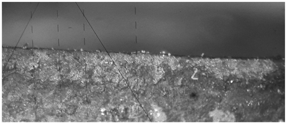
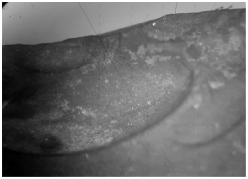
The wear of the cutting tool in the third step is shown in Figure 6. A very long wear band is formed on the minor cutting edges of the cutting tool. This is caused by the chatter and grinding effects produced during the boring process.
Wear of the minor rear face of the cutting tool.
Hole-axis deflection
The whole pure niobium tube was divided into 12 sections, and four points were evenly selected to measure in each section. The hole-axis deflection is shown in Figure 7. In step I and step II, the first point and second point have a large abrupt change in the image of hole-axis deflection. This is because that the dimension of the niobium tube’s excircle is not standard. So the excircle was turned before the third step, and the hole-axis deflection was significantly reduced in the third step. Therefore, the pull boring could automatically realize the axis deflection correction. And there are only two obvious inflection points on the hole-axis deviation curve in step III.
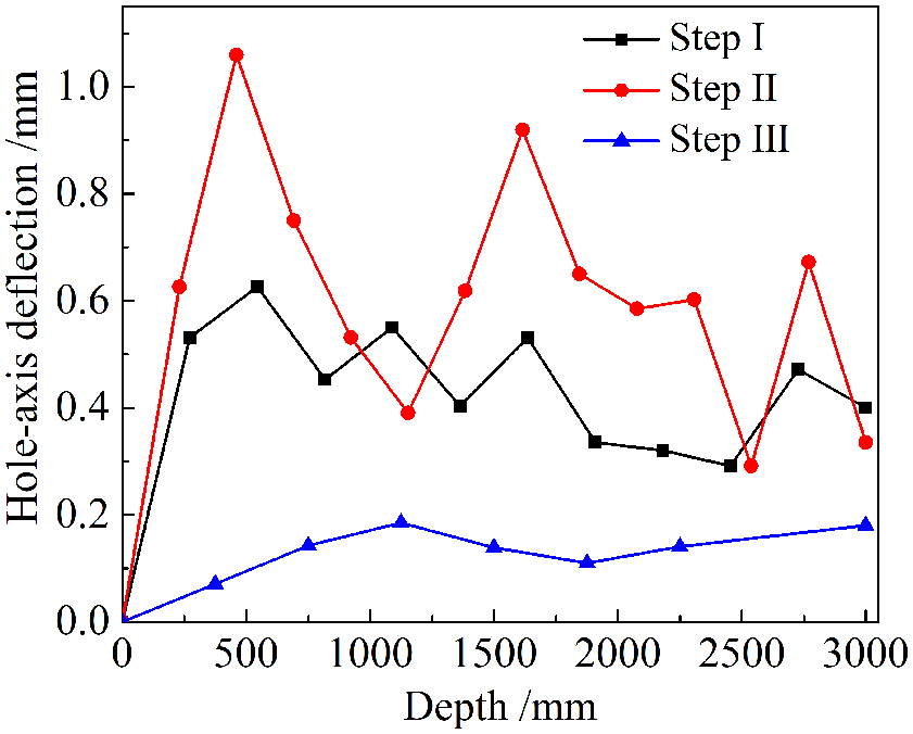
Hole-axis deflection of scheme 1.
Inner hole surface roughness
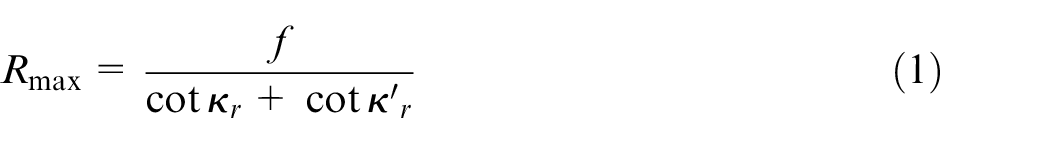
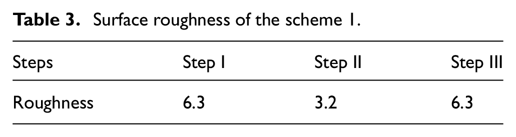
The surface roughness of three steps is shown in Table 1. After the third step, the roughness of the niobium tube is 6.3 μm, and the inner hole surface is extremely unsmooth. The roughness is much higher than that in the second step (3.2 μm). The surface roughness is mainly affected by the cutting edge angle, assistant deflection angle, feed rate, and material properties. The influence of the cutting edge angle, assistant deflection angle, and feed rate on surface roughness can be expressed by equation (1). Axial height (Rmax) of the residual area also has a direct impact on the surface roughness. Increasing the cutting edge angle while keeping the feed rate constant or increasing the feed rate with constant cutting edge angle causes increase in the axial height, which results in an increase in the surface roughness. The experimental results in Table 3 are consistent with equation (1)
Surface roughness of the scheme 1.
In addition, the surface roughness is affected by the plasticity of the niobium. In the third step, the minor cutting edge of the cutting tool and the niobium tube are in contact with each other. Due to the high plasticity of the niobium, the adhesion wear was formed on the minor cutting edge of the tool and scratched the inner wall surface which had been machined. In the second step, the back cutting depth is larger than in the other steps; this makes the feed rate and the rotation speed to decrease, and the self-excited vibration generated in the system is reduced, thereby the mutual contact between the minor cutting edge of the tool and the niobium tube is reduced effectively, so the inner hole quality is ensured. This result shows that the quality of the machined inner hole surface is not only affected by the back cutting depth but also related to the grinding effect of the minor cutting edge of the tool.
Scheme 2
In scheme 2, there are also three steps included. Each step is similar to the steps explained in scheme 1, and more studies are conducted to improve parameters to achieve better hole surface quality.
By comparing the results of different steps from scheme 1, it is indicated that the back cutting depth cannot exceed 5 mm to reduce the grinding effect caused by the minor cutting edge of the cutting tool. Rotation speed and feed rate were set at 80 r/min and 0.06 mm/r, respectively.
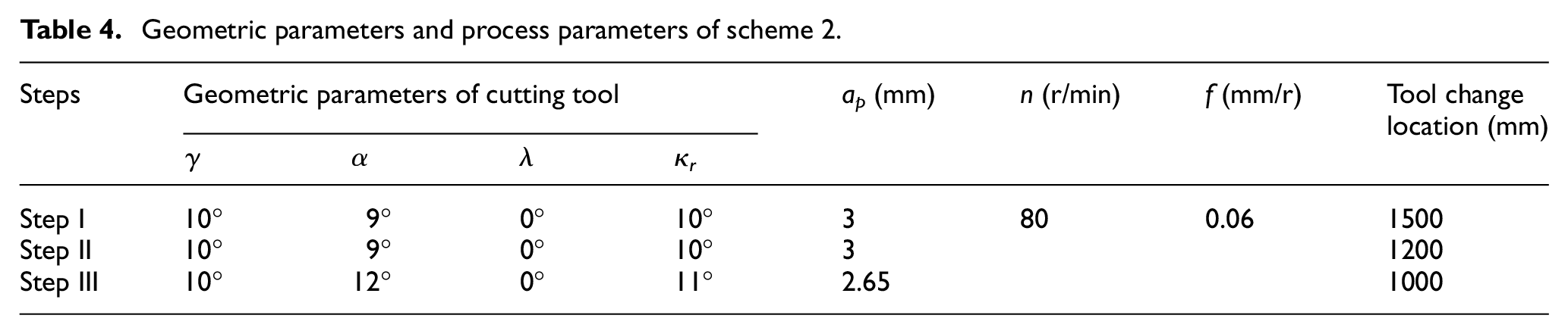
The geometric parameters of the cutting tool and process parameters are shown in Table 4. To protect the cutting tool and inner hole surface quality, the boring tool was changed at different positions during the three steps. The changed positions were at the tube length of 1500, 1200, and 1000 mm in the first, second, and third steps, respectively. Because the chip morphology and hole-axis deflection are similar to those of the scheme 1, only the tool wear and inner hole surface quality are analysed in this section.
Geometric parameters and process parameters of scheme 2.
Tool wear
Figure 8 shows the wear pattern of cutting edge at different steps in scheme 2. The cutting tool has tipping on the cutting edge and tool nose in the first step and second step. And the cutting tool has normal wear and no tipping occurs in the third step. Figure 8(a) shows the tipping patterns of the cutting edge at the changing positions of 1500 mm in step I. Figure 8(b) shows the tipping patterns of the cutting edge at the changing positions of 1200 mm in step II. The tipping was caused by the cohesive wear which was induced by the high plasticity of niobium. A certain amount of material build-up was produced on the rake face of the cutting tool during the pull boring, leading to a smaller actual contact area and larger pressure between the cutting tool and the niobium tube, which causes cracks at the cutting edge and rake face. With the proceeding of the boring process, the built-up edge becomes larger, leading to a wider wear band and greater surface roughness. And the cutting force and cutting temperature will continue to rise, and the material build-up continues to act at the cutting edge, which lead to a tool tipping even failure.
Wear pattern of cutting edge at different steps: (a) step I, (b) step II, and (c) step III.
To analyse the cohesive wear of the cutting tool, element composition analysis was performed on the wear zone of cutting tool. It was clearly seen that there is an obvious wear zone in the tipping area and a clear colour distortion on the rake face. The measurement regions of 001 and 002 are selected to analyse the energy spectrum in Figure 9.
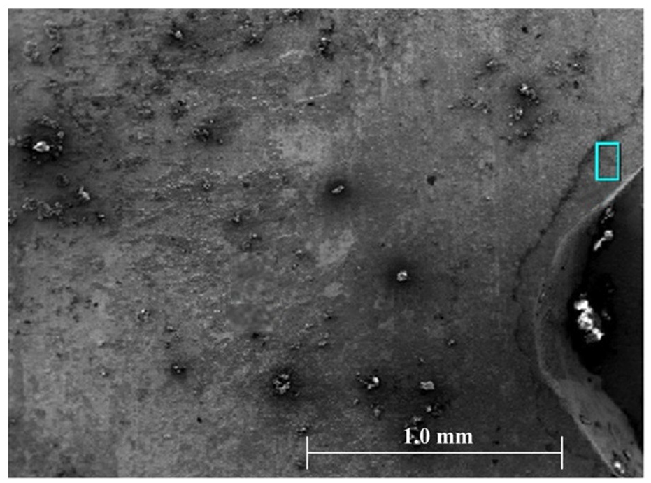
EDS analysis of cohesive wear of the cutting edge in step I.
Figure 10 is the energy spectrum analysis of the measurement regions 001 and 002. It can be seen that the cutting edge is covered with element niobium. During the boring process, the chips are in contact with rake face of cutting tool and make it possible to diffuse niobium into the cutting tool under high temperatures. Thus, it leads to a large amount of niobium elements generated on the rake face, weakening the material properties and accelerating wear of the rake face, and eventually causes the cutting edge to wear or tipping. The cutting edge with tipping produces a cutting action on the inner hole of the niobium tube due to the self-excited vibration, and the built-up edge is produced and falls off, and then some of the tool materials are taken away with the deciduous built-up edge. Afterwards the new built-up edge is formed on the rake face of the cutting tool and then continues to fall off. It also can be seen that if the cutting tool continues to machine after tipping, it will cause serious damage to the cutting tool and the machined surface.
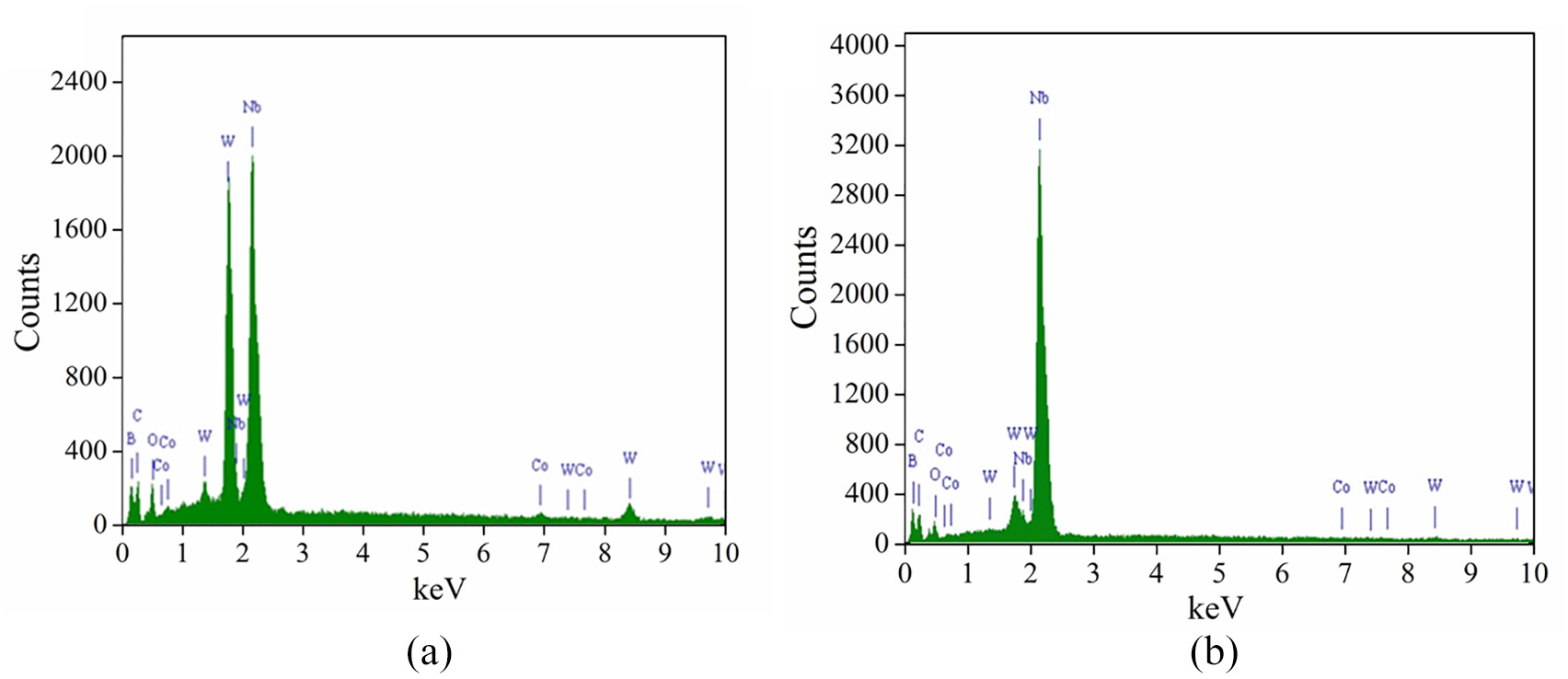
Energy spectrum analysis of regions (a) 001 and (b) 002.
At the measurement region 002, the surface is also covered with element niobium. The unbroken chips flow through this area, and the cutting tool is pressed on those chips, and then a large amount of element niobium remains on the rake surface of the tool.
Figure 11 shows the material build-up on the cutting edge with cohesive wear. Region 003 was selected for energy spectrum analysis and the result is shown in Figure 12. A large amount of niobium was observed on the cutting edge because of the material build-up. Using the cutting tool with the material build-up to cut the workpiece will lead to a continuous growth of the material build-up. When it reaches a certain height, it will fall off under the action of external force or vibration, and thus the cohesive wear occurs. This is consistent with the results of the first step. And the formation of build-up edge is a cyclic process.
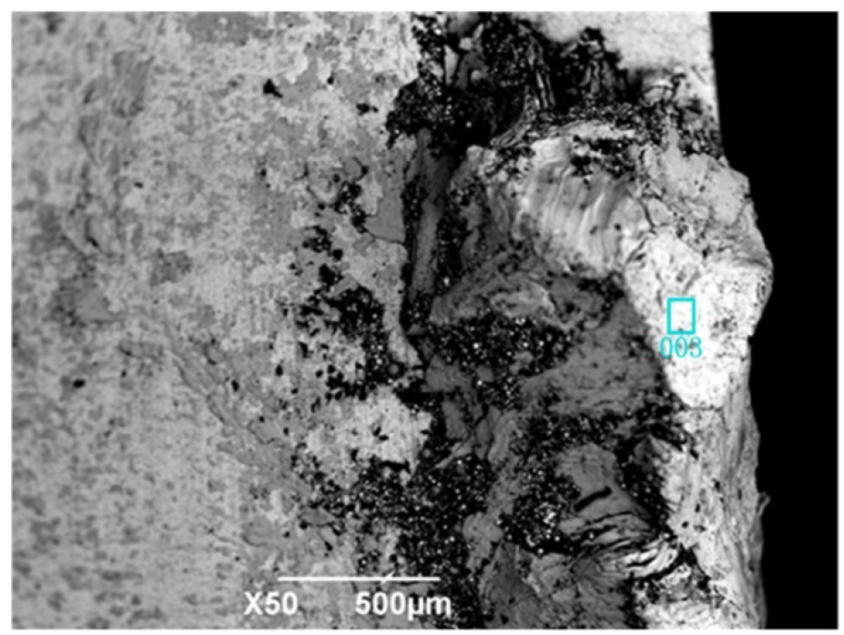
EDS analysis of cohesive wear of the cutting edge in step II.
Energy spectrum analysis of region 003.
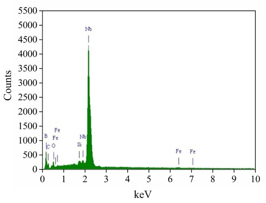
As shown in Figure 8(c), the tool wear occurs normally in step III and no tipping occurs. An appropriate increase in the relief angle reduces the friction and contact length between the cutting tool and niobium tube, thus reducing the friction and wear on the rear face. The results show that if the process parameters and geometric parameters of the cutting tool are reasonable, the niobium tube could be machined completely without breaking the tool in the pull boring process. The element variation on the rake face was observed by electron microscope. Region 004 was selected for energy spectrum analysis and the result is shown in Figure 13. The surface is covered with element niobium. The material build-up is formed on the rear face. When the material build-up is big enough to fall off the surface, some of the tool materials are taken away simultaneously and more niobium material begin to stick to the tool surface for further cutting.
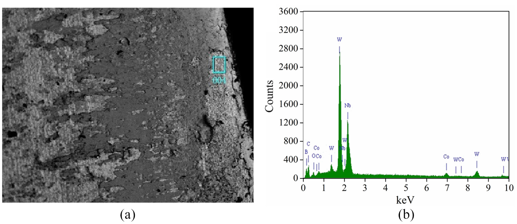
Cohesive wear of the cutting edge in step III: (a) region 004 and (b) EDS analysis.
Hole surface roughness
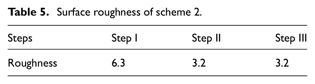
Table 5 shows the hole surface roughness of scheme 2. The finished hole surface roughness is 3.2 μm. The reason is similar to the one explained in scheme 1.
Surface roughness of scheme 2.
Conclusion
According to the properties of pure niobium tube, the geometric parameters of cutting tool and process parameters were designed. Two kinds of pull boring schemes were designed to optimize the geometric parameters of the tool and process parameters and following conclusions are obtained:
The optimal tool geometric parameters obtained by comparative analysis of two experimental schemes are as follows: the rake angle 10°, the relief angle 12°, the inclination angle 0°, and the cutting edge angle 11°.
The optimal boring process parameters are as follows: rotation speed 80 r/min, feed rate 0.06 mm/r, tool changing position at 1000 mm, and back cutting depth in the range of 2–5 mm. The back cutting depth cannot be too large or too small. When the back cutting depth is less than 2 mm, then the machined inner hole is rough; if it is larger than 5 mm, the growth of the built-up edge and the tool wear will be increased, and the chips cannot be quickly removed from the workpiece.
The tool’s relief angle must be increased to avoid the grinding action of the minor cutting edge on the inner hole surface. Otherwise it will increase the roughness of the inner hole.
The inclination angle of the tool cannot be set too large because large inclination angle will make a large amount of chips accumulated between the rake face and the unprocessed surface, and the built-up edge will easily occur, leading to a bad influence on the tool.
Geometric parameters of the cutting tool and process parameters have important influences on the tool wear, chip morphologies, hole-axis deflection, and hole surface roughness.
Footnotes
Appendix
Declaration of conflicting interests
The author(s) declared no potential conflicts of interest with respect to the research, authorship, and/or publication of this article.
Funding
The author(s) disclosed receipt of the following financial support for the research, authorship, and/or publication of this article: This research was funded by National Science Foundation of China (Grant No.51675414) and Natural Science Foundation of Shaanxi Province of China (Grant No. 2018JQ5002).