
Abstract
Poor surface quality and rapid tool wear are the main problems in micro-cutting of Inconel 718. In this study, a novel hybrid machining method named laser-induced oxidation assisted micro-milling is proposed to solve the aforementioned problems. A loose oxide layer and a relatively flat sublayer are formed on the material after laser irradiation. Under optimized laser parameters with a scanning speed of 1 mm/s and an average laser power of 4.5 W, the thicknesses of the oxide layer and the sublayer are 24 and 18 μm, respectively. The influence of cutting parameters on milling force, surface roughness, surface quality, and top burr size is studied in detail. Cutting force and thrust force in the proposed hybrid machining process are lower than those in the conventional micro-milling. Results show that for the investigated range of parameters, the optimal feed per tooth and depth of cut in the hybrid process are 3 μm/z and 3 μm, respectively. When using the optimal parameters, the surface roughness of the machined slot bottom is 108.5 nm. The top burr size on the up-milling side and the down-milling side is 26.8 and 36.2 μm, respectively. In addition, the tool wear mechanism is coating delamination in hybrid process, whereas chipping, coating delamination, tool nose breakage, and adhesion are the main tool wear mechanism in the conventional micro-milling. For the same amount of material removal, the proposed hybrid process can decrease the tool wear and enhance the service life of the micro-end mill as compared to conventional micro-milling.
Introduction
Inconel 718 is one of the preferred materials in the aerospace industry. However, it suffers from poor micro-machinability because of having low thermal conductivity and high chemical affinity for many cutting tool materials.1–3 Lithographic methods such as photolithography, focus ion beam, and X-ray lithography are the most common fabrication technologies applied at the micro- and nano-scales. 4 While, these methods have extensive applications in the industry and are applicable only to a few materials such as silicon or glass. 5 Producing micro-parts from other engineering materials like metals, alloys, and composites is a challenging task for them. In addition, these techniques offer low efficiency and minimized flexibility accompanied by high cost, and are merely appropriate for micromachining of plane geometries. 6 Hence, other nontraditional methods have been proposed for machining of micro-components and micro-parts. In particular, micro-electrical discharge machining (EDM) and micro-electrochemical machining (ECM) have been have been extensively researched for the micromachining of Inconel 718.7,8 However, these technologies are limited by the challenges of severe electrode wear, low machining speed, and increased cost. Ultrasonic-assisted hybrid machining (USM) is considered as an alternative process for the fabrication of Inconel 718. However, this process suffers from drawbacks such as slow machining efficiency, and high machining and tooling cost. 9 In addition, laser micromachining (LMM) allows the potential of achieving micro-features, which is the case in other machining processes like micro-milling by micro-tools and micro-EDM/ECM. However, LMM could induce thermal damage on the machined surface and produce a recast layer as well as heat-affected zone, thereby deteriorating surface quality and dimensional accuracy. 10
In the field of micro-mechanical fabrication, micro-milling has been consistently gaining attention over the years. Micro-milling embraces many advantageous characteristics in terms of flexibility, cost efficiency, repeatability, and high form accuracy.11–13 In addition, it serves as a primary means for shaping three-dimensional micro-parts out of various materials, particularly metals and metallic alloys. A summary from a few of relevant works is presented as follows. Ucun et al. 14 investigated the effect of coating material on the cutting performance in the micro-milling of Inconel 718. The results showed that the diamond-like carbon (DLC)-coated tools exhibit better performance than uncoated tools in terms of surface quality, tool wear, and burr formation. Moreover, the former reduced the cutting force comparatively. Lu et al. 15 established a surface topography simulation model of micro-milling Inconel 718 and analyzed the micro-milling surface roughness and the formation mechanism of the surface topography. From comparisons of experimental measurement, they found that built simulation model can predict surface topography accurately. Aslantas and Cicek 16 carried out a study of the effects of different cooling/lubrication strategies on burr formation, surface quality, and tool wear in micro-milling of Inconel 718. They concluded that the use of minimal quality lubrication was advantageous in terms of tool wear, burr formation, and surface roughness over other lubrication methods.
Despite many potential advantages of micro-milling, its applications on wider scale are currently limited by the equipment and tool properties. In particular, low stiffness and limited flexural strength of a miniature tool restrict the cutting performance of micro-milling difficult-to-cut materials. When the strength of the micro-tool is lower than the stress generated by the cutting force, the fracture of the micro-tool would occur in the machining process. 17 While machining at a microscopic level, the hardness of the materials to be machined results in higher cutting force, thereby producing adverse impacts on the dimensional precision and accuracy of the machined micro-feature.
The aforementioned issues can be overcome by adopting a hybrid processing method named as laser-assisted micro-milling (LAMM), as first proposed by Singh and Melkote. 18 LAMM consists of a continuous wave fiber laser integrated with a mechanical micro-machine. The laser beam is applied on the workpiece material just ahead of the micro-tool, which in turn reduces the flow strength thereby causing a reduction in the cutting force and tool deflections. Melkote et al. 19 indicated that LAMM improved the dimensional accuracy and machined surface quality for hardened materials. Anderson et al. 20 reported that 25% decrease in specific cutting energy was obtained by providing local heating of Inconel 718 with a laser beam in LAMM. As a result, there was a significant improvement in machining efficiency and economy. In addition, the cutting forces and the tool wear are superior to those in conventional micro-milling (CONM). 21 However, burr heights and surface roughness are found to increase in LAMM. 22 A heat-affected zone exists in the machined micro-feature due to nonoptimal laser parameters, which leads to poor surface quality.
In this study, a novel hybrid process of laser-induced oxidation assisted micro-milling (LOMM) is proposed, and the discussion presented above follows that poor machinability and rapid tool wear can be significantly solved in LOMM. Up till now, any research work addressing micro-scale LOMM of Inconel 718 has not been reported so far. The LOMM experimental setup for micro-slotting is established. Cutting forces, surface quality of the machined slot, burr formation, and tool wear mechanisms are investigated. For comparison purposes, the CONM experiments are also carried out.
Experimental setup
Material and micro-end mill
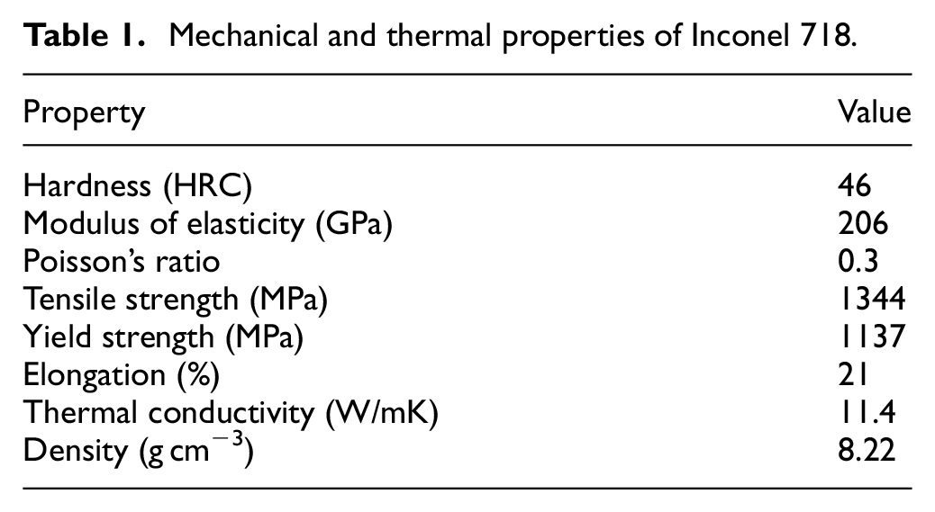
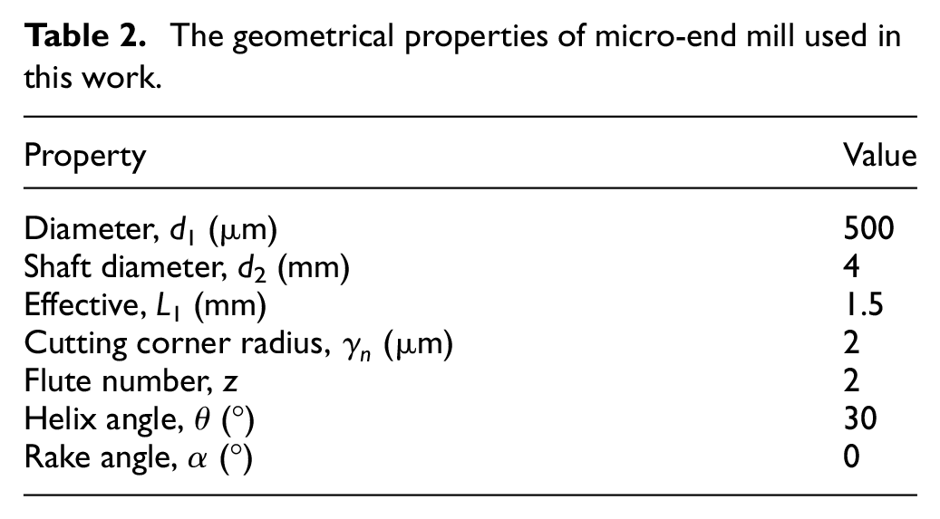
In this work, rectangular blocks of Inconel 718 with a hardness of 44 HRC are reprepared in the dimensions of 35 mm × 5 mm × 5 mm. Workpiece surfaces to be machined are divided into the identical blocks with the assistance of wire electric discharge machine and then polished with abrasive papers according to standard metallographic techniques. The mechanical properties of Inconel 718 are listed in Table 1. A two-fluted cemented carbide micro-end mill coated with a thin layer of CrTiAlN is utilized as a cutting tool. The hardness and the thickness of the coating are 3600 HV and 3 μm, respectively. The geometrical properties and the morphology of the micro-tool are presented in Table 2 and Figure 1, respectively.
Mechanical and thermal properties of Inconel 718.
The geometrical properties of micro-end mill used in this work.
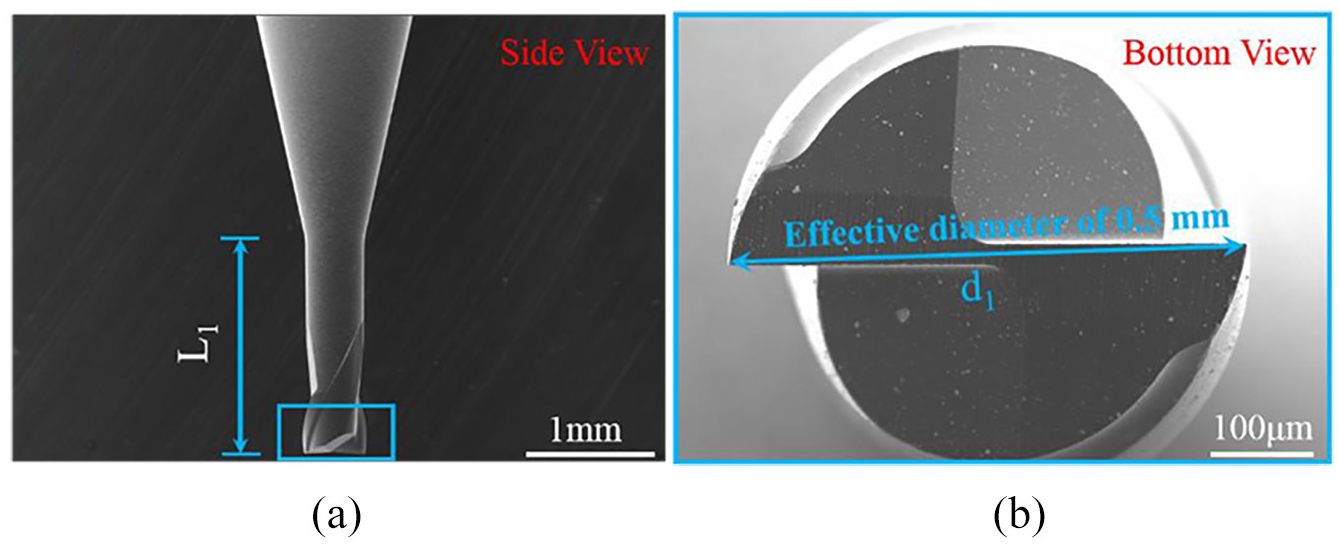
SEM morphologies of the micro-end mill in this work from: (a) side view and (b) bottom view.
LOMM process
Figure 2 shows the schematic diagram of the proposed LOMM process. Inconel 718 material surface is induced by a pulsed laser with the assistance of oxygen which forms the loose oxide layer. Due to the heat-affected mechanism under the laser-induced oxidation, a sublayer is generated between the oxide layer and the substrate. In the compound process, high purity industrial oxygen (99.2%) with a flow rate of 5 L/min has been utilized in the oxidized reaction. Subsequently, the micro-cutter can remove the loose oxide layer easily. With the removal of the oxide layer, the exposed sublayer further generates a new oxide layer after the oxidized reaction occurs again. After several loops of the aforementioned removal mechanism, the laser setup and assisted gas nozzle need to be shut down. Finally, the sublayer and the thin substrate are removed by the micro-tool of machining instrument, thus obtaining the micro-feature finish.
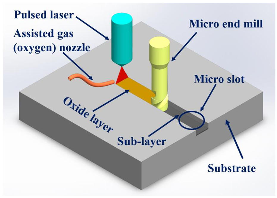
Schematic diagram of LOMM process.
Design of laser-induced oxidation and micro-milling experiments
To demonstrate the effectiveness of the proposed new compound machining method, full-immersion slot-milling experiments of cemented carbide are carried out using a high-speed multifunction precision micro-milling machine equipped with a nanosecond pulse ytterbium-doped fiber laser (YLP-1/100/20, IPG Photonics Corporation), as presented in Figure 3. The laser is fixed on a mechanical z-axis linear stage with an adjustment accuracy of 2 μm, as shown in Figure 4.
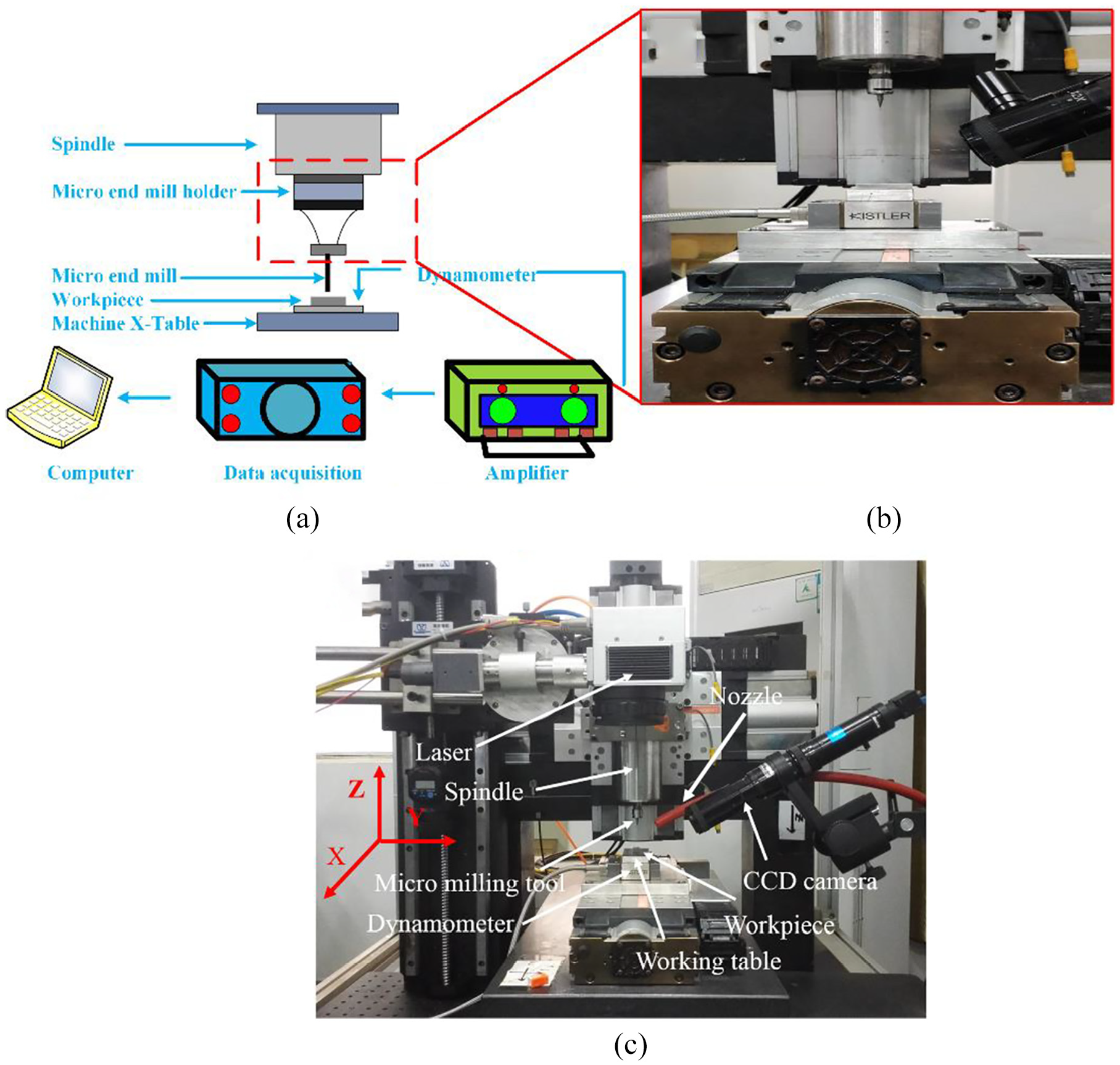
(a, b) Configuration of measuring milling force and (c) experimental setup for micro-milling experiments.
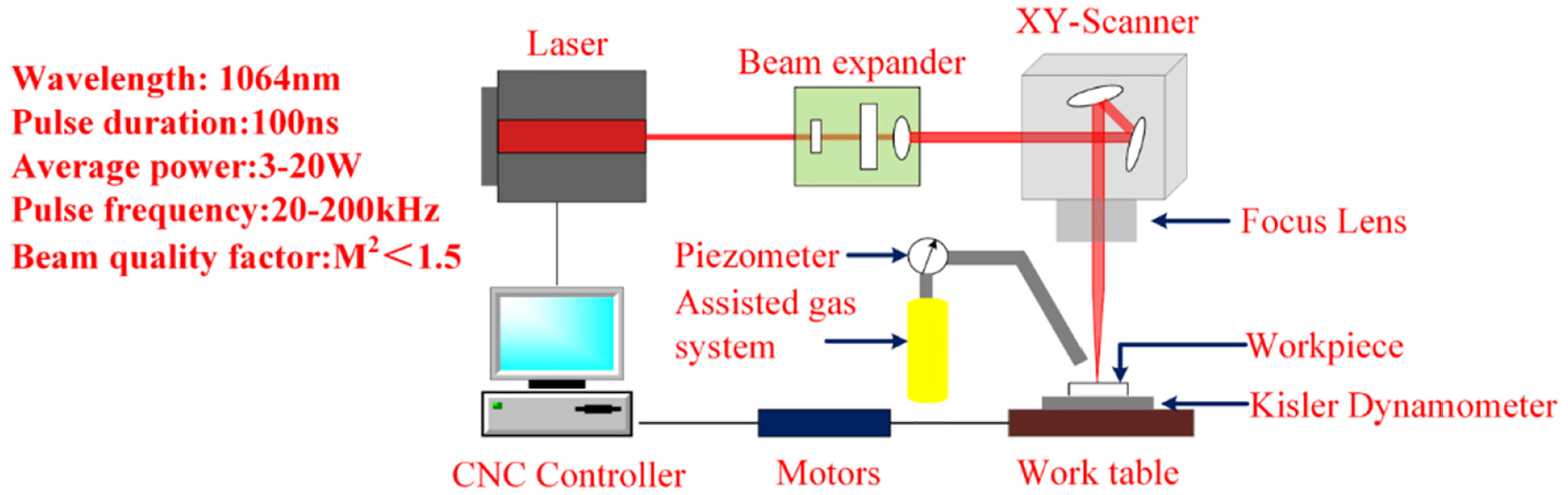
The schematic diagram and specification of the laser-induced oxidation system.
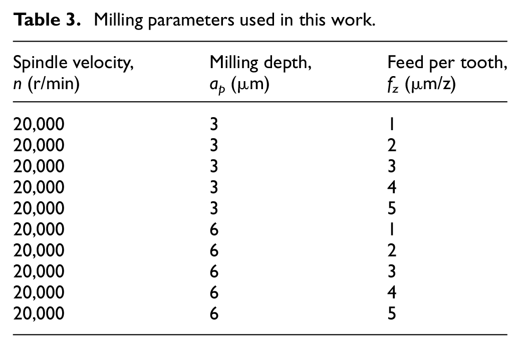
For optimal results in the preliminary experiments, an average laser beam power of 4.5 W and a scanning speed of 1 mm/s are used in this work. A series of tests concerning LOMM and CONM processes are carried out, and the milling parameters of micro-slotting tests are summarized in Table 3. In each experimental run, straight micro-slots with the width of 0.5 mm and the length of 5 mm are formed in dry conditions.
Milling parameters used in this work.
Characterization
A scanning electron microscope (SEM; S4800, Hitachi) is used to observe the microstructure and morphology of the oxide layer and sublayer, surface quality, burr formation, and the morphology of the micro-cutting tool. A three-dimensional (3D) laser scanning microscope (LSM 700, Carl Zeiss AG) is used to observe the morphology of the machined surface. The milling force in micro-milling process is measured with a piezoelectric dynamometer (9256C1, Kistler Group). The maximum sampling frequency and the threshold force level are 30 kHz and 0.002 N, respectively.
Results and discussion
Oxidation behavior of Inconel 718 under laser irradiation
Some studies have found that Inconel 718 can be oxidized at a high temperature, thereby causing phase changes and forming oxides on its surface. 23 The formed oxides of the oxide layer mainly include Cr2O3, Fe2O3, and FeNbO4. The surface morphology of Inconel 718 before and after laser-induced oxidation is shown in Figure 5(a), where it can be seen that the workpiece surface produces a loose oxide layer under the process of laser-induced oxidation. In addition, the microstructure of oxide layer is presented in Figure 5(b) and the loose oxides are also expected. This indicates that Inconel 718 surface can be machined easily with a low cutting load. The sublayer shown in Figure 5(c) is a heat-affected zone produced after laser-induced oxidation, which is based on removing the oxide layer using ultrasonic cleaning equipment for 5 min. After removing oxides, some adhesive residues (point A in Figure 5(c)) found on the surface of the sublayer.
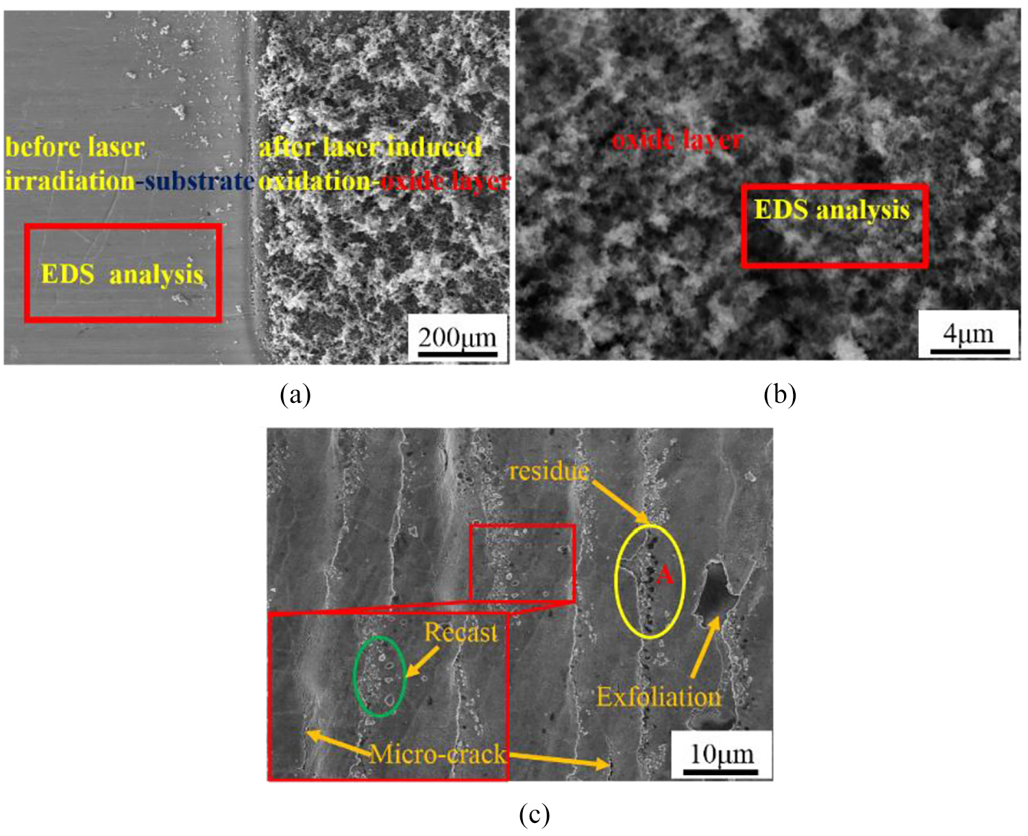
Surface morphology of (a) the material surface, (b) the oxide layer, and (c) the sublayer.
Figure 6(a) presents the results of energy-dispersive X-ray spectroscopy (EDS) analysis in the substrate. EDS analysis of the oxide layer is shown in Figure 6(b). Compared to the substrate, the EDS analysis of oxide layer mainly reveals the occurrence of oxygen element and the contents of other original elements are decreased after laser-induced oxidation. Figure 6(c) shows the analysis of EDS performed at point A given in Figure 5(c). The result reveals that residue observed in the image is indeed composed of oxides and the size of adhesive oxides is very small. These oxides are removed by the ultrasonic cleaning machine, which results in the formation of micro-crack and exfoliation in the sublayer surface. In addition, residual stress was induced when Inconel 718 cools down from the peak temperature to the normal room temperature, owing to the nonidentical thermal expansion coefficients. Consequently, the micro-crack is formed on the material surface of the sublayer.
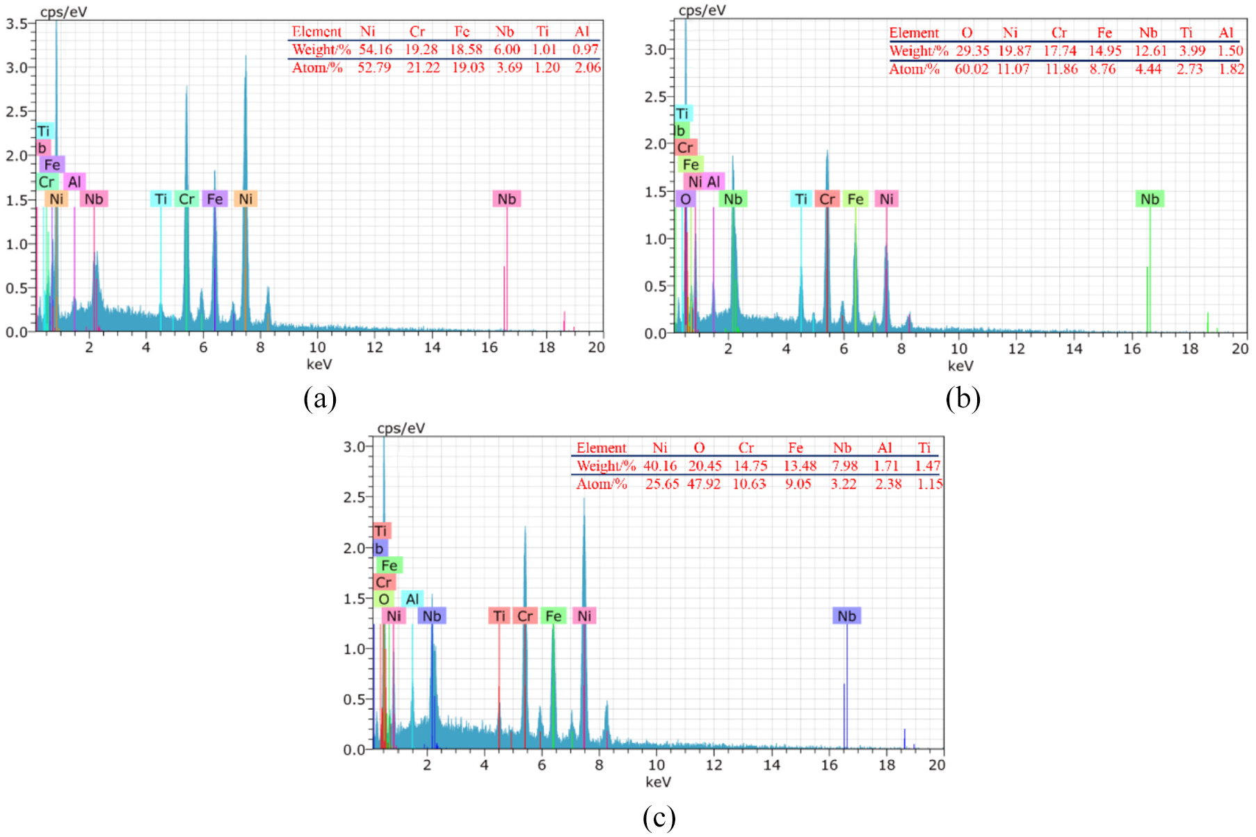
EDS analysis of (a) the substrate, (b) the oxide layer, and (c) the point A in the sublayer.
Furthermore, the surface of the sublayer is flat with the presence of adhesive oxide materials, as shown in Figure 5(c). Under a high temperature caused by laser radiation, a large amount of molten material is ejected, and after cooling down, it reshapes on the surface to form the microscopic recast. From cross-sectional measurement, the thicknesses of the oxide layer and the sublayer are 24 and 18 μm, respectively. The sublayer hardness is 26 HRC, which is lower than that of the substrate. This indicates that the machinability of the Inconel 718 material is significantly improved by laser-induced oxidation mechanism.
Milling force
Figure 7 presents the variations of milling force (cutting force (Fx) and thrust force (Fy)) with the different values of feed per tooth (fz) as well as the depth of cut (ap). It can be observed that the thrust and cutting forces increase gradually with an increment of the feed per tooth under the same depth of cut for both LOMM and CONM. Similarly, the thrust and cutting forces increase gradually by increasing the depth of cut, which is based on the feed per tooth. However, the resultant force magnitudes in LOMM are much lower than those in CONM under the same milling parameters. In addition, at ap = 3 μm and fz = 1 μm/z, the milling force in LOMM is relatively low, and the minimal levels of Fx and Fy are 0.6 and 0.5 N, respectively. In comparison, the values of Fx and Fy in CONM are 1.55 and 1.28 N, respectively. Under the identical depth of cut, variations of the cutting and thrust forces in LOMM with respect to the increment in feed are not obvious.
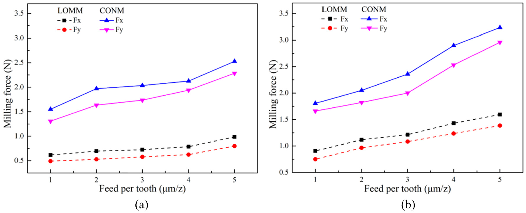
Changes in the milling force with variations of the feed per tooth at (a) ap = 3 μm and (b) ap = 6 μm.
In contrast, in the range from 3 to 5 μm/z of fz, the cutting force and thrust force significantly increase in CONM. It also indicates that the tool wear rate increases as the feed per tooth is increased, which results in higher milling force in CONM as compared to that in LOMM. At ap = 3 μm and the same level of increase in the feed per tooth, the cutting and thrust forces are reduced by 59% and 67% in LOMM, respectively, as compared to those in CONM. In addition, at ap = 6 μm, a drop of 51% and 43% is observed in the cutting and thrust forces, respectively, in LOMM when the feed per tooth was increased gradually. Thus, it is noted that the cutting load is extremely low in LOMM, where the loose oxide layer can be easily removed and the wear rate of the tool is much lower than that in approach of CONM.
Surface quality
In Figure 8, it can be seen that the surface roughness (Sa) is lower in LOMM than that in CONM with the increment of feed per tooth at ap = 3 μm and ap = 6 μm, respectively. In addition, Sa first increases and then decreases as the feed per tooth increases from 1 to 5 μm/z with an increment of 1 μm/z for LOMM and CONM under different cutting depths. When ap = 3 μm, surface roughness is found to increase with increasing fz in LOMM, and the varying amplitude of Sa is far lower than that in CONM. In addition, the minimum values of Sa in LOMM and CONM are 108.5 and 110.6 nm at fz = 3 μm/z, respectively. The surface roughness as a function of fz in LOMM is not significantly different from that in CONM at ap = 6 μm. At ap = 6 μm, the minimum value of Sa is 110.5 nm in LOMM and 111.9 nm in CONM, respectively. Moreover, the minimal value of surface roughness at ap = 3 μm is larger than that at ap = 6 μm, due to the augmentation in cutting depth. At low fz (the ratio of fz to cutting-edge less than 1), Sa in LOMM and CONM decreases at ap = 3 μm and ap = 6 μm, respectively. Sa increases sharply with fz for both milling methods while the ratio of fz to cutting-edge is more than 1 at ap = 3 μm and ap = 6 μm, respectively. The trend of the Sa decreasing with increasing fz explains the size effect and the minimal cutting thickness. At lower fz, a large rake angle (negative) dominates the cutting process in micro-milling—where the rake angle (negative) induces elastic recovery of the surface, plowing, and scratching effect. With increasing feed per tooth, plowing effect reduces, which results in the minimum elastic recovery of the machined workpiece and decreasing the size effect. In addition, the value of surface roughness reduces gradually and reaches a minimum. Subsequently, the removal material accumulates during micro-milling process, which gradually increases the surface roughness gradually. Furthermore, it indicates that the value of Sa in LOMM decreases smoothly because of the presence of a loose oxide layer in the front of cutting passes, resulting in very low cutting load and tool wear rate at low feed per tooth (ft < 3 μm/z). However, at a high federate (ft > 3 μm/z) for LOMM and CONM, the surface roughness at ap = 6 μm is far beyond that of ap = 3 μm because of the aggravation of tool wear rate.
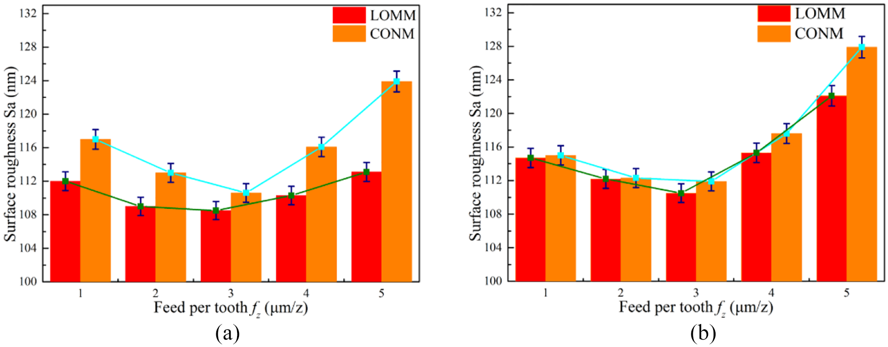
Variation of surface roughness (Sa) of the machined surface with increasing feed per tooth at (a) ap = 3 μm and (b) ap = 6 μm.
Since top burr is found to dominate the cutting process in both LOMM and CONM, it is necessary to investigate the correlation between the top burr size and cutting parameters. Figure 9 presents variations of the size of top burr over a range of fz from 1 to 5 μm/z for different depths of cuts. It is evident that change in the size of top burr with different feeds per tooth is significant.
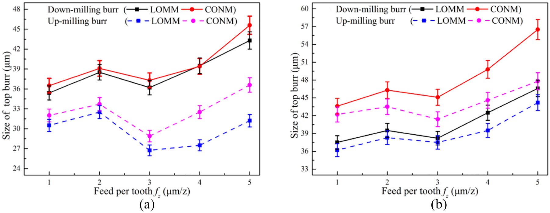
Size of top burr with respect to various feed per tooth at (a) ap = 3 μm and (b) ap = 6 μm.
In addition, the size of top burr on the down-milling side is larger than that on the up-milling side for both LOMM and CONM. In addition, top burr size in LOMM width is smaller than that in CONM on both up-milling side and down-milling side under the same cutting parameters. Yet, the size of top burr on each side reaches its first maximum when fz is approximately equal to the radius of cutting-edge in ap = 3 μm and ap = 6 μm. These observations are attributed to the rake angle reaching negative values, and the plowing and scratching effects dominate the machining process as a result of the ratio of fz to the radius of cutting-edge less than 1. In the size effect, the workpiece material cut does not form a chip, while easily generating a large top burr. Then, the size of top burr experiences its second variation when fz surpasses 3 μm/z. When the ratio of fz to the cutting-edge radius is more than 1, the cutting process becomes dominant and the generated top burr is removed by the micro-end mill rapidly. This leads to the top burr size attaining a minimum. At fz = 3 μm/z and ap = 3 μm, the top burr size on the up-milling and down-milling sides in LOMM is 26.8 and 36.2 μm, respectively. While under the same milling parameters in CONM, the top burr size on the up-milling and down-milling sides reaches 28.9 and 37.3 μm, respectively. Moreover, as the fz continues to increase, a larger top burr is generated gradually, owing to the material removal rate (MRR) as well the tool wear rate. 24 Furthermore, it is noted that the top burr size on both milling sides in CONM increases sharply due to the aggravation of tool wear rate in the cutting process caused by the increase in the fz. In contrast, the top burr size in LOMM on the down-milling and up-milling sides also increases slowly because of the low cutting load and tool wear propagation.
In addition, surface integrity has a profound effect on the operational performance related to fatigue, wear, corrosion, and strength of the micro-scale parts. In the previous section, it has been shown that the minimal value of surface roughness and top burr size is achieved at ap = 3 μm in LOMM in comparison to that at ap = 6 μm and fz = 3 μm/z. Likely, at ap = 3 μm and fz = 3 μm/z, the surface morphology of micro-slot presents well in LOMM, illustrated in Figure 10(a) and (c). It can be observed that the quantity of micro-burrs of LOMM is relatively small and the surface integrity is superior to that of CONM shown in Figure 10(b) and (d), which is consistent with the surface roughness discussed in the previous section. Moreover, micro-burr exists around periphery of the cutting traces, which is attributed to the material undergoing severe plastic deformation during the processing and inability of the work material to form chips. The quantity of micro-burr in LOMM is relatively small and the surface integrity is extremely superior to that in CONM.
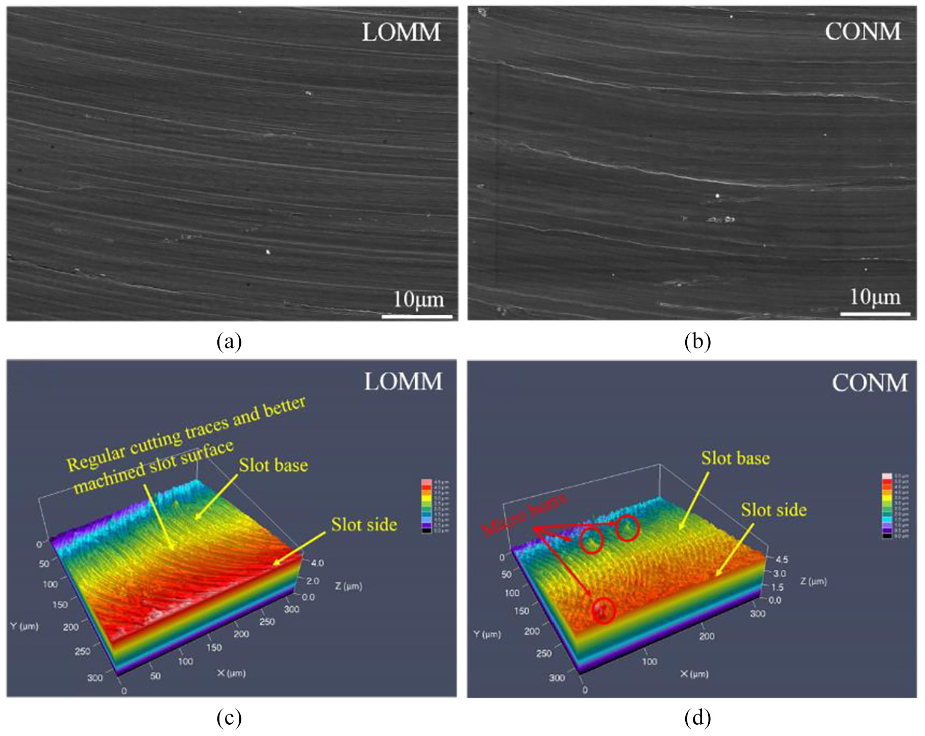
SEM images of the bottom of the machined slot from: (a) in LOMM and (b) in CONM, 3D surface morphology of the bottom of the machined slot from: (c) in LOMM and (d) in CONM, at ap= 3 μm and fz = 3 μm/z.
Tool wear
Relationships between tool wear and the variation of material removal amount in LOMM and CONM is shown in Figure 11, where three areas can be observed, namely, initial wear region, steady wear region, and severe wear region. It is observed that in the initial wear region, when the material removal amount reaches 0.12 mm3, the VBmax is 12 and 15.2 μm in LOMM and CONM, respectively. As the amount of material removal is increased, the maximum flank wear changes and continues to ascend. SEM images of the tool wear with different material removal amounts are presented in Figure 12. When the material removal amount increases in the ranges of 0.24–1.80 mm3 in LOMM, the wear state is in the steady region. It is mainly observed in Figure 12(a) that coating delamination occurs on the friction area between the workpiece and the flank face of the micro-tool. In the steady wear region of LOMM, slight coating delamination is induced by the friction between the tool and workpiece material due to the lower amount of material removal.
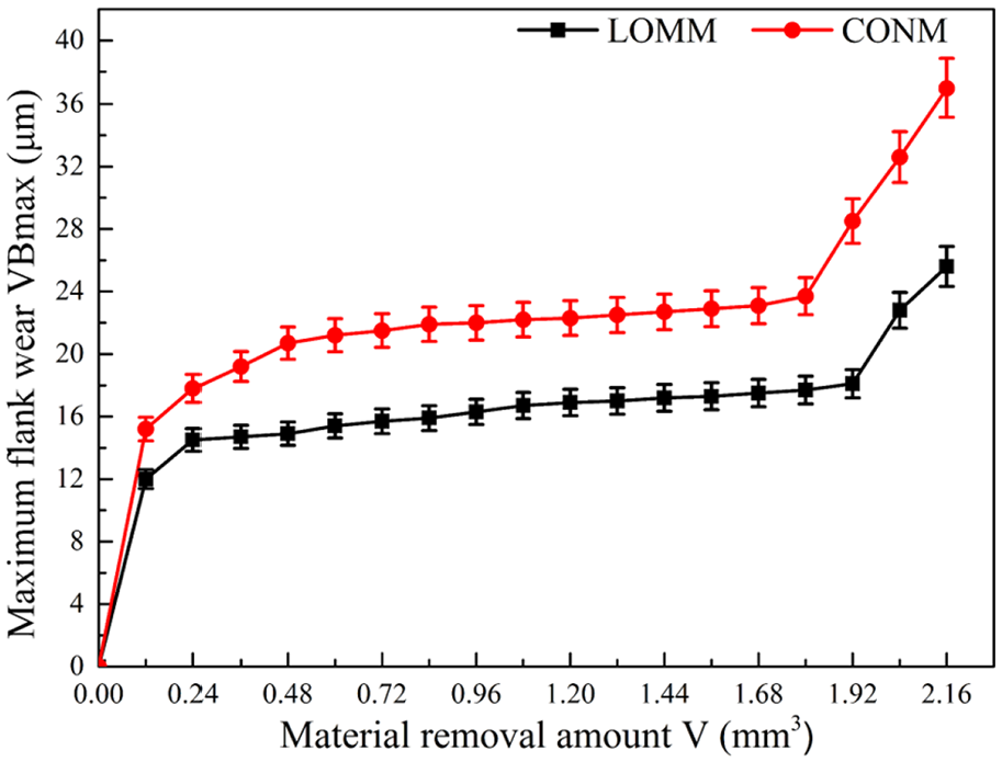
Maximum flank wear with the variation of material removal amount in LOMM and CONM at ap = 3 μm and fz = 3 μm/z.
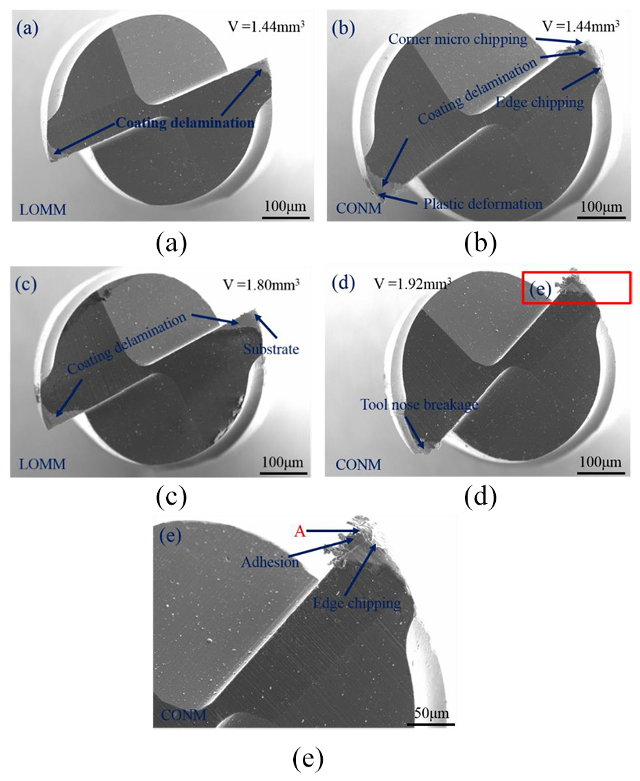
Surface morphology of tool wear after removing material volumes of: (a, b) 1.44 mm3 in LOMM and CONM, (c) 1.80 mm3 in LOMM, and (d, e) 1.92 mm3 in CONM.
In contrast, when the range of material removal amount is increased gradually from 0.48 to 1.80 mm3 in CONM, the tool wear is in the steady region. When the material removal amount reaches 1.44 mm3 in CONM, the tool wear mechanisms are chipping, coating delamination, and plastic deformation, as shown in Figure 12(b). Chipping of tool wear is found on the cutting-edge of the micro-end mill in micro-milling of plastic materials. 25 Chipping and plastic deformation are the types of micro-end mill wear mechanisms. In CONM, a higher cutting load leads to micro-chipping with the increment of material removal amount. In addition, chipping is caused due to high stresses and high temperature between workpiece surface and cutting-edge. 26 Furthermore, in the dry cutting process for micro-milling, the friction between micro-end mill and workpiece generates heat, resulting in thermal fluctuation at the tool cutting-edge. With continued increase in the MRR, the already chipped micro-end mill might experience flaking and produce even poorer surface finish. 27 The localized heat is attributed to chemical affinity of Inconel 718, resulting in plastic deformation.
In the catastrophic (severe or ultimate) wear region, the material removal amount in LOMM and CONM reaches 1.80 and 1.92 mm3, respectively. In LOMM, the tool wear mechanism is still coating delamination with the material removal amount increasing gradually to 1.80 mm3, as shown in Figure 12(c). The delamination area becomes large due to elevated temperature between a thin coating layer and workpiece material, which results in the exposure of the substrate of the micro-end mill. In addition, chipping of the tool nose and cutting-edge on the end mill do not occur in LOMM and the micro-end mill continues to machine the workpiece at V = 1.80 mm3. However, in CONM, plastic failure is observed when the flute or cutting-edge of the micro-end mill is chipped off catastrophically at V = 1.92 mm3, as presented in Figure 12(d). Plastic failure is attributed to the extreme heat generation at the tool nose contacting with the workpiece material during the dry micro-milling of Inconel 718. This softens the micro-tool and causes plastic deformation. Ultimately, the tool nose and cutting-edge lose their original geometry with the acceleration of the tool wear rate.
In addition, the adhesion is also produced because of friction since a substantial amount of heat is generated during the micro-milling process. Adhesion is classified under tool wear type, where a portion of workpiece materials attaches to the micro-end mill. EDS result reveals further quantitative analysis of point A in Figure 12(e) and the analyzed results are the same as that in Figure 6(a). Adhesion can be observed at the chipped cutting-edge, and some adhesion is seen and the adhesion wear is found to increase with the material removal amount increasing gradually. Thus, the micro-end mill might break with further micromachining, resulting in undesired surface finish.
Conclusion
A hybrid processing method involving LOMM is proposed. Under the laser-induced oxidation process, the material surface can generate a loose oxide layer and a relatively flat sublayer at optimal laser parameters of a scanning speed of 1 mm/s and an average laser power of 4.5 W. In addition, the thicknesses of the oxide layer and the sublayer are 24 and 18 μm, respectively.
In the comparative milling tests, the cutting force and the thrust force in LOMM are lower than those in CONM with the increase in the feed per tooth at the same depth of cut. The surface morphology in LOMM is better at ap = 3 μm and fz = 3 μm/z, which is superior to that of the other milling parameters. Under optimized milling parameters, the surface roughness and the top burr size on the up-milling side in LOMM reach 108.5 nm and 26.8 μm, respectively. In addition, the feed per tooth has a significant influence on the surface roughness, top burr size on both up-milling and down-milling sides, as well as surface morphology in LOMM and CONM.
In LOMM, the tool wear mechanism includes flank wear and coating delamination. In contrast, edge chipping, coating delamination, plastic deformation, and tool nose breakage are the dominant tool wear mechanisms in CONM. Compared to CONM, micro-tool life is improved and low cutting load is achieved in LOMM, which validates high efficiency in micromachining of Inconel 718 material.
Footnotes
Declaration of conflicting interests
The author(s) declared no potential conflicts of interest with respect to the research, authorship, and/or publication of this article.
Funding
The author(s) disclosed receipt of the following financial support for the research, authorship, and/or publication of this article: This work was supported by the National Natural Science Foundation of China (grant no. 51705249), the China Postdoctoral Science Foundation (grant no. 2019M661823), the Defense Industrial Technology Development Program (grant no. JCKY2018605C018), the Aeronautical Science Foundation of China (grant no. 2017ZE52047) and the Natural Science Foundation of Jiangsu Province (grant no. BK20160792).