
Abstract
Porous stainless steels, which have recently extended to the microscale domain, have been widely used for biomedical materials because they have good strength-to-weight ratio and superior corrosion resistance. Most components fabricated from porous materials still require secondary machining despite being produced in near-net shapes. However, they have poor machinability. High cutting force, high cutting temperature, poor surface integrity, and severe tool wear are encountered in the machining process of the difficult-to-cut porous materials. This article focuses on the micro-cutting performances and effects of cutting parameters in the micro-milling of porous stainless steel materials, including tool wear patterns and mechanism, effects of tool wear and cutting parameters on surface topography, cutting force, and cutting temperature. Comparative experiments were performed to investigate surface burr and cutting performances of porous materials in the micro-milling process. The effects of machining parameters on porous stainless steels in micro-milling are studied. Furthermore, a preliminary relationship of cutting parameters with micro-milling force and milling temperature is also established. The tool wear patterns and mechanisms were observed. Based on the findings, this article concluded that tool wear influences the surface morphology of the machined part and the effects of structural porosity on the cutting process during the micromachining of porous materials.
Introduction
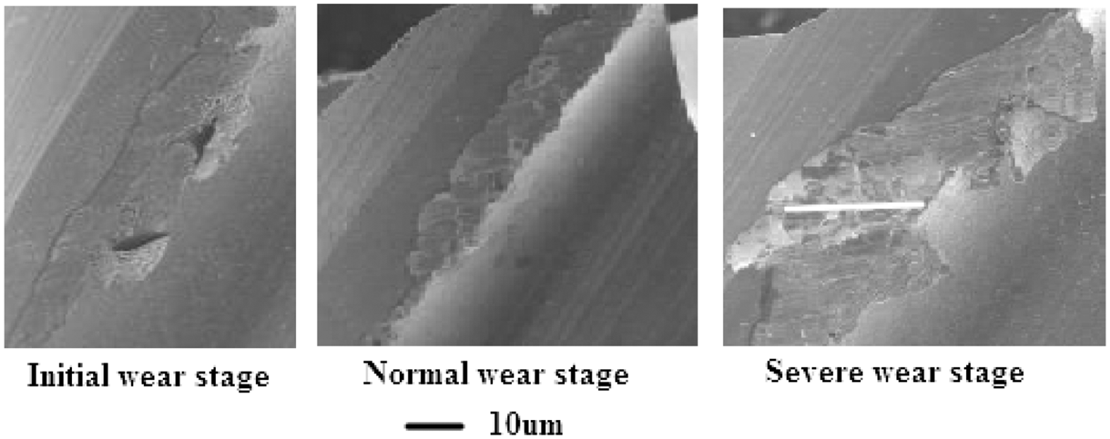
Porous metal materials have been widely used in aerospace, mechanical engineering, chemical engineering, environmental protection engineering, and biomedical engineering with the development of new materials.1–5 The mechanical properties of porous metal materials are influenced by microstructure characteristics.4–6 Porous materials can properly control pore diameter, direction, and distribution with their improvement and breakthrough in the manufacturing technology. However, the internal structure of porous materials is far more complex than this to meet the requirements in terms of pore size, porosity level, and material components. The hole connection with the external environment can be divided into three types: open hole, semi-open hole, and closed hole. However, the hole connection needs to be simplified or to take equivalent treatments in many cases of research because of the diversity and complexity of porous metal materials. The complex and irregular microstructure can be simplified to the regular and uniform model for analysis using the principle of homogenization. 7 The cross-sectional shapes of the holes include triangle, square, hexagon, circle, and ellipse shapes.6–8 The surface microstructure of porous stainless steel materials is shown in Figure 1. The internal microstructure of porous materials, including pore shape, pore diameter, and distribution rule, directly affects mechanical characteristics and machinability.
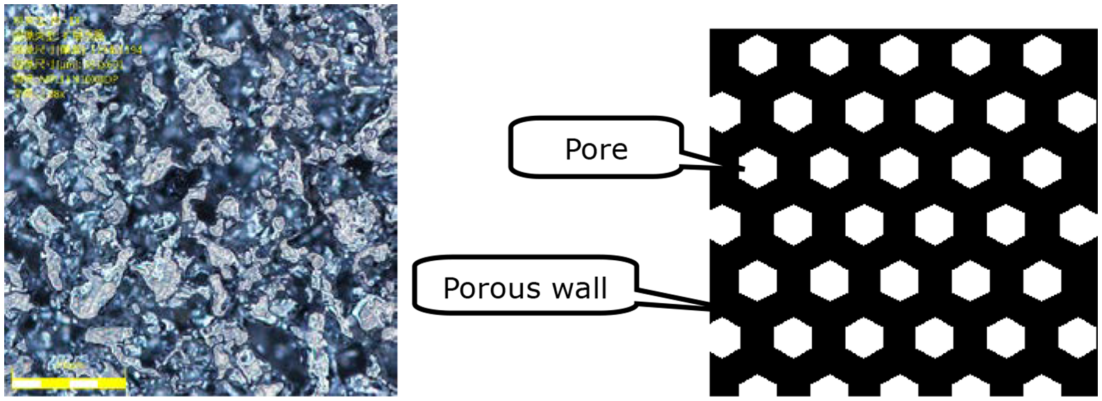
Surface microstructure of porous stainless steel material.
Several studies8,9 have been conducted on the machining mechanisms of the microstructure of porous materials. The complex microstructure of materials has great influence on machining quality and surface integrity. When macromachining porous materials, cutter wear was studied by Artamonov and Kononenko. 8 Tutunea-Fatan et al. 9 found that the effect of structural porosity on cutting forces experienced during micromachining is significant. Popov et al. 10 focused on finding the relationship between micro-milling performances and material microstructure effects. Furthermore, the non-conventional machining of porous materials was investigated to overcome difficulties in the conventional machining process.11,12
Titanium, ferrous alloys, and ceramic are used as the predominant porous materials in bone engineering and have received significant research attention.13–16 Jasperson et al. 13 compared micro-pin-fin and micromachining considering thermal–hydraulic performance and manufacturability. Shen and Brinson 14 studied the finite element modeling of porous titanium. Microstructure-level machining modeling of ferrous alloys was investigated by Chuzhoy. 15 Abolghasemi Fakhri et al. 16 used an image-based methodology to establish correlations between porosity and cutting force in micro-milling of porous titanium foams. Sharma et al. 17 presented an experimental work on wire electrical discharge machining process which identifies the influence of process parameters that affect the cutting rate, dimensional shift, and surface roughness while machining of porous nickel–titanium (Ni40Ti60) alloy.
Porous stainless steel is also widely used in biomedical applications because of its excellent performance of strength and creep resistance.18–20 The super mechanical properties are considered as a double-edged sword because porous stainless steels have poor machinability. Dewidar and Khalil 20 studied the processing and mechanical properties of porous 316L stainless steels for biomedical applications. However, the machinability and machining process of the porous stainless steel material have not been fully investigated, especially in the micro-cutting process.
With the characteristics of high production efficiency and low cost, the micro-cutting technology is particularly suitable for porous metal materials.9,10,16 Furthermore, in the micro-milling of porous materials, uneven stiffness distribution and poor machinability occur because of the anisotropy and non-continuity of the internal microstructure. The performances of cutting tools are closely related to surface quality. Moreover, the reasonable cutting parameters play a key role in the machining process. In the micromachining process, the feed per tooth and axial cut depth are extremely small, thereby inducing larger micro-milling force per unit and producing a high cutting temperature per unit.9,16 The machining parameters have a significant effect on cutting force, cutting temperature, cutting vibration, and surface quality.22,23 Fakhri et al. 24 revealed that the presence of a material discontinuity has a prevalent effect on cutting force variation in the case of micro-milling processes of porous titanium.
However, few studies have investigated tool wear and machined surface burr for porous metal materials in the high-speed micro-milling process. This study aims to evaluate the cutting performances according to the state-of-the-art machining process for porous stainless steels.
This article focuses on micro-cutting performances and effects of cutting parameters in the micro-milling of porous stainless steel materials, including tool wear patterns and mechanism, effects of tool wear and cutting parameters on surface topography, cutting force, and cutting temperature. In this article, the objective of study mainly includes workpiece quality, cutting tool wear, cutting force, and temperature. Tool wear in the micro-milling process of sintered porous stainless steel materials can make the cutting force change, thereby increasing the machining vibration and even causing chatter. This phenomenon seriously affects the stability of the micro-milling process. Thus, this article explores the indirect method and selection of cutting speed, axial cut depth, and feed rate, which are related to the cutting force, cutting vibration, and cutting temperatures.
Experimental setup and procedure
Workpiece and cutting tool
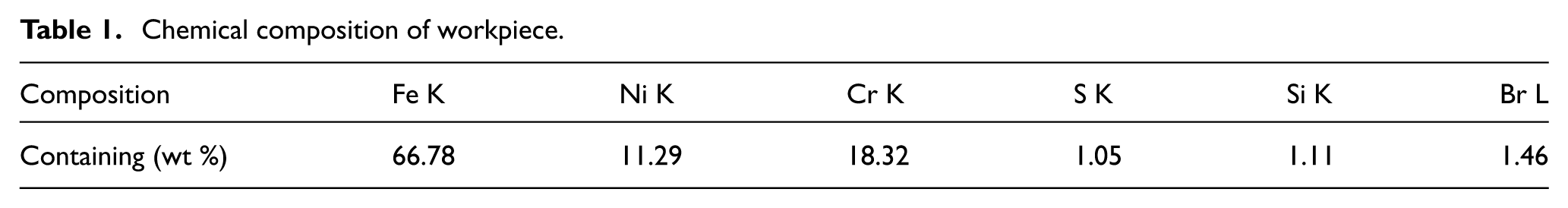
The material is porous stainless steel, as shown in Figures 2 and 3, and its chemical composition is reported in Table 1. The internal structure of porous materials is complex because it includes complex pore structures. The micro-milling cutting tool (with diameter of 0.8 mm) is a type of tungsten carbide cutting tool, as shown in Figure 4.
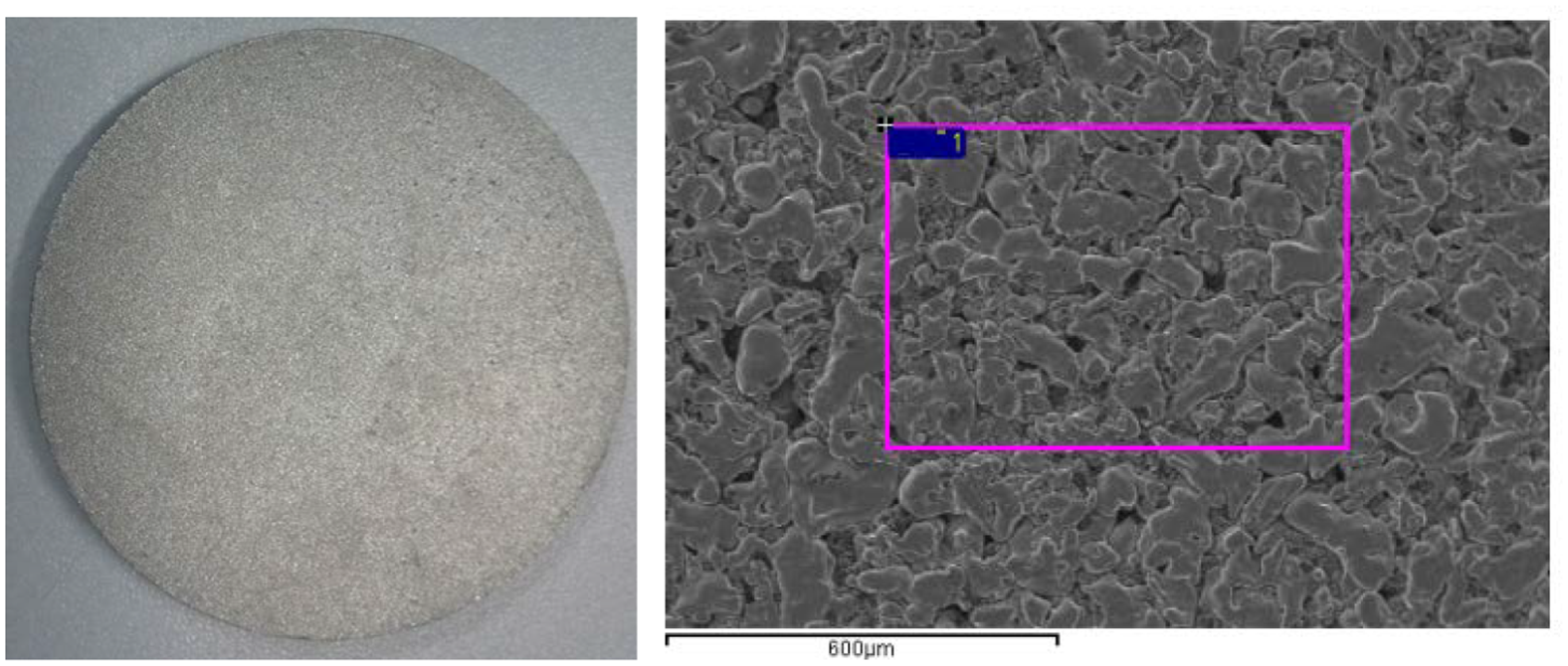
Microstructure of porous stainless steel workpiece.
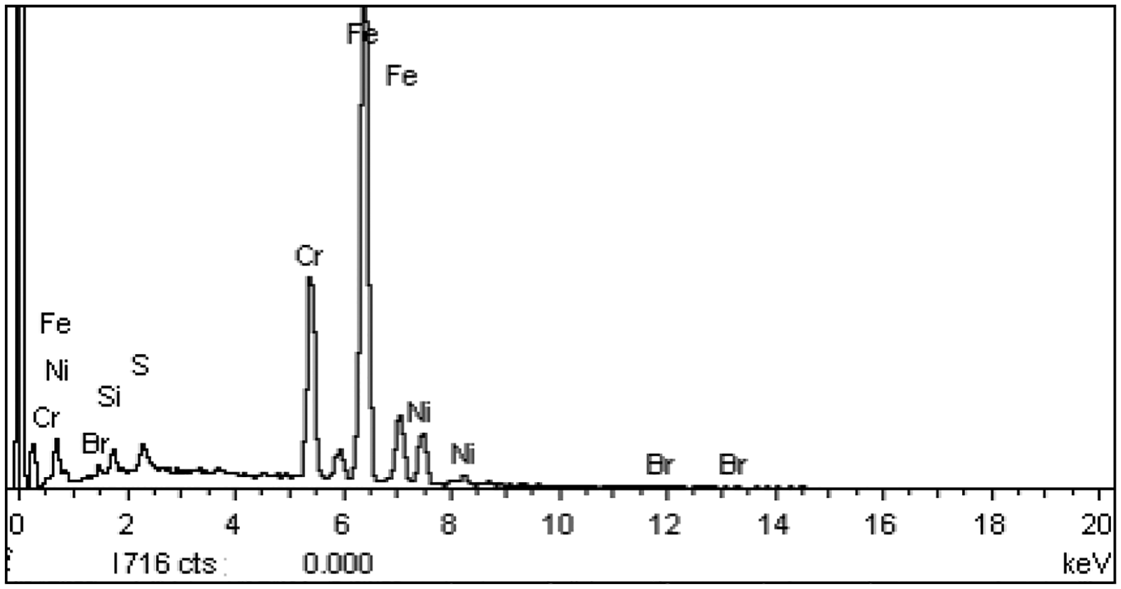
EDS of porous stainless steel workpiece.
Chemical composition of workpiece.
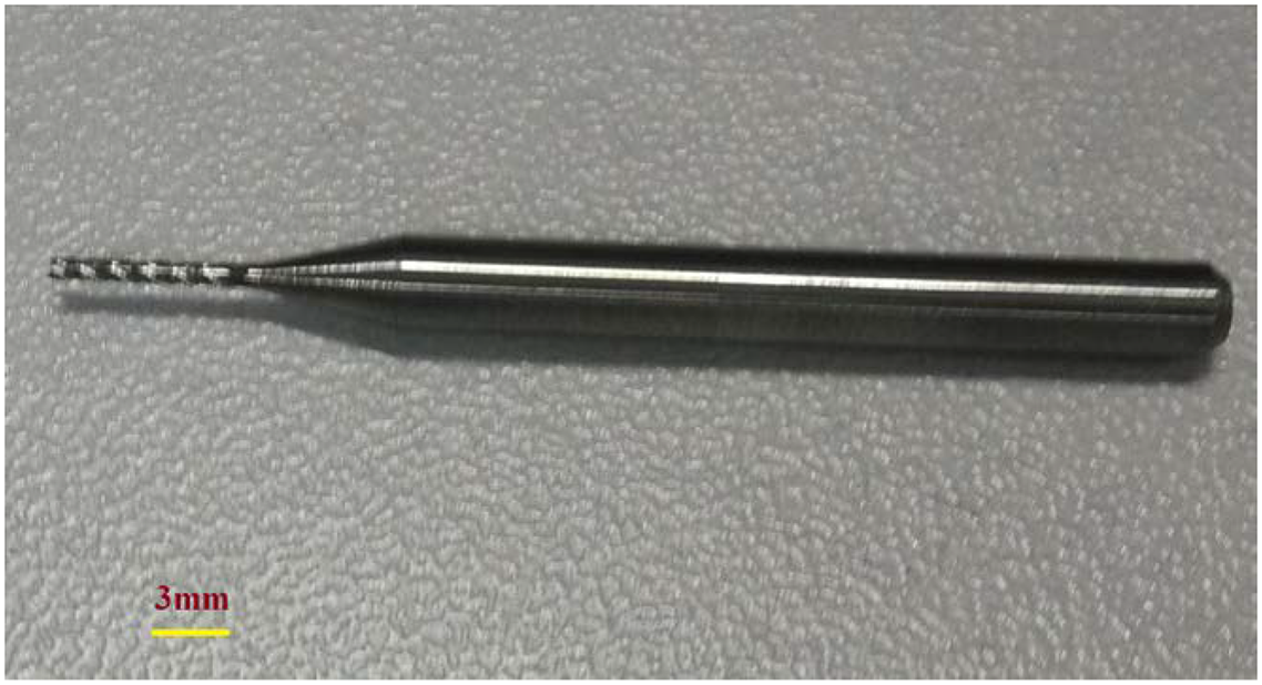
Micro-cutting tool.
Experimental procedure
An experiment was conducted using a three-axis micromachining experimental platform with a maximum motor speed of 80,000 r/min. The cutting tool wear condition monitoring schematic and the physical diagram of sintered porous materials micro-milling are shown in Figures 5 and 6, respectively.
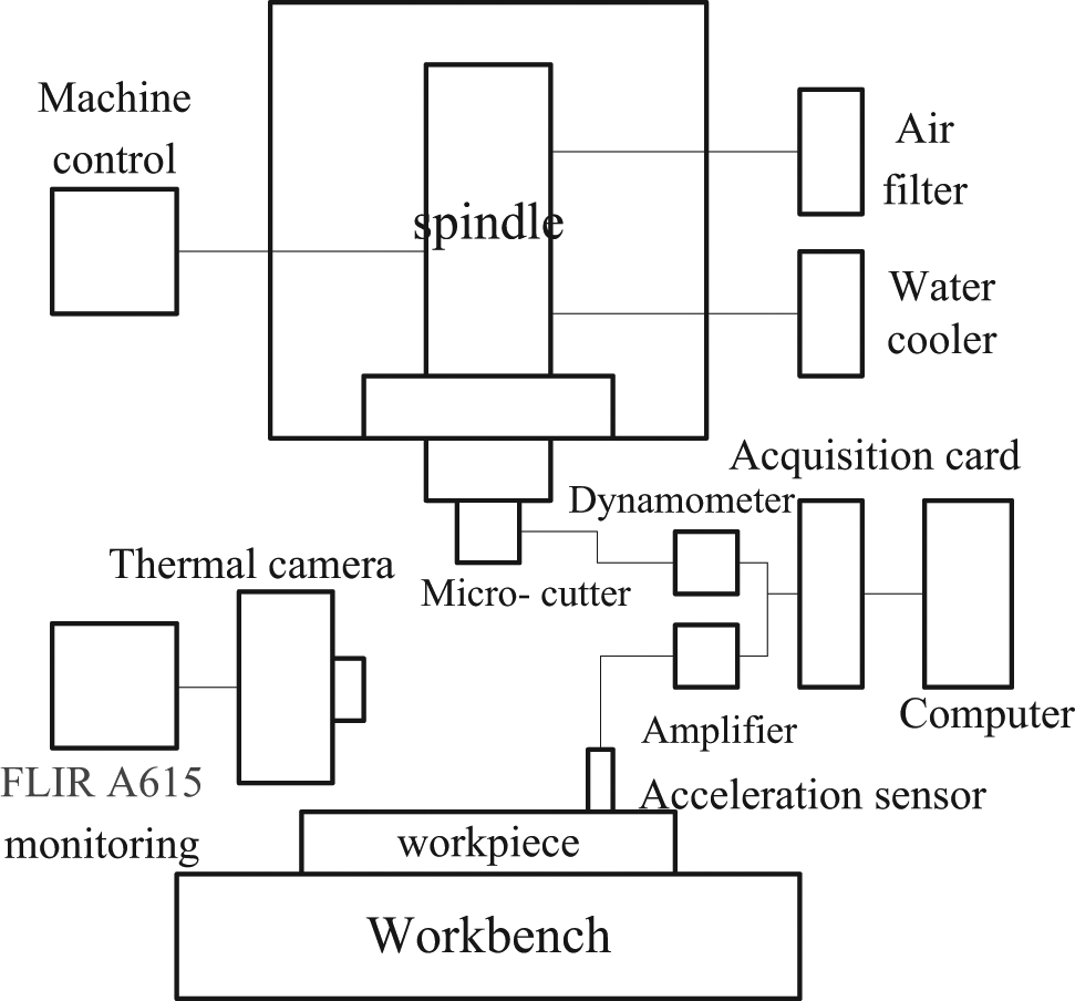
Schematic diagram of experiment.
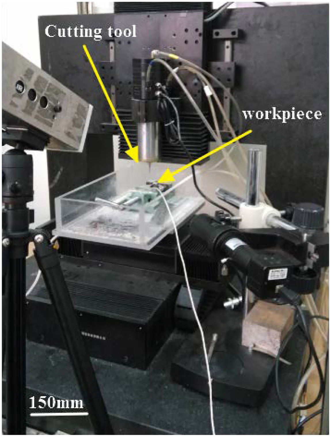
Online monitoring physical diagram of micro-cutting tool.
The experimental system mainly includes the micro-milling machine, precision dynamometer, acceleration sensor, amplifier, cutting force data acquisition and analysis system, and FLIR A615 thermal camera real-time monitoring system.
This experiment adopts the single-factor approach, as listed in Table 2, to study cutting speed, axial cut depth, and feed rate per tooth influence on cutting force, cutting temperature, and surface topography.
Cutting conditions.
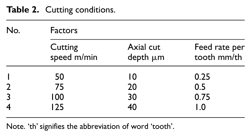
Note. ‘th’ signifies the abbreviation of word ‘tooth’
Results and discussions
Tool wear pattern and mechanism
Although the tool wear is a normal phenomenon, it directly affects the processing efficiency, surface quality, and processing costs. The tool wear is clearly worth considering in the field of machining of porous materials. 24 The concrete manifestation is as follows: reducing the machining precision, enlarging surface roughness, increasing cutting force and cutting temperature, and even causing vibration.
As mentioned, the diameter of the micro-cutting tool is 0.8 mm, while the diameter, stiffness, and strength are all relatively less and the cutting tool is often damaged in the use process. This section analyzes the tool wear morphology by scanning electron microscopy (SEM) and energy dispersive spectrometer (EDS) and then determines the wear types of the cutting tool. The SEM morphology analysis result of the micro-cutting tool is shown in Figure 7. A certain number of chips has been attached to the surface of the micro-cutting tool after micro-milling (Figure 7(a)). Moreover, the cutting tool has obvious micro-blade cracks, which are indicated by red circles in the partial enlargement diagram in Figure 7.
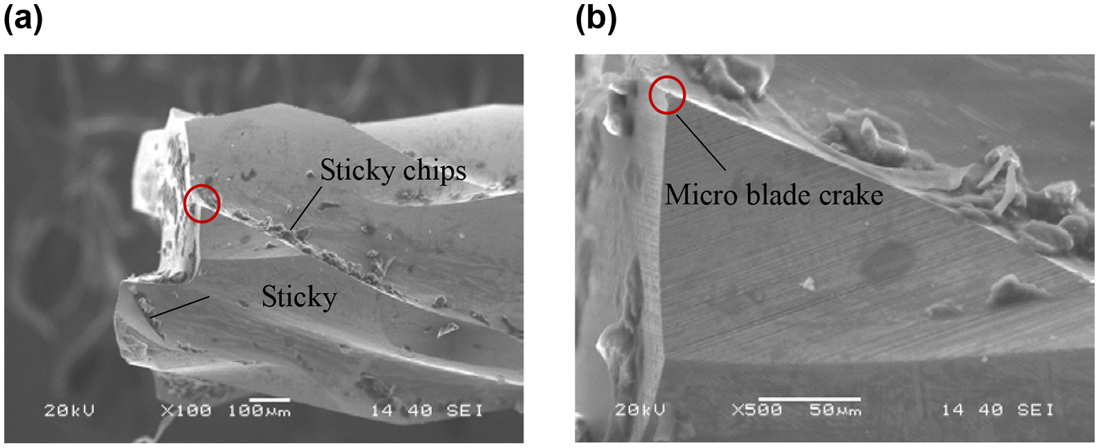
SEM morphology of the micro-milling cutting tool: (a) The sticky on the milling tool and (b) the micro-broken crack.
During the normal use process of the cutting tool, the typical tool wear morphology mainly includes rake face wear and boundary wear, which occur simultaneously, as well as flank wear and micro-blade cracks from the macro-graphic perspective. Judging from the dependence degree on temperature, the main causes of normal tool wear are mechanical, thermal, and chemical factors. The types of tool wear can be categorized into five, namely, abrasive, adhesion, diffusion, phase transition, and oxidation wear. EDS spectrum analysis is conducted on the cutting tools to determine the wear patterns of the micro-cutting tool.
The cutting tool wear area and non-wear area are shown in Figures 8 and 9. Metal composition and content have had noticeable variations in the cutting tool wear area. The tungsten carbide cutting tool is mostly composed of micropowders of high hardness and refractory metal carbides (WC, TiC), and the binders are cobalt (Co) and molybdenum (Mo). Therefore, C, Co, and W are the major elements, as shown in Figure 8. Some additional elements, such as Cr, O, Fe, and Ni, appear as shown by the comparison in Figures 8 and 9. Thus, we can determine the wear types of the cutting tool by analyzing these elements. The specific analysis is presented as follows.
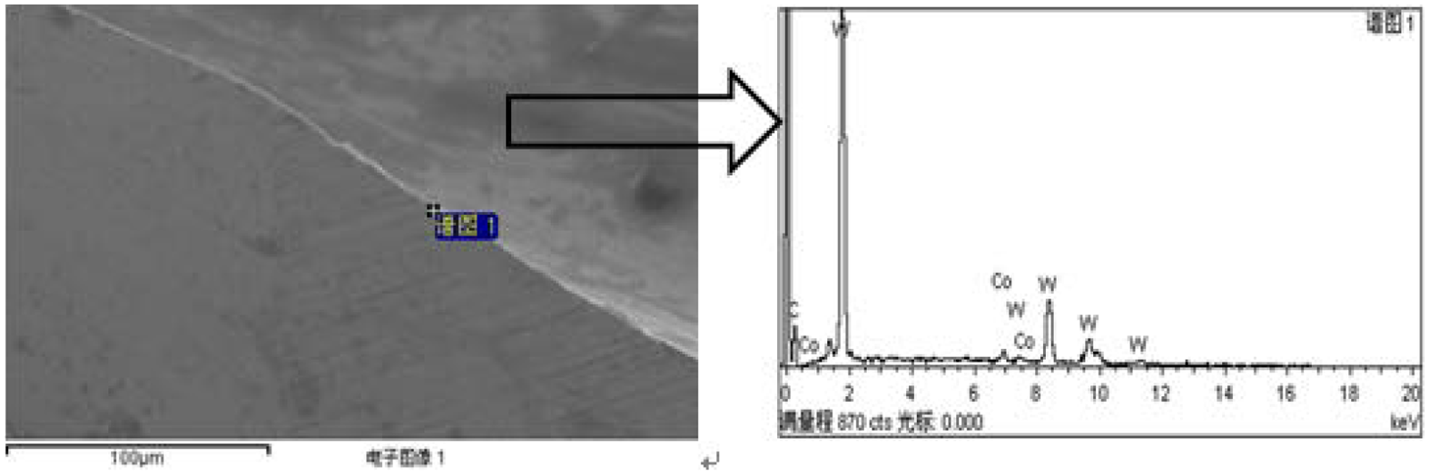
SEM and EDS analysis of non-wear zone of micro-milling cutting tool.
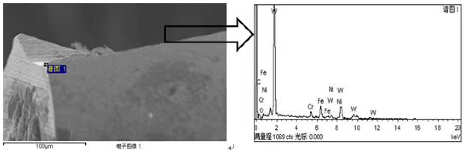
SEM and EDS analysis of wear zone of micro-milling cutting tool.
The main metal element of stainless steel workpiece is Cr, which also contains a small amount of Ni and N and indicates that the cutting tool has diffusion wear and adhesive wear. The appearance of O element mostly shows that the cutting tool has had an oxidation reaction with the oxygen in the air. Moreover, a certain amount of Fe in the EDS analysis diagram (Figure 9) may indicate that improper preservation of the cutting tool results in slight corrosion.
In summary, the cutting tool exhibits obvious micro-blade cracks and undergoes diffusion wear, adhesion wear, and oxidation wear during the use process. Therefore, excessive wear cutting tools should be replaced on time to ensure the accuracy and reliability of the micro-milling process.
Effect of tool wear and cutting parameters on surface topography
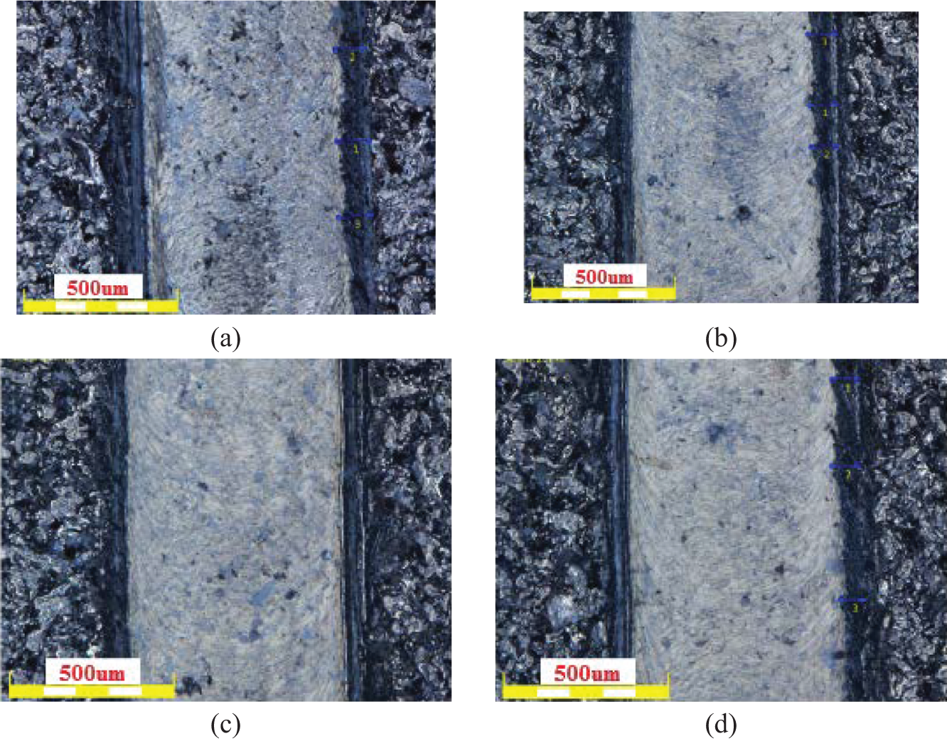
Under the axial cut depth of 20 µm and feed rate per tooth of 0.75 mm/s, the results can be obtained under the same magnification, as shown in Figure 10. Then, the influence of different cutting speeds on the surface quality of the machined workpiece is shown.
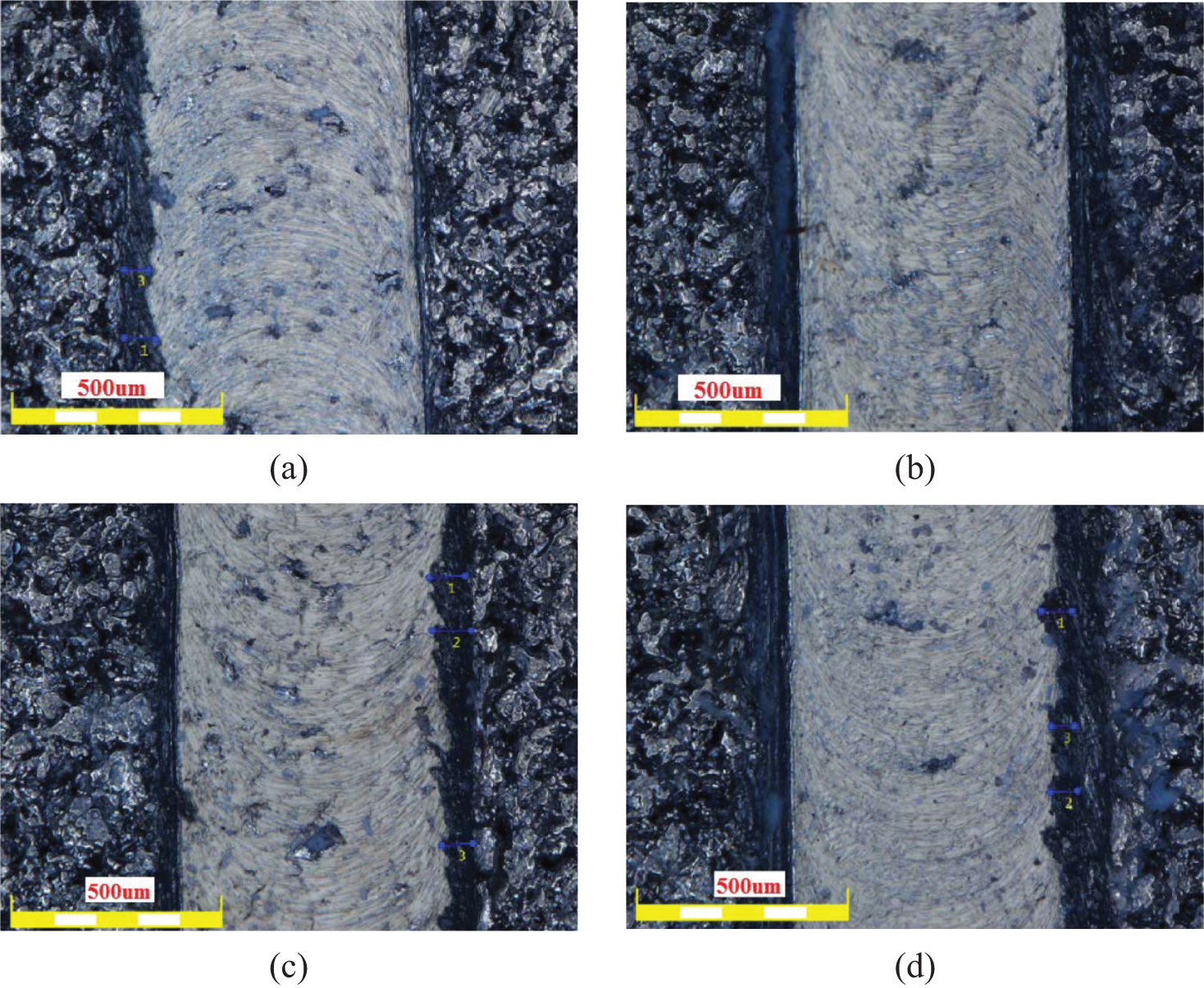
Micrographs of workpiece surface under different cutting speeds: (a) 50 m/min, (b) 75 m/min, (c) 100 m/min, and (d) 125 m/min.
As shown in Figure 10, neither the surface quality nor the burr phenomenon has obvious regularity with larger cutting speed. However, comparatively more burrs under low speed or high speed are produced, and burrs are at the minimum when the cutting speed is 75 m/min.
The vibration signals are directly conducted on the system dynamic process to sum up the effective details of cutting speeds and tool wear. The corresponding power spectrum results of the micro-cutting tool at different wear stages are obtained, as shown in Figure 11. The vibration signals show the vibration at different wear stages, as depicted in Figure 12.
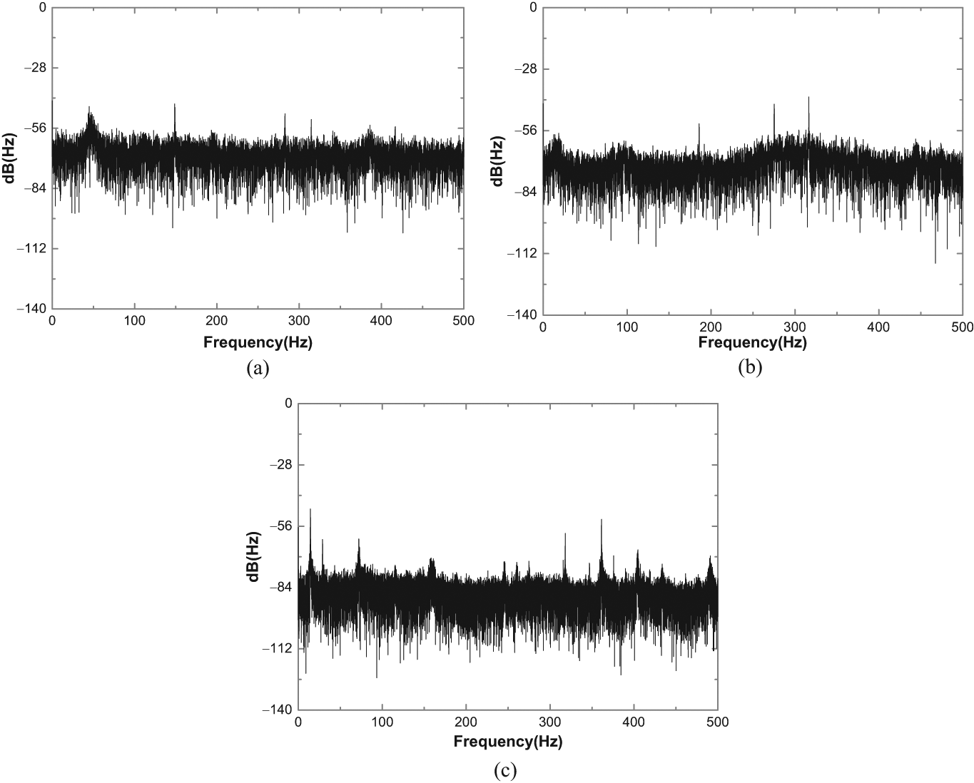
Power spectrum analysis of vibration signal: (a) initial wear stage (the average value is 68.35 dB), (b) normal wear stage (the average value is 72.13 dB), and (c) severe wear stage (the average value is 87.09 dB).
Wear of the cutting edge.
As shown in Figure 12, the amplitude of vibration signal gradually decreases as the micro-milling cutting tool wear level is aggravated. At the initial wear stage and the normal wear stage, the amplitudes of cutting vibration are from 56 to 84 dB. At the initial wear and the normal wear stage, the average value of amplitudes is 68.35 and 72.13 dB, respectively. However, the average value (87.10 dB) of the amplitudes at the severe wear stage is larger than the value at the normal wear stage due to a degree of instability.
As shown in Figures 11 and 12, vibration signals occur in the entire frequency range and in several frequency periods. Moreover, the energy of these vibration signals is higher when the micro-cutting tool wears more seriously. Based on this, tool wear has an important influence on the surface morphology of the machined part, and the effect of structural porosity on the cutting process during micromachining of porous materials is also identified.
Moreover, the influence of different feed rates per tooth, axial cut depth, and cutting speed on the surface quality of the machined workpiece is also determined.
In other words, every change in cutting speed, axial cut depth, and feed rate can influence the machined surface quality. However, strict rules are difficult to establish because the influence of every factor is not direct or absolute. Therefore, choosing milling parameters reasonably during the micro-milling process of porous materials should depend on the specific conditions and actual needs to guarantee better surface quality of parts.
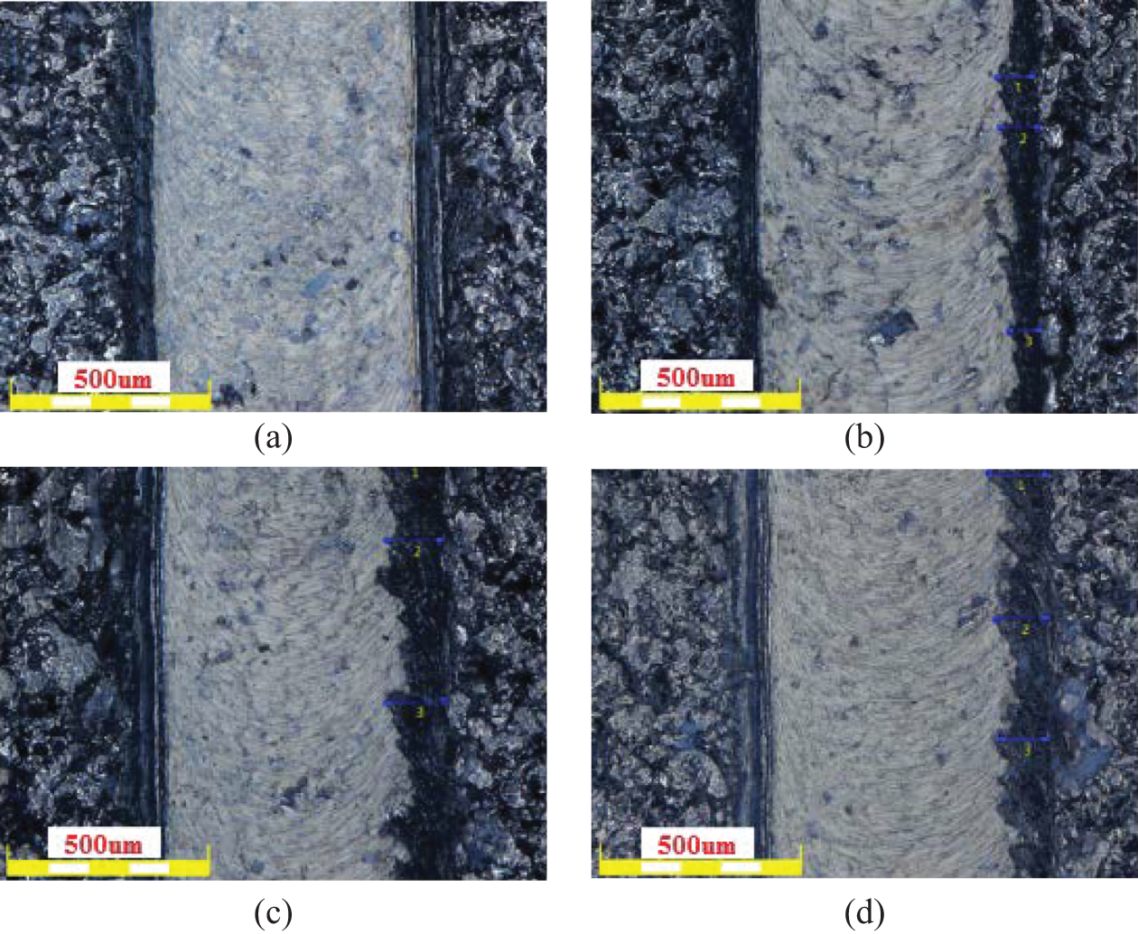
Figure 13 shows that the observed surface morphology slightly changes along with faster feed rate, but the burr phenomena are improved. In addition, burrs are rarely found at the machined surface edges under the third group of milling parameters, which means that the processing results are the best.
Micrographs of workpiece surface under different feed rates per tooth (cutting speed of 100 m/min and depth of cut (DOC) of 10 µm): (a) 0.25 mm/th, (b) 0.5 mm/th, (c) 0.75 mm/th, and (d) 1.0 mm/th.
Figure 14 shows more and longer burrs at the edges of the machined surface as the axial cut depth increases. That is, large axial cut depth can aggravate the burr phenomenon. Simultaneously, this condition means that increasing the axial cut depth may fail to improve the surface quality of the machined parts. However, combined with the above, the unreasonable parameters make the milling force large and the milling temperature high. Meanwhile, the larger instantaneous milling force induces vibration during the micro-milling process and then reduces the surface quality of the parts.
Micrographs of workpiece surface under different axial depths of cut (cutting speed of 100 m/min and feed rate per tooth of 0.75 mm/th): (a) 10 µm, (b) 20 µm, (c) 30 µm, and (d) 40 µm.
A comparison of Figures 10, 13, and 14 shows that a preliminary understanding is reached, that is, the surface quality of the workpiece has slight differences under different conditions of axial cut depth and cutting speed. In addition, regardless of how the feed rate per tooth, axial cut depth, and cutting speed change, the corresponding machined surface edge of every group of mill parameters displays the burr phenomenon at different degrees. Meanwhile, the burr phenomenon only occurs on one side of the surface because of the rotation direction of cutting. Moreover, comparison of the non-machined surface and machined surface shows that the pores on the non-machined surface are filled by chips from the milling processing, which can make ensure uniformity of the machined surface.
Effects of cutting parameters on micro-milling forces
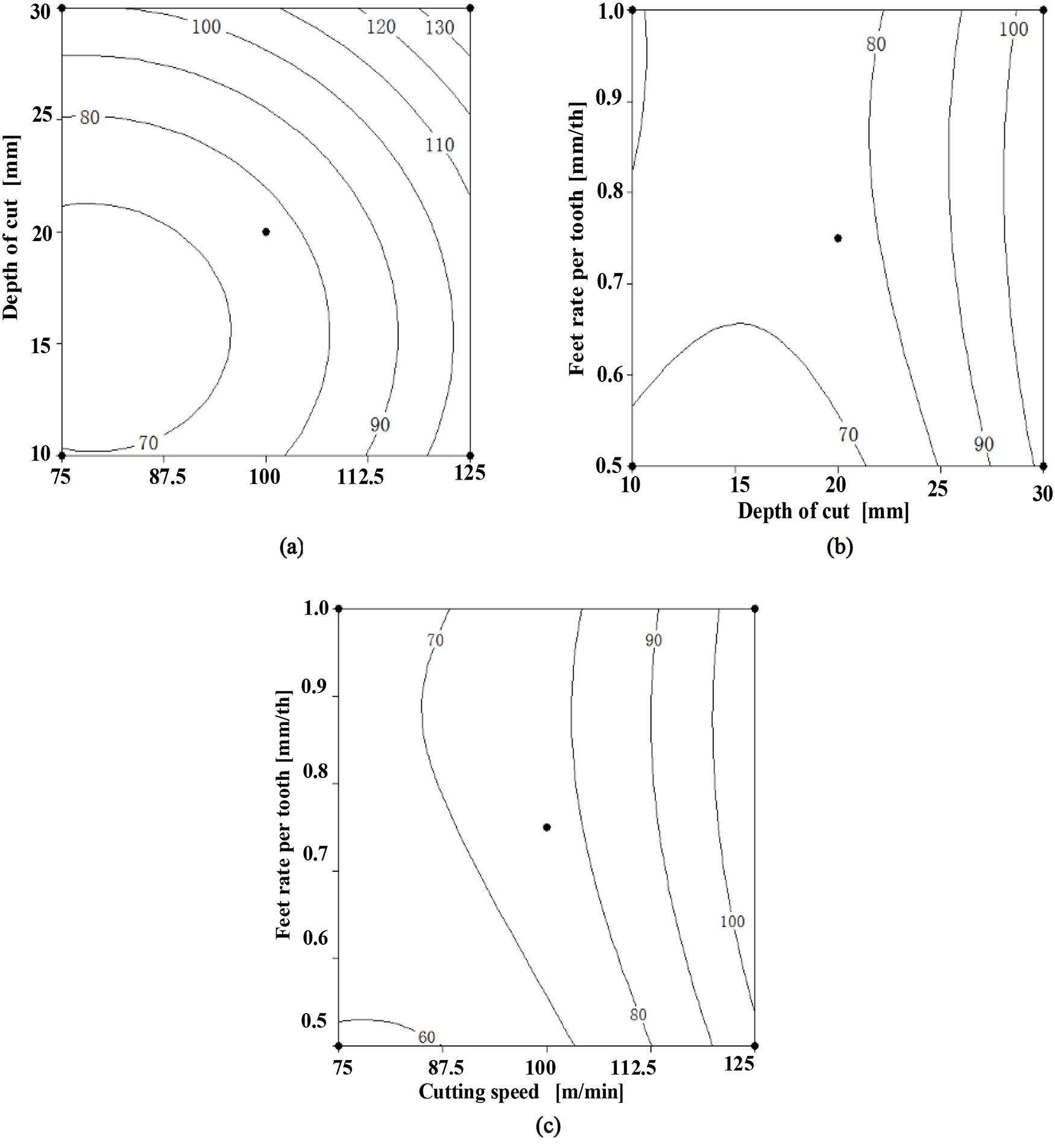
The micro-milling force combines significant information in this process, including that on machined surface quality, chatter, machining deformation, tool–chip friction, and tool wear. The micro-milling force is one of the most important performance parameters in the micro-milling process because it can obtain the resultant cutting forces, as shown in Figure 15.
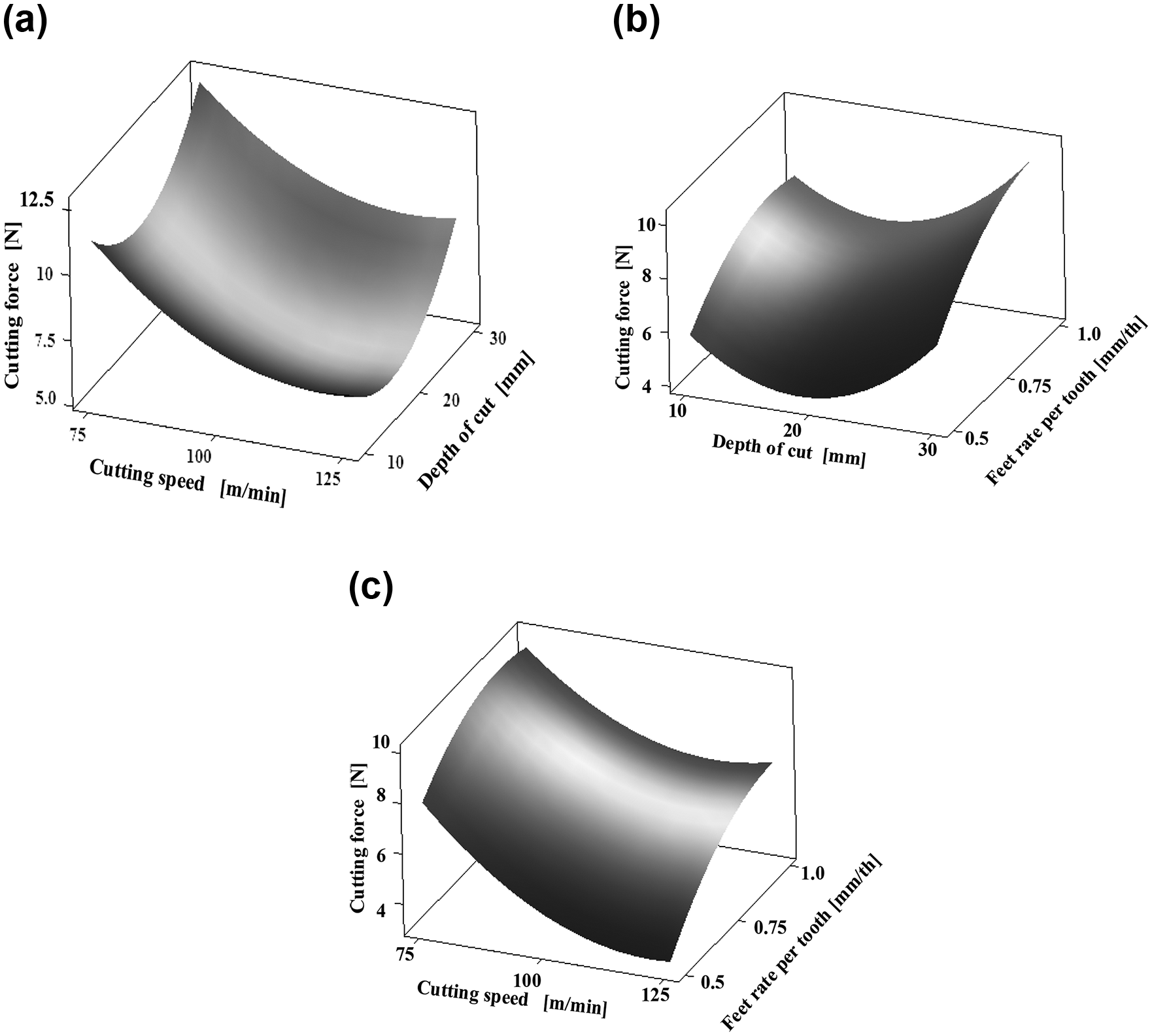
Effect of cutting parameters on resultant micro-milling force: (a) effects of cutting speed and depth of cut (DOC) on cutting force, (b) effects of depth of cut (DOC) and feed rate per tooth on cutting force, and (c) effects of cutting speed and feed rate per tooth on cutting force.
As indicated in Figure 15, micro-milling force F decreases as the cutting speed increases. When the cutting speed is constant, F decreases at first and then increases as the axial cut depth increases. The feed rate has the same influence as the axial cut depth on F. Furthermore, F appears as the peak value when the axial cut depth is 20 µm and the feed rate is 1.5 mm/s. Moreover, the forces have the opposite changes before and after this point.
Based on Figure 15, the cutting force F initially decreases and then increases gradually as the cutting speed accelerates or the axial cut depth increases; however, F increases gradually as the feed rate increases. The contour map of the cutting speed and axial cut depth is round, and their interaction effects with F are not significant. In addition, the contour maps in other cutting conditions show irregular shapes. It also indicated that their interactions are not obvious.
Effects of cutting parameters on milling temperatures
Milling temperatures can reflect variations in temperature between the cutting tool and workpiece along with the change in milling parameters. Another purpose is to adjust the cutting tool and observe the machining process through the thermal camera real-time monitoring system. The results are shown in Figure 16.
Effect of cutting parameters on milling temperatures: (a) effect of cutting speed and depth of cut (DOC), (b) effect of depth of cut (DOC) and feed rate, and (c) effect of cutting speed and feed rate.
Figure 16 indicates that the effects of cutting speed and axial cut depth on the milling temperature are the same; accelerating the cutting speed or increasing the axial cut depth can increase the milling temperature. As the feed rate gradually changes, the milling temperature similarly has a critical value when the feed rate is 1.5 mm/s, and its changing trend is exactly the opposite before and after this point.
Similarly, Figure 16 shows that the corresponding curve of the cutting speed and axial cut depth is steep, and accelerating the cutting speed or increasing the axial cut depth can increase the milling temperature. The feed rate curve is relatively smooth and the effects on the milling temperature are small. The contour map of the cutting speed and axial cut depth is round, which means that their interaction is not significant. Moreover, no regular contour map is available between the axial cut depth and feed rate and between the cutting speed and feed rate. Thus, their interaction is not obvious.
Conclusion and further works
This article introduces the micro-cutting performances and effects of cutting parameters in the micro-milling of porous stainless steel materials, including tool wear patterns and mechanism, effects of tool wear and cutting parameters on surface topography, cutting force, and cutting temperature, which are closely related to the tool life and surface quality of workpiece in machining of porous materials.
Main conclusion
Based on the experiment and analysis of the porous stainless steel micro-milling, the following conclusions are drawn from this investigation:
The cutting tool exhibits obvious micro-blade cracks and diffusion wear, adhesion wear, and oxidation wear during the use process. Observing the cutting tool wear state online and replacing the excessive wear cutting tools on time are essential for reducing the cutting tool damage and ensuring the performance of the parts.
The influence of cutting speed, axial cut depth, and feed rate on the surface morphology of the machined parts is neither direct nor absolute. Therefore, choosing reasonable milling parameters should depend on the specific conditions and actual needs to guarantee good surface quality of parts during the micro-milling process of porous materials.
The cutting force initially decreases and then increases gradually as the cutting speed accelerates or the axial cut depth increases. However, the cutting force increases gradually as the feed rate increases. Accelerating the cutting speed or increasing axial cut depth can increase the milling temperature. The effects of feed rate on the milling temperature are small. The interaction between the cutting speed and axial cut depth is not significant. Moreover, no regular contour map is available. The interactions between axial cut depth and feed rate and between cutting speed and feed rate are not obvious.
Further research
It should be noted that this study has only tested constant cutting tools without tool coating and lubrication. Therefore, it is a limitation of this investigation due to cutting performances have coupling effects with lubrication and tool coating. Additionally, more topics are worth considering. Two of them are of the most interest and need to be further investigated in future. The first one is to test the effects of near dry cutting conditions (e.g. using minimum quantity lubrication). The second one is to study how to match cutting parameters with different types or porosities of porous materials, and so on. This will help select optimal process parameters in the potential industry application.
Footnotes
Declaration of conflicting interests
The author(s) declared no potential conflicts of interest with respect to the research, authorship, and/or publication of this article.
Funding
The author(s) disclosed receipt of the following financial support for the research, authorship, and/or publication of this article: This work was supported by the National Natural Science Foundation of China (No. 51305174).