
Abstract
Surface roughness is an important parameter that determines the post-manufacturing product quality. In this study, effect of cutting parameters, coating material and the built-up edge phenomenon on the surface roughness were investigated in micro end milling process of Inconel 718 using a white light interferometer and scanning electron microscopy. A micro end mill with a diameter of 768 µm coated with five separate coating materials (AlTiN, AlCrN, TiAlN + AlCrN, TiAlN + WC/C and diamond-like carbon) was used in this study. According to the results obtained, mean surface roughness values of surfaces machined with a diamond-like carbon-coated and AlTiN-coated cutting tool were lower than for other coatings. However, surface roughness values of surfaces obtained with tools coated with TiAlN + AlCrN and AlCrN were higher. Specifically, the formation of built-up edge causes chips to be smeared on machined surfaces, which has a negative impact on the surface quality. As can be expected, wear occurs faster on uncoated tools. As a result of this, the edge radius may increase excessively, and the mean surface roughness value may decrease. Also in this study, multivariate analysis of variance was carried out and the parameter that was most effective on surface roughness was established.
Introduction
Manufacturing of industrial products in miniature sizes is a popular engineering research topic. Research conducted within this context is focused on micro-engineering, which also includes miniature product manufacturing and micro-manufacturing processes.1–5 This research topic targets the determination of systematics of micro-products and their manufacturing systems, ranging from the development of micro-product designs to modeling, manufacturing and assembly6–10 In a study carried out in this scope, Cardoso and Davim 11 analyzed manufacturing strategies and cutting parameters and established optimal surface roughness and appropriate conditions for processing time.
Surface roughness plays an important role in establishing the quality of parts that are manufactured and in the optimization of manufacturing conditions.12,13 Tool wear, properties of the material being machined, the vibration and sensitivity of the machine tool and adhesion of chips on the edges of the cutting tool (built-up edge (BUE)) are parameters affecting roughness.14–17 In micro milling, the size of the cutting process and differences in chip removal mechanisms make roughness more important. Besides, an additional surface refinement process is usually not possible following manufacturing due to machined geometries having a small structure.
One of the important elements determining surface quality in the micro milling process is the minimum chip thickness. The effect of this parameter on the machined surface characteristics has been clearly put forth in previous studies.12,18–21 It was suggested that the roughness value increased in chip thickness under minimum chip thicknesses and in feeds per flute values.9,21–24 In a study conducted on the issue, experimental results from a roughness model developed depending on minimum chip thickness showed that a rougher surface was obtained in parameters under minimum chip thickness. 12 These results were also supported by a study conducted by Vogler et al. 21 Filiz et al. 25 noted that the machining mode in the form of ploughing in micro milling had an impact on roughness. In addition, wear occurring on the cutting tool was also noted to affect surface roughness. Run out of the cutting tool is mentioned as playing an effective role in obtaining a low surface quality.26–28 In a previous study, it was demonstrated that a rougher surface was obtained due to run out and the cause of this situation is shown to be nonhomogeneous cutting marks. 26 Another important parameter on surface roughness is the workpiece’s material properties. Elastic deformation occurring during the machining of ductile materials was noted to cause an increase in roughness. However, brittle materials were suggested to provide smoother surfaces.22,24,29
In the processing of nickel alloys, the characteristics of the machined surfaces are basically determined by failures such as residual stress found under the surface, deformation hardening and BUE formation, cracks and tearing observed on the surface due to tool wear. 30 However, in micro milling, studies conducted to investigate the performance of coated tools on surface roughness are quite limited. Studies on the micro machinability of material to be hard machined, especially Inconel 718, are almost nonexistent. In a recent study, 31 tool wear and coating performance in micro milling of Inconel 718 material were investigated. In a study by Arunachalama et al., 32 the performance of tools coated with TiN, TiCN, CrN, CrTiAlN and TiAlN in micro milling of H13 tool steel was investigated. According to the results obtained, it was suggested that CrN coating provided a good surface quality at first, but a rougher surface was obtained due to wear.
This study evaluates the performance of tools coated with AlTiN, AlCrN, TiAlN + AlCrN, TiAlN + WC/C and diamond-like carbon (DLC) and WC-Co uncoated tools in the micro milling of Inconel 718 nickel alloy in terms of the quality of the machined surface. In addition, the way in which the characteristics of the coatings affected the surface roughness was also investigated. However, the effect of wear occurring during the cutting process on surface quality was studied as well. Evaluations were conducted with three-dimensional (3D) analysis of machined surfaces. Moreover, the parameters affecting surface roughness and their levels were established by means of variance analysis.
Materials and methods
In this study, Inconel 718 nickel-based super alloy, which is used in important fields of industry (aviation and aeronautics, medical industry and so on) and is attracting interest with its superior mechanical properties, was chosen as the workpiece. The workpiece has dimensions of 40 × 30 × 10 mm. For cutting experiments, an ultrafine grained carbide tool with 768 µm diameter having a K10–K20 quality and micro end mills coated with different compositions (TiAlN + AlCrN, DLC, AlTiN, TiAlN + WC/C and AlCrN) were used as cutting tools. Some of the characteristic properties of the coatings are given in Table 1. For cutting parameters, 20,000 r/min, a constant angular velocity (Vc = 48 m/min) and 1.25, 2.5, 3.75 and 5 µm/flute feed rates and 0.1, 0.15 and 0.2 mm depths of cut values were used. During all the cutting experiments, a constant cutting length (Lc) of 120 mm was considered. Surface roughness values were measured on cutting zone at the beginning of cutting process for each tool. Additionally, surface measurements were carried out for cutting length of 120 mm in order to see the effect of wear on surface roughness for AlCrN-coated tool. Experiments were carried out under dry cutting conditions at multiprocess MicroTools-DT 110 miniature machine tool (Figure 1). The machine tool has a high-speed spindle motor (60,000 r/min) and also has a positioning accuracy of ±1 µm for each axis. Values of roughness that occurred on surfaces were measured with a ZYGO Newview 7200 white light interferometer.
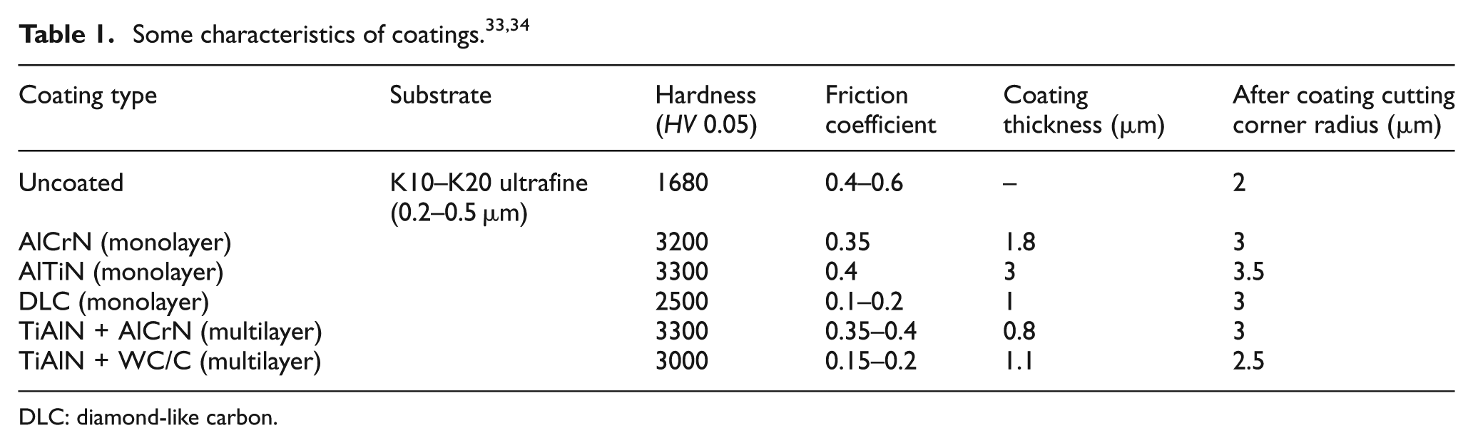
DLC: diamond-like carbon.
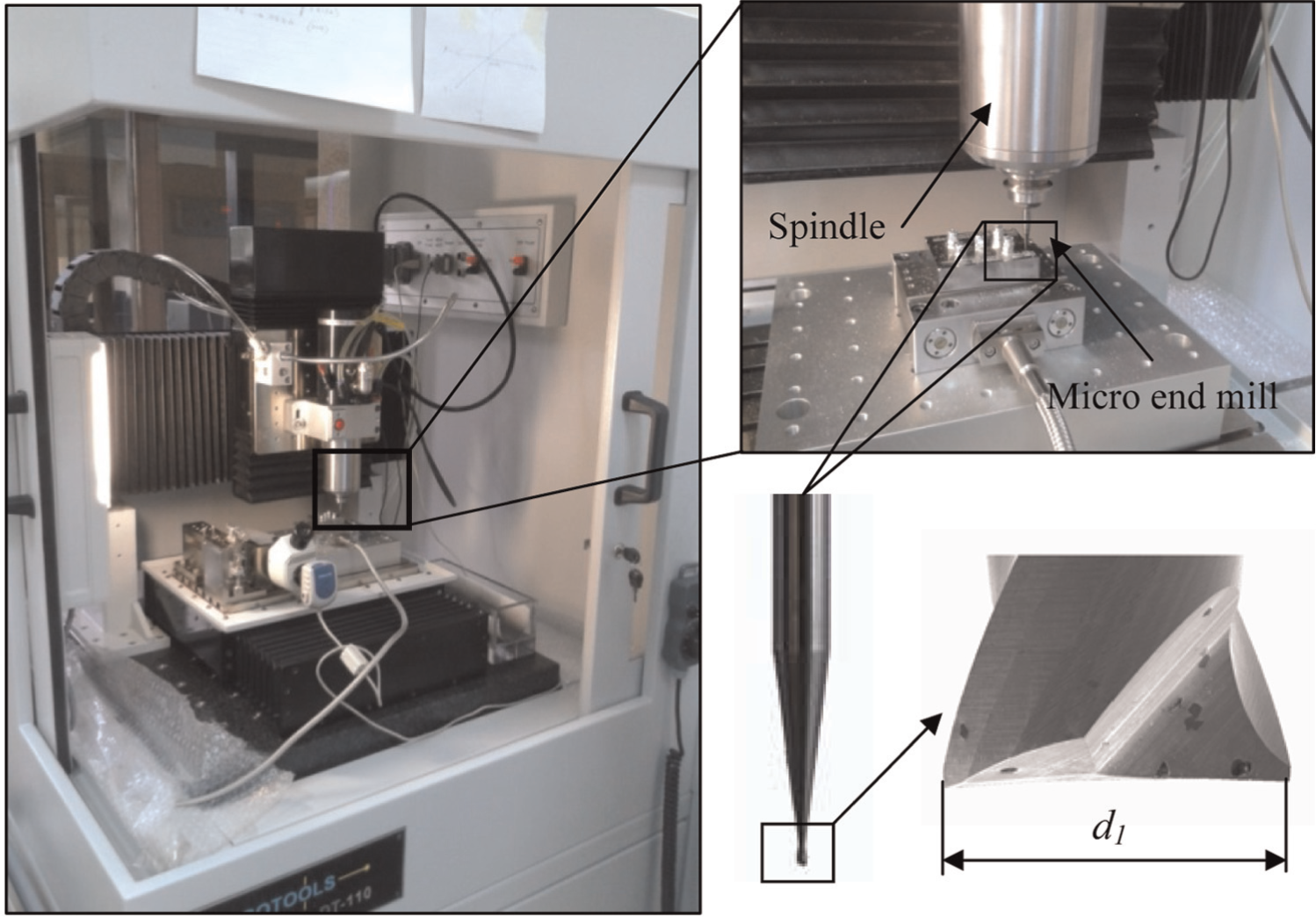
Testing apparatus used in the study.
In addition to the experimental study, variance analysis was carried out to establish the parameters affecting the surface roughness that occurs during the cutting process. Three main design factors were determined for this analysis. These are as follows: tool type (A), feed rate (B) and depth of cut (C). Six different tools for tool type factor (A), four different feed rates for feed rate factor (B) and three different depths of cut for depth of cut factor (C) are taken into consideration as levels. The factors used in the design and their levels are given in Table 2. For the later stages of this study, the factors will be expressed by letter definitions and levels by such definitions as L1, L2,…, L6.
Design parameters and levels.
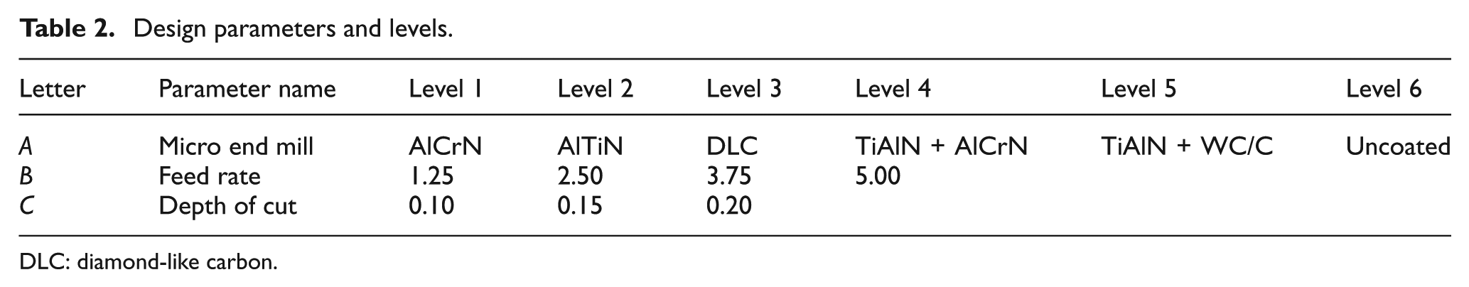
DLC: diamond-like carbon.
In this study, multivariate analysis of variance (MANOVA) has been used to identify the statistical significance of the parameters using Minitab software. MANOVA is a statistical test procedure for comparing multivariate (population) means of several groups. Unlike analysis of variance (ANOVA), it uses the variance–covariance between variables in testing the statistical significance of the mean differences. It is a generalized form of ANOVA. It is used when there are two or more dependent variables. 35 Multivariate statistical analysis is concerned with analyzing and understanding data in high dimensions. 36 In multivariate analysis, the most frequently used test procedures are often invariant with respect to a group of transformations, leaving the testing problems invariant. In such situations, an application of group theory results leads us in a straightforward way to the desired test procedures. Most of the commonly used test criteria in multivariate analysis are invariant test procedures with respect to a certain group of transformations, leaving the problem in question invariant. 37 A multivariate statistic refers to an assortment of descriptive and inferential techniques that have been developed to handle situations in which sets of variables are involved either as predictors or as measures of performance. 38 The F-test is based on a comparison of the sum of squares under the full and the reduced models. The degrees of freedom are calculated as the number of observations minus the number of parameters. 36
Results and discussion
Evaluation of surface roughness
In the metal cutting process, surface roughness basically varies depending on feed rate, cutting edge radius and cutting tool entering angle.13,39 Beyond this approach that is theoretically suggested, actual surface roughness is significantly affected by tool wear at the time of manufacturing, the properties of the machined material, vibrations and the sensitivity of the machine tool. However, the BUE formation that occurs by chips sticking to the cutting tool edge has a negative impact on surface roughness.14–16
Surface roughness changes obtained for each tool depending on feed rates are given in Figure 2(a). When graphs are examined, the surface machined with the DLC-coated tool has the minimum roughness value, followed by the AlTiN- and TiAlN + WC/C-coated cutting tools. Surface roughness values obtained with uncoated cutting tool were observed to be close to those of AlTiN- and TiAlN + WC/C-coated cutting tools. There may be several reasons for such a difference between coated cutting tools. One of these is the propensity of tools to BUE formation because studies suggest that the BUE formation on the cutting tool increases surface roughness.32,40 DLC and TiAlN + WC/C coatings do not have a chemical interaction with the workpiece specifically due to the lubricating effect of the C element found in their composition. Besides, the lower friction coefficients of these coatings cause relatively lower heat formation. When BUE formation is generally considered in medium cutting temperatures, the friction coefficient may be thought to contribute to BUE formation. However, it is known from the studies that CrN phase found in the compositions of TiAlN + AlCrN- and AlCrN-coated cutting tools for which the maximum roughness values are observed has a propensity to chemical interaction with Inconel 718 super alloy. 41 However, the friction coefficients of TiAlN + AlCrN and AlCrN coatings being higher than for other coating types explain the results observed in the roughness values. However, the roughness value of the surface machined with the AlTiN-coated tool having the same friction coefficient as the TiAlN + AlCrN and AlCrN coatings is lower. It was suggested in a study that AlTiN coating had a weak chemical interaction with Inconel 718 super alloy. 42 Another study was carried out with CrN- and TiN-coated tools and found that surfaces machined with CrN coating were rougher. 43 In the light of this information, the differences in the surface roughness performance of the AlTiN and AlCrN coatings are caused by the CrN and TiN phases. Therefore, it was understood from the study that the differences observed between the roughness values of AlTiN and TiAlN + AlCrN with AlCrN-coated tools were natural.
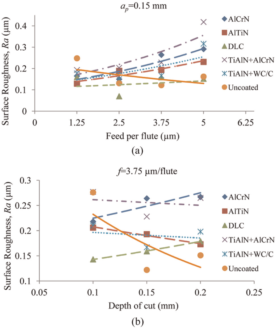
Change in the roughness value depending on feed rates, depth of cut and type of coating.
Another important parameter on surface roughness is the cutting edge radius. From Table 1, the cutting tool edge radius values, the radius values (3 µm) of DLC-, TiAlN + AlCrN- and AlCrN-coated tools prove to be the same. In addition, a 1-µm difference was observed between the edge radius of the TiAlN + WC/C-coated tool (2.5 µm) and the AlTiN-coated tool (3.5 µm). This may also explain the fact that the roughness values of the AlTiN-coated cutting tool with a higher friction coefficient and the TiAlN + WC/C-coated cutting tool are close since the relatively high edge radius of the AlTiN-coated cutting tool is believed to cause an improvement in the obtained roughness value. As is known, a better roughness value is obtained by an increasing edge radius. 22 However, it is possible to note that a generally indecisive situation occurs with uncoated cutting tools in general. The edge radius of uncoated tool is smaller than that of coated tool. Consequently, the machined surface is expected to be rough due to smaller edge radius. However, on the contrary, a less rough surface was obtained. The reason for this can be shown that the uncoated tool will suddenly wear due to strength of workpiece and the tool edge radius will increase depending on wear. As is known, the edge radii increase with wear.25,44,45 A higher radius value on the cutting tool edge provides a better roughness value. 22 Another result obtained from the graph is the increase in the roughness value with the rise in feed per flute. Basically, two parameters become prominent in the theoretical approach used for the estimation of surface roughness (Ri = f2/32 × r). These are feed rate and cutting tool edge radius. 39 In this analytical expression, an increase in the feed rate causes a rise in the roughness value; however, a growth in the edge radius leads to a decrease in the roughness value. Changes in surface roughness depending on the depth of cut are given in Figure 2(b). The graph reveals an inconsistent situation in general, meaning that it is difficult to note an increasing or decreasing effect of changes in the depth of cut on roughness. This obtained outcome was observed to be parallel with approaches suggested in the literature. Also in such studies, an obvious effect of depth of cut on roughness is not mentioned.21,46,47
In order to put forth clearly the effect of BUE formation on the obtained surface roughness, scanning electron microscope (SEM) analyses were carried out on the tools (Figure 3). When the SEM images were analyzed, it was observed that the workpiece materials intensively adhere especially on the cutting edges of the TiAlN + AlCrN, AlCrN-coated and uncoated (WC-Co) tools. In addition, in the DLC-, TiAlN + WC/C- and AlTiN-coated tools, there was less BUE formation. These results obtained from SEM images confirm the previously mentioned approach. The chip particles that adhere on the cutting edges of tools change the friction conditions between the cutting tool and workpiece during the cutting process. Chips in between the tool and workpiece adhere and even smear on the surface of the workpiece due to the effect of friction and temperature that occurs during the cutting process. Thus, the quality of the surface is negatively affected.
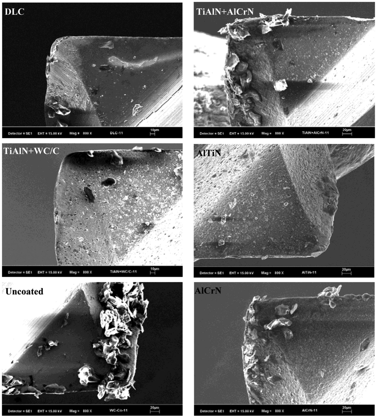
SEM images of chips adhering on the cutting edges of each tool.
When the 3D topographic images of the machined surfaces are analyzed, the chip particles adhering on the surface of the workpiece due to BUE formation can be clearly observed (Figure 4). It is estimated that the workpiece particles adhering on the surface are transferred to the surface by means of the cutting edge. The chip particles on the machined surfaces were mostly observed on the surfaces machined with the AlCrN, TiAlN + AlCrN and uncoated tools. These results also confirm the SEM images of the cutting edges in Figure 3. Chips adhering on the tool squeeze between the workpiece and tool during the cutting process. Under these newly formed conditions, the adhering chips and the workpiece are interacting. As a result, some of the chip particles on the cutting edge adhere to the workpiece surface. Some studies also suggest that chips adhere on the workpiece surface depending on BUE formation in the cutting process of Inconel 718 nickel alloy.32,40,48 Besides, chip adhesion was observed to be less on surfaces machined with DLC-, AlTiN- and TiAlN + WC/C-coated tools. As a result, it is possible to conclude that the chip adhesion that occurs on machined surfaces is directly related with the resistance of tools to BUE formation.
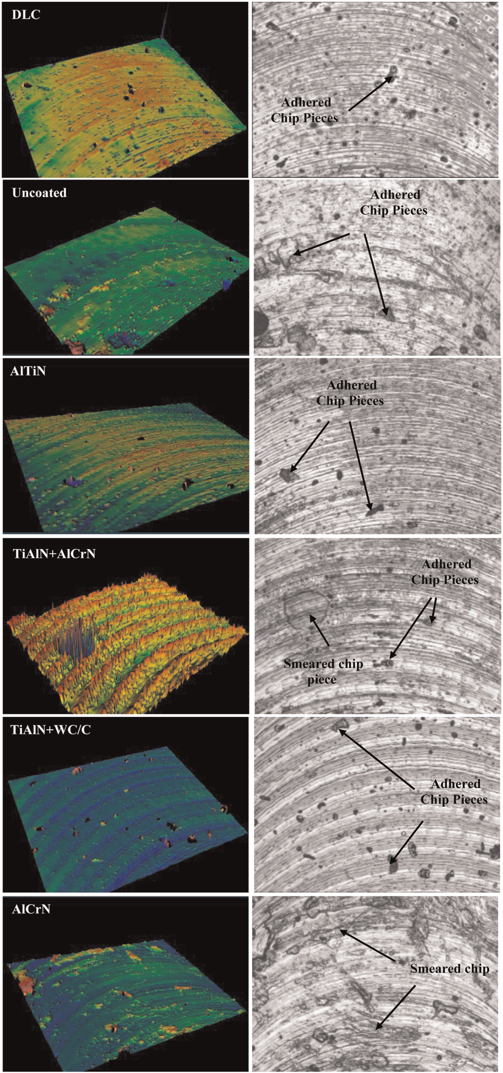
Three-dimensional topographic images of surfaces machined at 2.5 µm/flute feed rate and 0.15 mm depth of cut.
Deformations occurring on the surface of the workpiece due to BUE were also confirmed with SEM analysis. Images of the surface machined with the AlCrN-coated cutting tool given in Figure 5 provide important clues to the fact that surfaces deteriorate due to a BUE event. Chip adhesion on the cutting edge significantly reduces the chip removal capability of the tool. Thus, a plastic deformation occurs on the workpiece surface in contact with the tool with the effect of excessive friction and stresses in a direction parallel to the surface. Deformation marks observed on the surface are believed to be a result of the cutting edge of the tool losing sharpness with the effect of BUE. The loss of sharpness causes the occurrence of bigger cutting forces in both radial and axial directions during cutting. Therefore, with the passing of the tool, the surface becomes deformed by rubbing due to the friction between the tool and the workpiece and the stresses also occurring. 49 This will also cause an increase in the residual stress under the surface. 30 Such an effect of BUE formation on the machined surface is also noted in studies in the literature.40,50 One study suggests that deformations occur in the form of creeping on surfaces in contact with the tool during chip removal, and that residual stresses form below such areas. Plastic deformations were noted to occur in such areas due to the residual stresses. 50 Also, the SEM image in Figure 5(b) clearly demonstrates that the cutting tool deformed the workpiece by rubbing, and the slip lines that occurred as a result show how the cutting tool interacted with the surface.
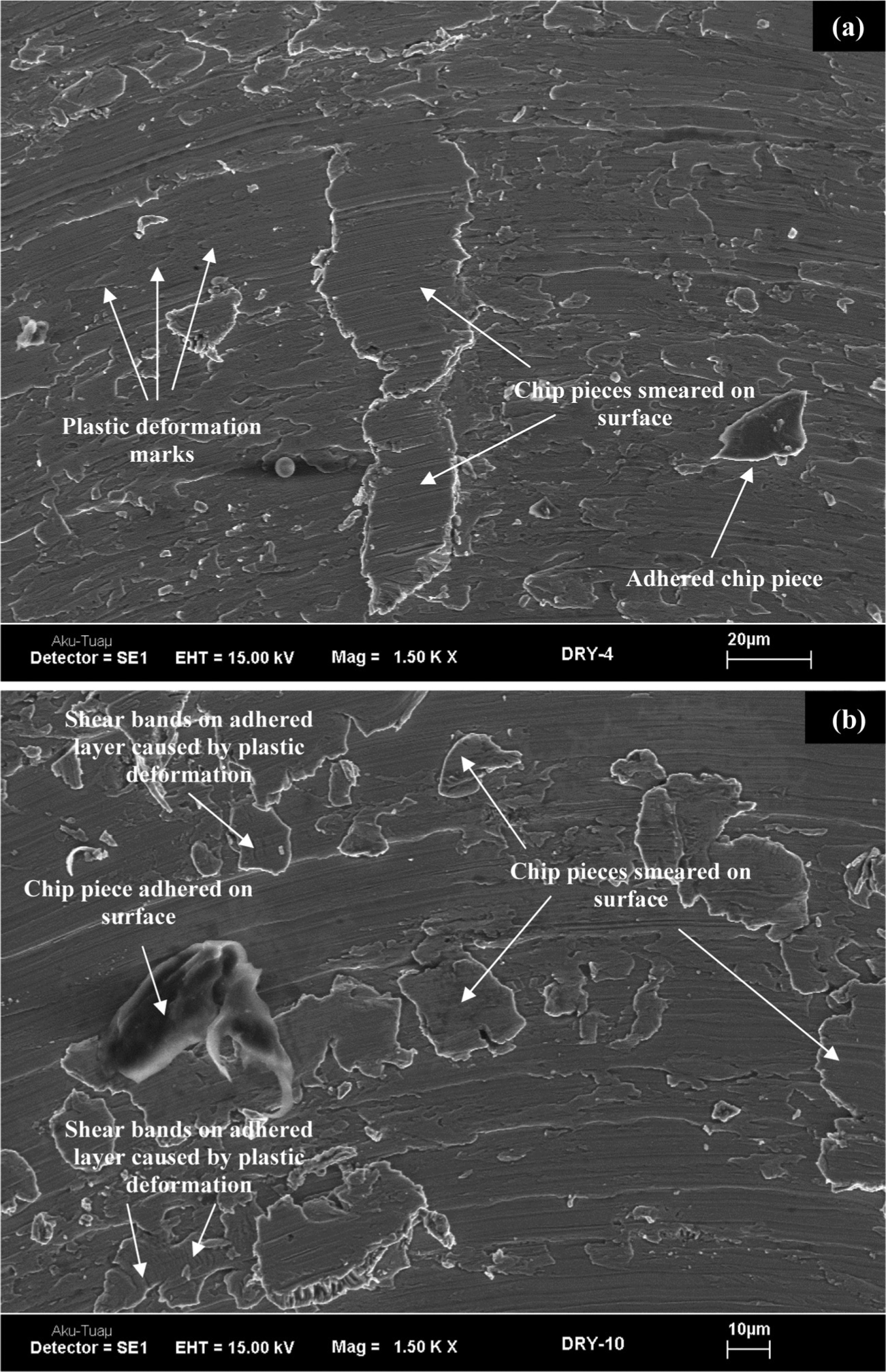
SEM images of the surface machined with AlCrN-coated cutting tool at 2.5 µm/flute feeding and 0.15 mm depth of cut: (a) 0–5 mm and (b) 40–45 mm.
Establishing active parameters with variance analysis
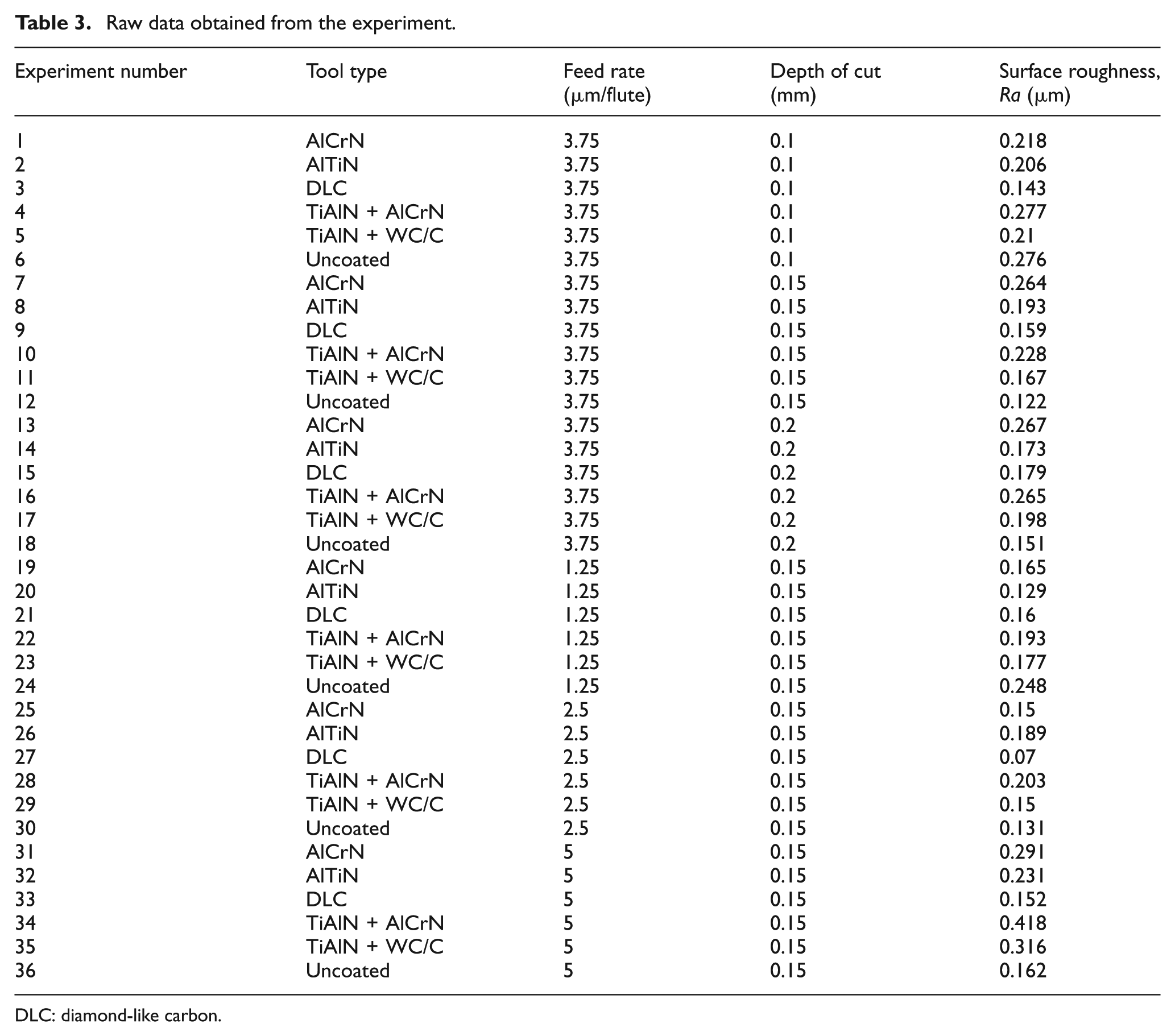
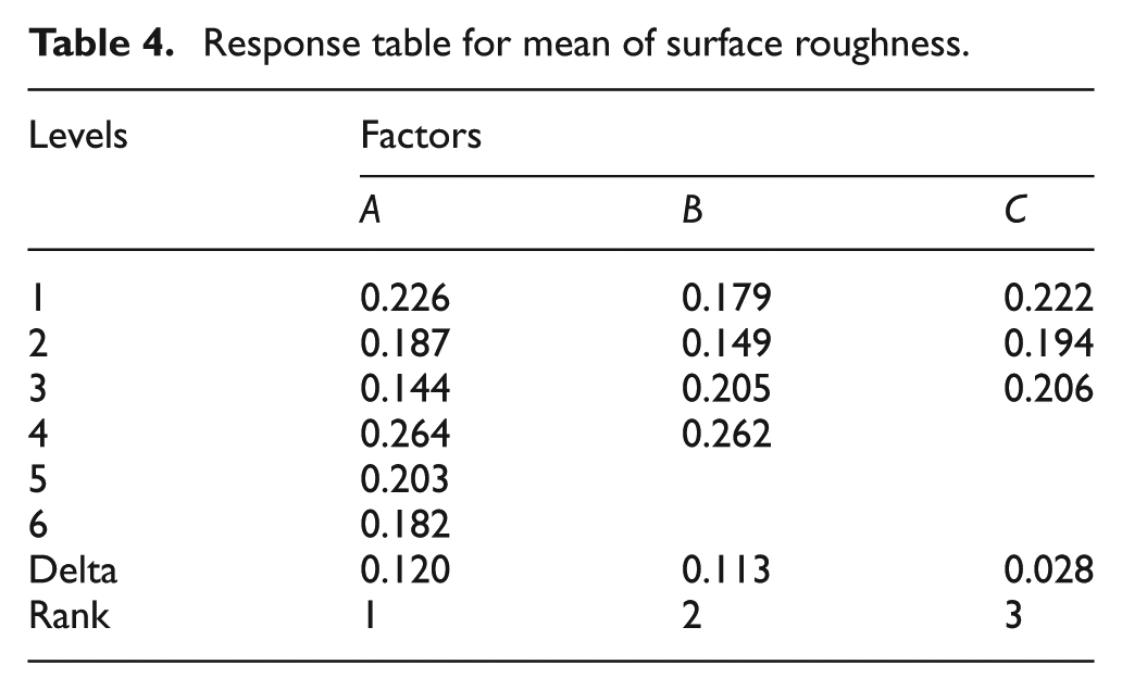
Within the scope of the study, statistical analyses of experimental data given in Table 3 were carried out in order to establish the active parameter on surface roughness. Thus, it was possible to establish which parameter was most significant in the obtained roughness values. Within this scope, the response table (Table 4) contains a row for the average surface roughness for each factor level, delta and rank. Delta is the difference between the maximum and minimum average surface roughness for the factor. The rank is the rank of each delta, where rank 1 is the largest delta. 35 According to Table 4, the factor A (micro end mills) is the most effective factor, followed by feed rate (B) and depth of cut (C). Variance analysis is shown in Table 5 according to mean surface roughness. The responses based on average (Table 4) and the variance analysis results (Table 5) demonstrate a parallelism. The A factor has the highest delta value based on Table 4 (cutting tool), but the effectiveness of the A factor is observed to come second according to the variance analysis table. The effectiveness of the B factor (feed rate) according to the delta value in the response table comes second, but the effectiveness of this factor comes first according to the variance analysis table. The F values of both factors are quite high and their confidence rates are 0.995. The C factor (depth of cut) produces similar results in both the response table and the variance table. According to this, it may be noted that the levels defined for the C factor do not have a marked effect on surface roughness. This is confirmed by the low F value, a confidence level of 0.496 and a delta value of 0.028. It may be concluded that the most important factors to take into consideration in this experiment based on variance analysis are feed rate (B), micro end mills (A) and depth of cut (C).
Raw data obtained from the experiment.
DLC: diamond-like carbon.
Response table for mean of surface roughness.
Analysis of variance for average surface roughness.
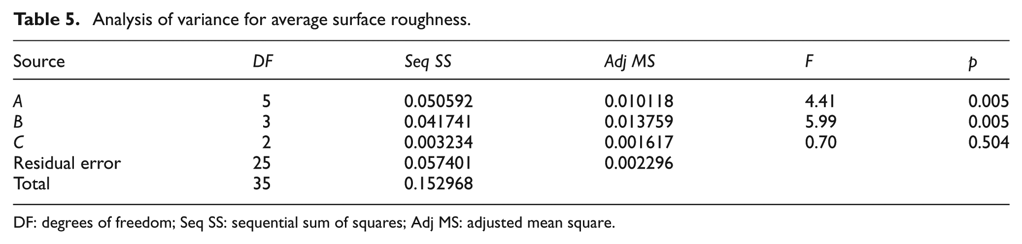
DF: degrees of freedom; Seq SS: sequential sum of squares; Adj MS: adjusted mean square.
The effect of average surface roughness values in the lower levels of each factor is given in Figure 6. In order to obtain the lowest surface roughness here, the effects of each parameter on the result are as follows: while the third level (DLC) of the cutting tool factor (A) provided the lowest surface roughness value, its fourth level (TiAlN + AlCrN) produced the highest value. While the second level (2.50 µm/flute) of feed rate factor (B) gave the lowest value, its fourth level (5.0 µm/flute) produced the highest value. Finally, the second level (0.15 mm) of the depth of cut factor (C) provided the lowest value, but its first level (0.1 mm) produced the highest value. According to this graph, the active levels of the factors are A3, B2 and C2, respectively. The surface roughness values obtained by the levels and values of these factors are given in Table 6, and the lowest surface roughness value was obtained.
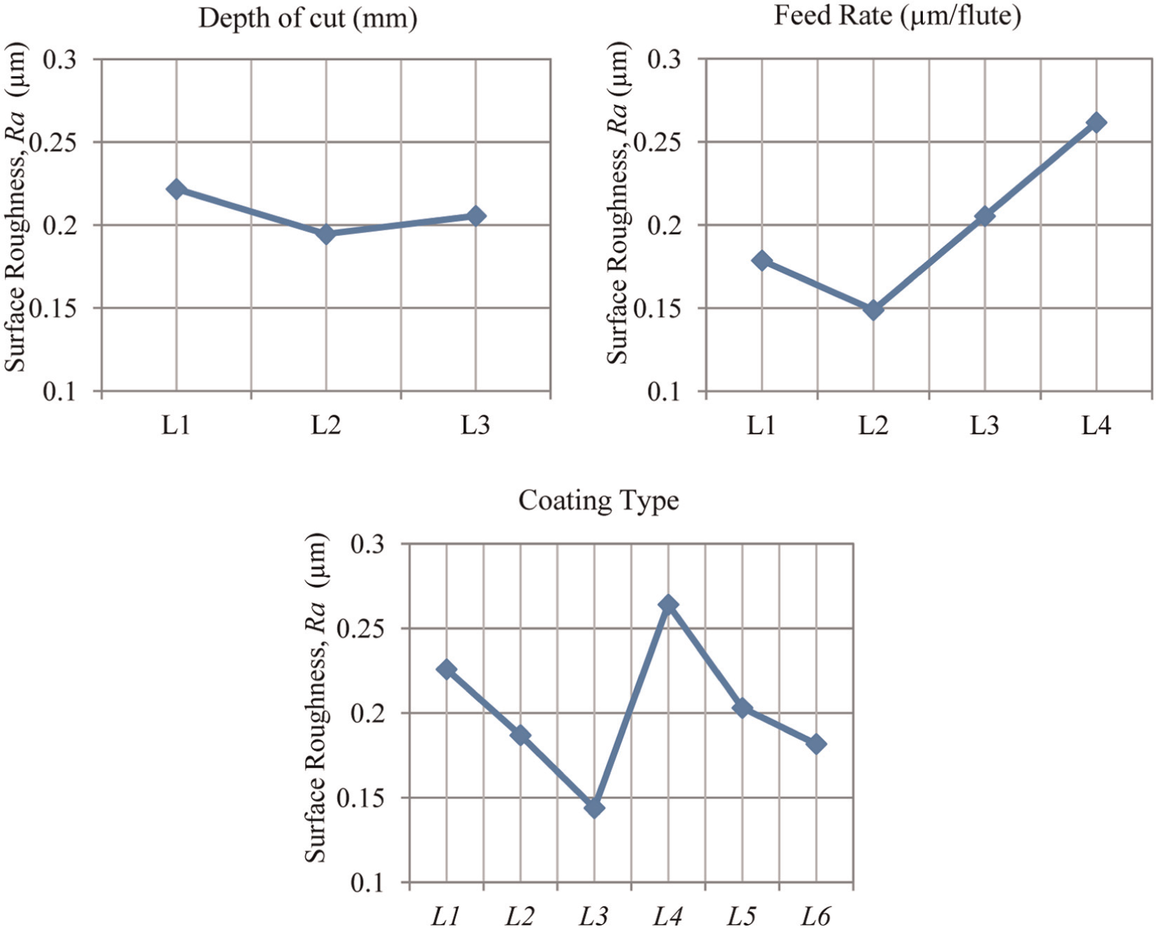
Average surface roughness at different levels of each design factor.
Lowest surface roughness value factors and levels.
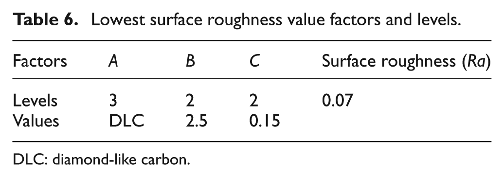
DLC: diamond-like carbon.
Effect of cutting tool wear on surface roughness
Another result obtained at the end of the study was the change in surface roughness values depending on the cutting tool wear. In the evaluation carried out by taking the AlCrN-coated cutting tool as the reference, surfaces in areas at distances of 20 and 120 mm from where the cutting process began and finished were taken into consideration.
As a result of the assessment, the surface roughness value was found to decrease at a rate of 50% with increasing the cutting length. This is due to increasing the cutting edge radius depending on tool wear (Figure 7). As it is known, the feed rate and cutting tool edge radius values have a significant effect on surface roughness.13,39 Wear occurring at the beginning of the cutting process causes a growth in the cutting edge radius. 25 The increased cutting edge radius contributes to produce a better surface quality. This can be clearly observed in SEM images of tools used in the study (Figure 8), in addition to the graph given in Figure 7. The edge radius of the tool was obtained as 25 µm following a cutting process of Lc = 20 mm immediately after the beginning of the cutting process. However, at the end of the cutting process (Lc = 120 mm), the cutting tool edge radius was 45 µm. This effect of cutting tool wear on surface roughness is also observed in a study by Filiz et al., 25 who reported that the roughness value decreased with the increase in cutting length. As its cause, they suggested that the cutting tool wears and the edge radius grows as the cutting distance increases.
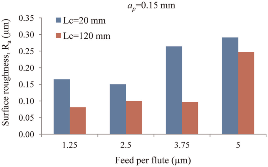
Variation of surface roughness with cutting length and feed per flute.
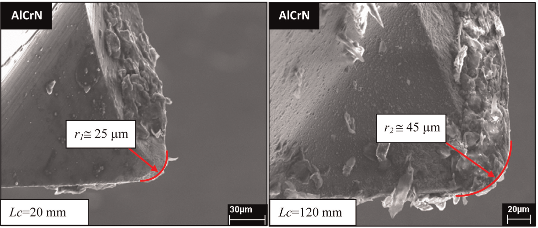
Change in the cutting edge radius with the wear on tool (f = 3.75 µm/flute and ap = 0.15 mm).
3D surface profiles obtained through the machined surfaces also clearly show the effect of tool wear (Figure 9). At the beginning of the cutting process, the surface was observed to be quite rough. Measurement carried out at the end of a 120-mm cutting process showed that a smoother surface was obtained. The maximum amplitude of the roughness curve of the surface at the very beginning of the cutting process was approximately 1 µm. However, at the end of the cutting process, the amplitude value was observed to be around 0.4 µm. The effect of tool wear and the cutting edge radius on the surface roughness is clearly observed in these results.
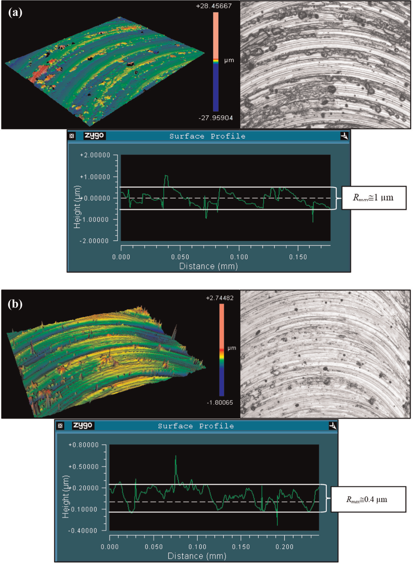
Surface profiles that change with tool wear: (a) cutting length, Lc = 20 mm and (b) cutting length, Lc = 120 mm.
Conclusion
This study investigated the performance of coated tools on surface roughness in micromachining of Inconel 718 nickel alloy. In general, it was observed that the coating material had a major impact on surface quality. It was concluded that the performance of the tools on surface roughness might be related with their resistance against BUE formation. An assessment conducted among coated tools made it clear specifically that the DLC- and TiAlN + WC/C-coated tools had the best surface roughness performance. The structural properties of these coatings contribute to this greatly. In addition, the propensity of tools to BUE formation was identified through analyses carried out in an SEM environment, on both the cutting tools and the machined surfaces, and it was observed that these results were in harmony with the surface roughness performance in each case.
However, it was also observed that the surface roughness value increased with the increasing feed rate. But it was concluded that the surface roughness value was not so much affected by the depth of cut. Wear occurring on the cutting tool was found to have an impact on surface roughness. A decrease in roughness values occurred with increasing cutting distance. There is an indirect effect of wear on this result, as the cause of the decreased roughness value was the growth in the cutting edge radius that resulted from wear.
The statistical analysis carried out on the experimental findings showed that the most effective parameters on surface roughness were the feed rate and cutting tool coating material. Depth of cut was not observed to have a significant effect.
Footnotes
Acknowledgements
The authors would like to thank Bilkent University, Motion Sensors and Micro System Technologies Expertise and Excellence Centre (HAMİT) and Dr Yiğit Karpat for his contribution to the experimental phase of this study.
Declaration of conflicting interests
The authors declare that there is no conflict of interest.
Funding
This work was supported by grants from the Scientific and Technological Research Council of Turkey (TÜBİTAK); from the Support Program for Scientific and Technological Research Projects (1001), project no: 213M572.