
Abstract
The development of the manufacturing-based industries is principally due to the improvement of various machining operations. Experimental studies are important in researches, and their results are also considered useful by the manufacturing industries with their aim to increase quality and productivity. Turning is one of the principal machining processes, and it has been studied since the 20th century in order to prevent machining problems. Chatter or self-excited vibrations represent an important problem and generate the most negative effects on the machined workpiece. To study this cutting process problem, various models were developed to predict stable and unstable cutting conditions. Stability analysis using lobes diagrams became useful to classify stable and unstable conditions. The purpose of this study is to analyze a turning process stability using an analytical model, with three degrees of freedoms, supported and validated with experimental tests results during roughing operations conducted on AU4G1 thin-walled tubular workpieces. The effects of the tubular workpiece thickness, the feed rate and the tool rake angle on the machining process stability will be presented. In addition, the effect of an additional structural damping, mounted inside the tubular workpiece, on the machining process stability will be also studied. It is found that the machining stability process is affected by the tubular workpiece thickness, the feed rate and the tool rake angle. The additional structural damping increases the stability of the machining process and reduces considerably the workpiece vibrations amplitudes. The experimental results highlight that the dynamic behavior of turning process is governed by large radial deformations of the thin-walled workpieces. The influence of this behavior on the stability of the machining process is assumed to be preponderant.
Keywords
Introduction
Many studies have been conducted during these last decades to analyze the influence of various parameters on the turning process. The adopted methods are numerous, but they are within three important families: experimental, analytical and numeric (FEM). Their common objective is cutting process optimization and the study of the effect of some cutting and tool parameters on the machining process.
Process vibrations or chatter represents an important problem for machining operation reflected by process instability and negative effects on productivity performance. Due its negative results, many studies focused their tests and analysis on this issue in order to understand its link with the dynamic workpiece behavior, material properties, tool geometry and cutting parameters (such as depth of cut, feed rate, cutting speed or spindle speed). One of the study methods is the process stability analysis based on the delimitation of some stability conditions (via graphic representation called stability lobes diagrams) for a well-defined system and according to its own characteristic parameters by using Laplace transform. Stability analysis combines analytical formulas of the cutting process, which helped researchers to establish various linear or nonlinear models in order to predict those stability zones during machining.1–4 Those analytical stability models represented an important way to study the cutting process vibrations phenomenon. It was possible for researchers to model the cutting process mechanism, the cutting specific factors and chatter due to the regeneration phenomena. Major studies of the process vibrations using stability analysis and cutting parameters prediction were conducted for a specific cutting-process. The stability models were simple, 3 and they were oriented to one or two degrees of freedoms to describe the interaction between the tool and the workpiece.
Other studies focused on the influence of the cutting parameters to introduce a dynamic model of stability in order to predict stable and unstable zones. In those models, regeneration process effect and damping process were also integrated to increase model precision.5–7 As we explained, stability analysis begins with modeling of the dynamic of the machining process via mathematic equations. Such studies are accompanied with analytical prediction of the cutting process parameters such as cutting forces or workpiece vibrations in time domain.8–12
Experimental results represent also an important support and regulator to the theoretical studies. With technological development, many parameters can be measured to clarify various parameters dependency like the influence of the depth of cut and the spindle speed same as the stability analysis theory. In addition, experimental approach can be deployed to study the influence of cutting parameters (cutting speed, feed rate and depth of cut) on cutting operation and to identify the main parameters that affect cutting forces. 13 Another experimental study of orthogonal turning (facing) and normal turning was conducted during stable and unstable (controlled chatter) cutting process. 14 The effects of chatter vibrations were also analyzed using frequency domain methods. It was shown that chatter vibrations are located close to the dominant mode (natural frequency) of the machine tool system. 15
The aim of this article is to analyze a turning process stability using an analytical model, with three degrees of freedoms, supported and validated with experimental tests results during roughing operations conducted on AU4G1 thin-walled tubular workpieces. The effects of the tubular workpiece thickness, the feed rate and the tool rake angle on the machining process stability will be presented. In addition, the effect of an additional structural damping, mounted inside the tubular workpiece, on the machining process stability will be also studied.
The article is organized as follows. The basics of dynamic cutting process model are reviewed in the next section. The stability analysis model is presented in the “Stability analysis model” section. The experimental setup and test conditions are presented in the “Turning process stability analysis and results discussion” section. In this section, the turning process stability analysis and results of the experimental tests are discussed. The article is concluded with the main observations and potential future work.
Dynamic cutting process model
The study of the dynamic cutting process goes through the analysis of the physical aspects that link various parameters specially the cutting efforts, depth of cut, and spindle speed. The analysis of this process and its stability starts with theoretical process modeling by including geometric, cinematic and dynamic parameters. In fact, the purpose is to delimit the stable and unstable zones of the cutting process in function of the chosen parameters.
Dynamic chip geometry model
The first parameter considered in our model is the chip geometry. In fact, in a turning process, after each revolution of the workpiece, vibrations generated during the machining process affect the cutting tool position. Because of the cutting tool previous pass, continuous undulations are present along the contact surface between tool and workpiece. Thus, the chip geometry is described via the chip load that represents the area between two cutting edges of present and previous revolution.
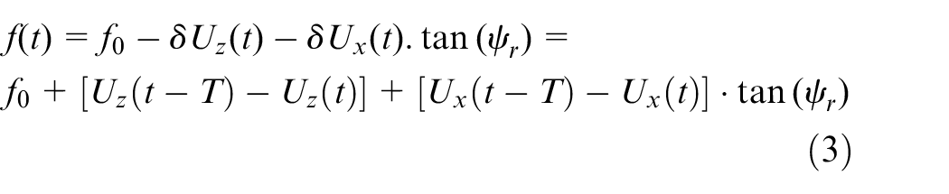
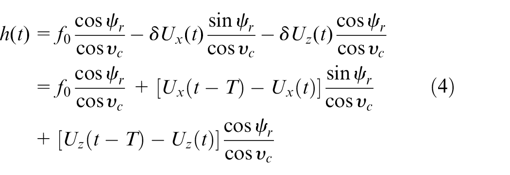
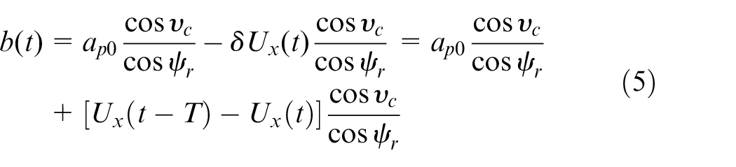
The chip load expression is expressed as follows

where
Instantaneous depth of cut

Instantaneous feed rate
Instantaneous equivalent chip thickness
Instantaneous chip width
where
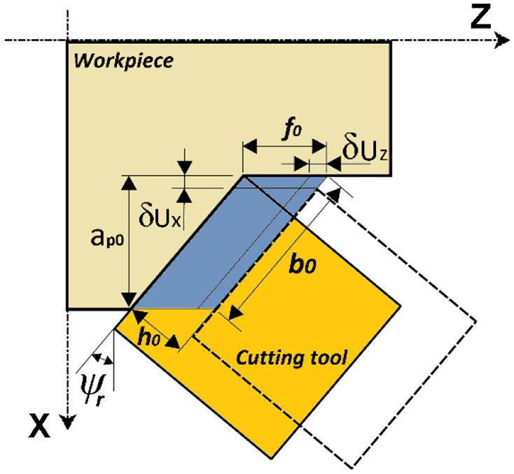
Chip geometry model.
The terms
The parameter
After substitution, the expression of the chip load becomes as follows

where
The two terms
Dynamic cutting forces model
The second parameter is the dynamic cutting forces model, which describes the resistance of the workpiece material to machining and the process damping. For a single cutting point operation, the oblique cutting model presented by Figure 2 is used to represent the cutting force components. In this model, the tool geometry and the chip formation parameters are taken into consideration.
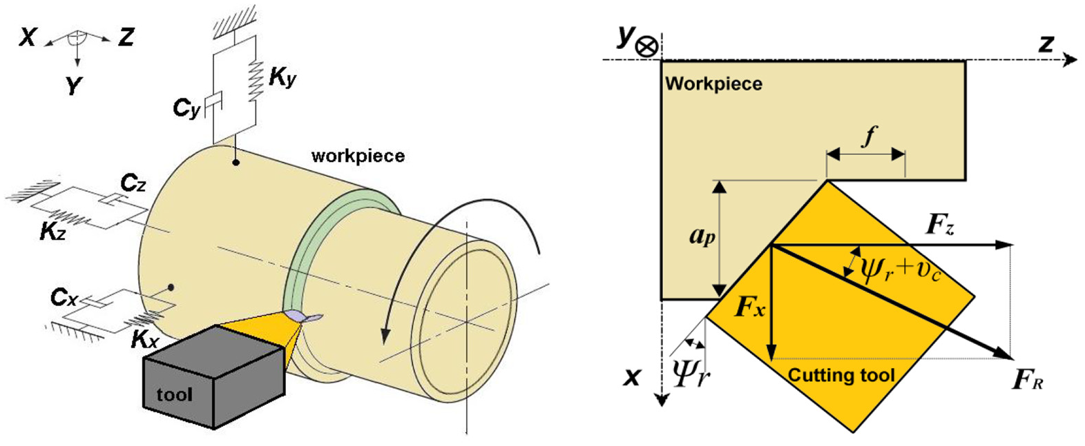
Cutting forces model description.
The resulting force acting on the structure is composed of a tangential force along cutting speed direction, a radial force along cutting edge and an axial force perpendicular to cutting edge. By using geometrical parameters (chip flow angle, approach angle, etc.), these components are expressed in
The first force responsible of metal removal process is the metal cutting force
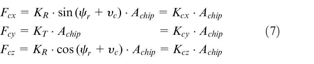
where
According to previous studies during cutting process, a waved surface is the result of tool and workpiece contact mechanism caused by the regenerative effect. The cutting tool interacts with the workpiece along clearance surface and may follow a sinusoidal path. It adds damping effects to the process, and this will affect also the vibrations. It is the second force called the dynamic damping force generated proportional to the vibrations velocity.17–23 The components of the cutting damping force along
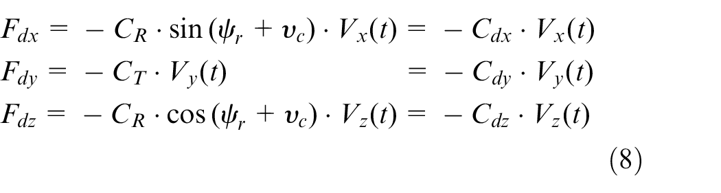
where
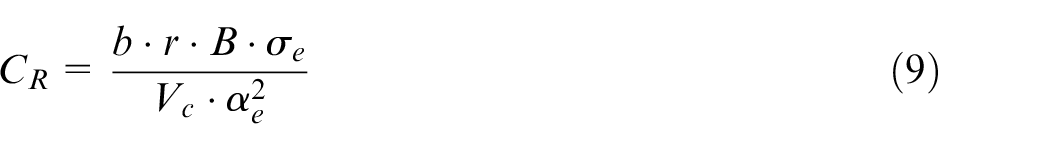
where
The effective (instantaneous) rake and clearance angles variation is opposite: when effective rake angle
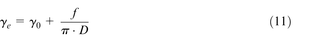
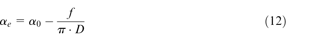
where
Dynamic turning process model
The model of the dynamic turning process is presented by a dynamic system with three degrees of freedom. In this system, the deformable tubular workpiece is modeled by a mass-spring-damper system and the tool is considered as rigid body. With the appropriate boundary conditions, the process equations of motion are analyzed along
Here,
The following equations of motion along the three global directions describe the dynamic response of the cutting process
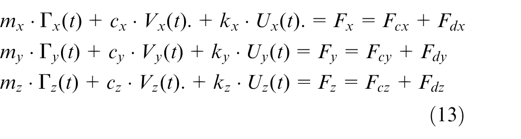
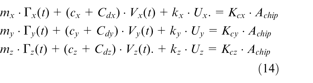
According to equations (6) and (8), and in order to study the effect of the cutting process damping and the cutting forces on the machining process response, the above expressions of equation (13) can be arranged as follows
Time-domain analysis procedure
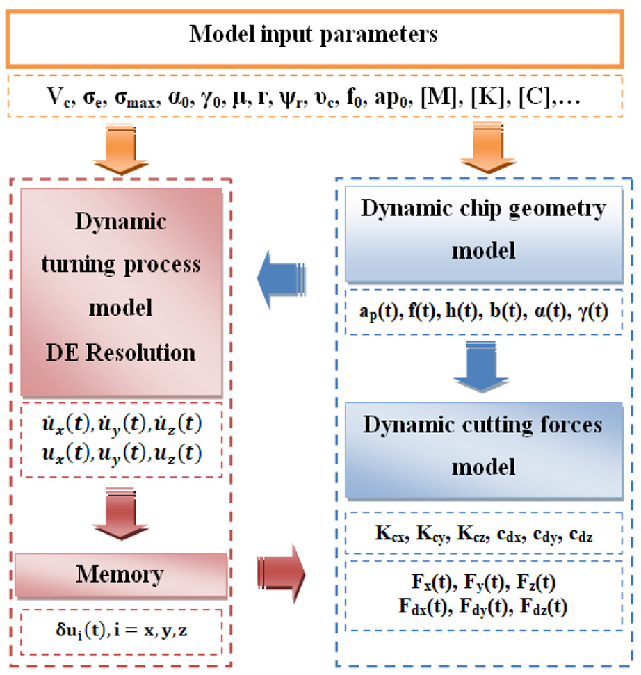
The analysis in time domain is a numeric resolution of the three differential equations (equation (14)) using Maple software. Figure 3 describes the resolution block diagrams of equation (14). Each component of this diagram is equivalent to a maple procedure developed to calculate specific parameters:
First procedure: Selection of input parameters:
– Input: workpiece (geometry, material parameters), Tool (geometry, angles), initial cutting parameters (feed, depth of cut, cutting speed).
– Output: workpiece (geometry, material parameters), Tool (geometry, angles), initial cutting parameters (feed, depth of cut, cutting speed).
Second procedure: Dynamic chip geometry and cutting efforts models (analytical expressions):
– Input: the output of “Selection of resolution parameters.”
– Output: chip load expressions and cutting forces expressions function of the delay factor, chip load and cutting forces values.
Third procedure: DE Resolution (maple dsolve command with the option numeric):
– Input: the output of “chip load and cutting efforts analytical expressions,” workpiece properties (mass, stiffness, damping factor).
– Output: workpiece displacement and velocity vectors.
Using cutting forces expressions, the values are calculated analytically for arbitrary state vector taken into consideration the delay factor.
Dynamic model analysis.
Stability analysis model
Stability analysis remains an important study to understand the cutting process with its various parameters. In order to identify stability limits or stability zones, it is necessary to pass by Laplace domain. It is possible also to represent the cutting system vibrations by a block diagram including cutting process, delay effect and cutting structure as described in Figure 4.
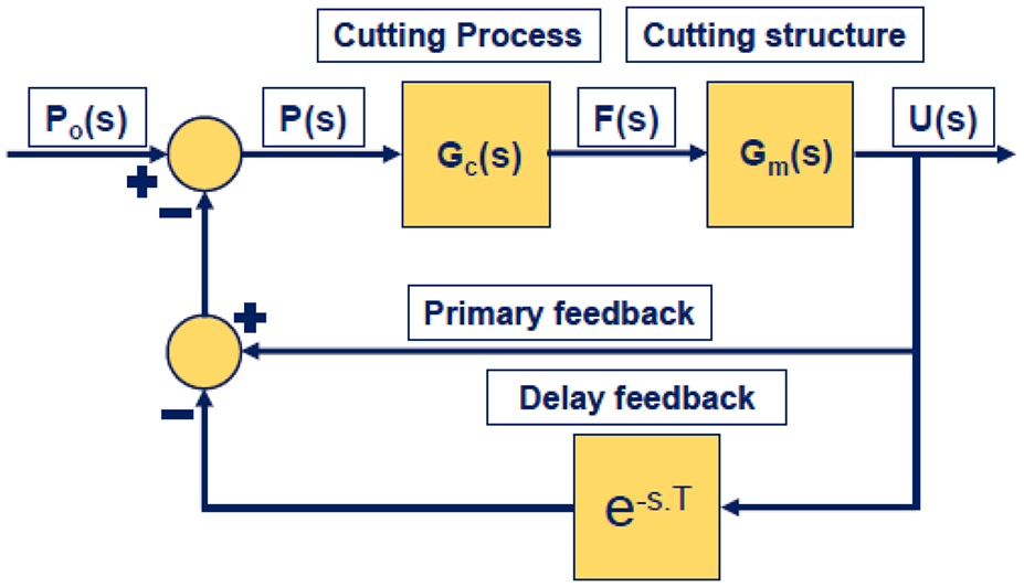
Block diagram for the turning system.
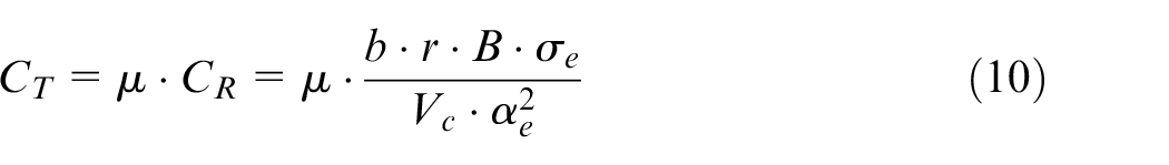
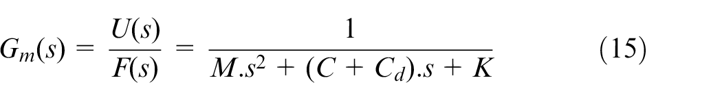
The open loop or normalized dynamic compliance of the cutting structure
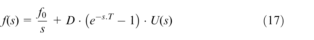
The closed-loop transfer function that links the dynamic and the reference value of the cutting parameter (feed rate) is arranged as follows
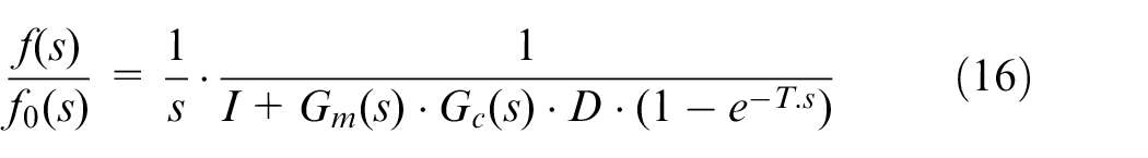
where
In order to identify the process stability zones, we should determine the roots of its below characteristic (equation (18))

The solution of the characteristic equation can be written as
The solution of the characteristic equation identifies the stability border function of depth of cut limit and spindle speed.
By substituting

By considering
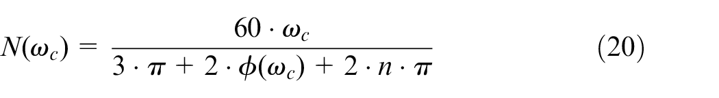
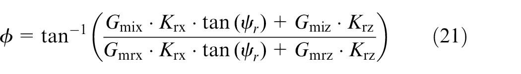
where
The real term will be exploited to identify the critical depth of cut at stability boundary limit. For a certain chatter frequency, its expression is given by equation (22)
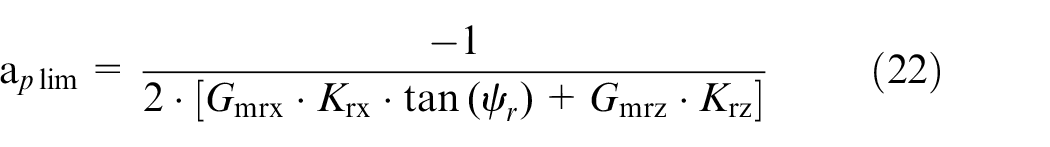
Using the equation of the critical depth of cut and the spindle speed, we will construct the stability lobes diagram.
Turning process stability analysis and results discussion
In this section, we will analyze the stability zones of thin-walled tubular workpieces through the model results and we will discuss their correlation with the experimental ones. Thus, the first subsection deals with the presentation of the machine devices and the cutting parameters used in carrying out the experimental tests as well as the acquisition of the cutting forces and vibratory signals of the workpiece.
The second and the third subsections will present an analysis and discussion of the effect of the wall thickness of the workpiece, the feed rate and the tool rake angle on the stability zones of the thin-walled tubular workpiece in a turning process. This analysis will be carried out on the basis of results obtained by the model and consolidated by the results of the experimental tests.
Based on this analysis, the fourth subsection will provide a practical solution for thin-walled parts manufacturers to improve the stability zones of the cutting process. This solution is verified numerically by the model and approved experimentally.
Turning process parameters
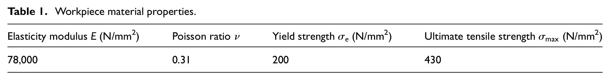
Table 1 gives the material properties of the tubular workpieces used in our numerical and experimental tests. This is the AU4G1 aluminum alloy that is widely used in aircraft construction because of its good mechanical properties.
Workpiece material properties.
During experimental tests, the stability process is detected using cutting forces measurements using tri-axial force piezoelectric dynamometer (Kistler) along the three directions
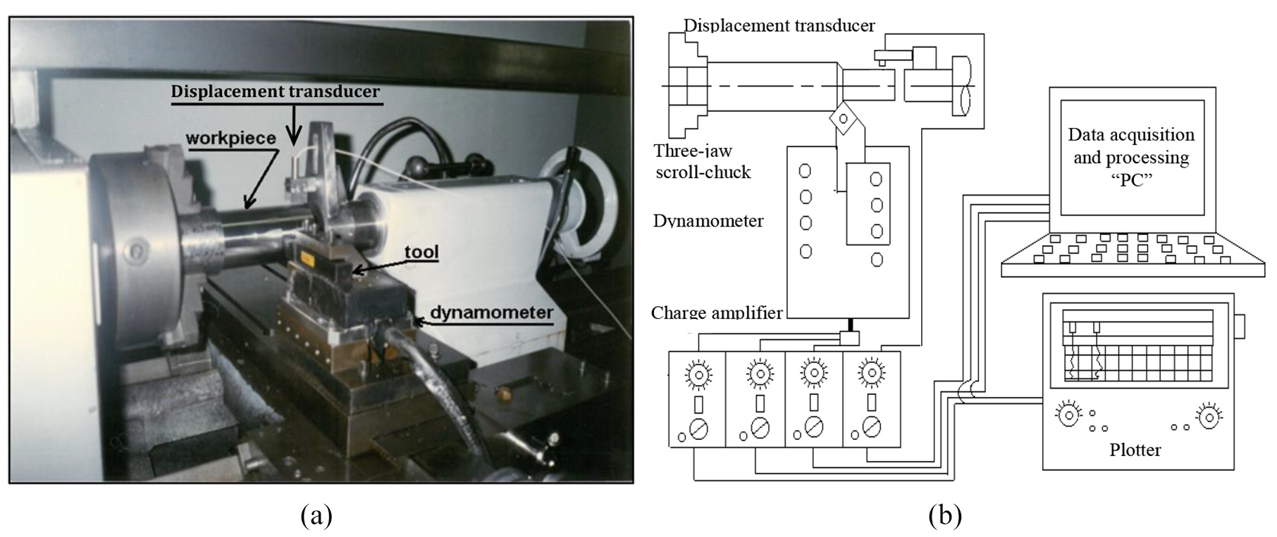
Experimental turning device: (a) Details of the turning machine. (b) Data acquisition and processing chain.
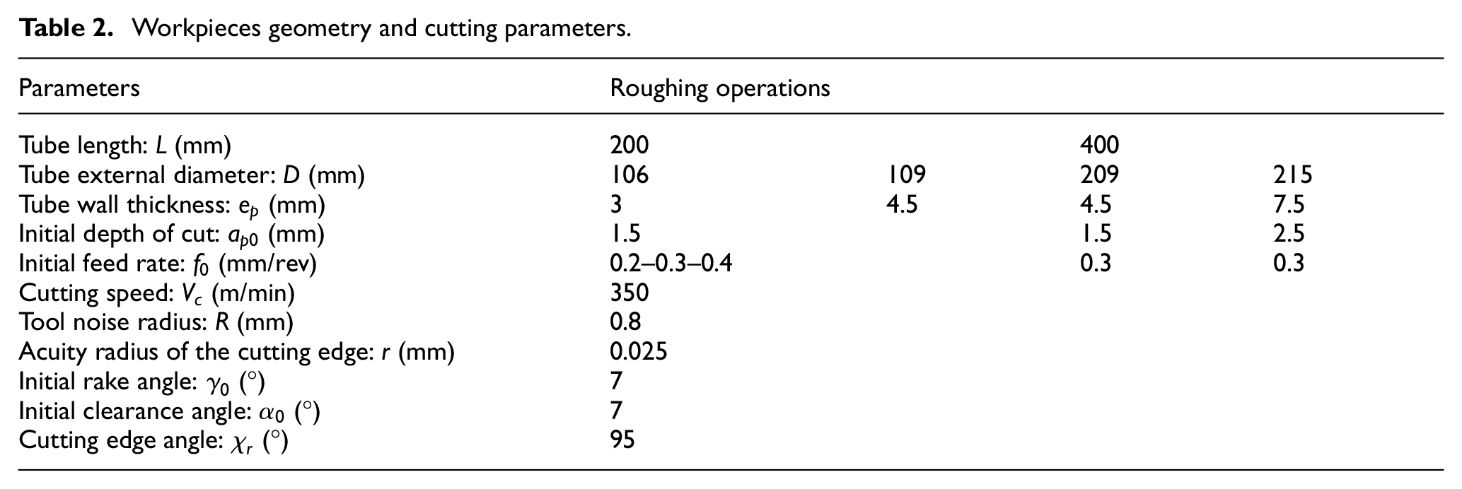
The details regarding workpieces geometry and the cutting parameters are described in Table 2.
Workpieces geometry and cutting parameters.
Stability analysis
The stability lobes diagrams are the results of the combination of equation (1) and equation (21). Respecting the root condition, by varying the value of the spindle speed
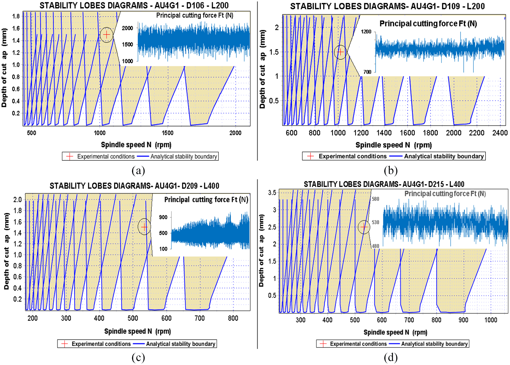
Stability lobes diagrams for roughing operations: (a)
For the roughing operations, the stability lobes diagrams are drawing according to the details presented in Table 2. The common observation for the different workpieces is the limited area of the stable zone. For the tubular workpieces, the absolute stability regions (located below the straight line passing through the minimums of the lobes) are very narrow. For this, the choice of the high values of the depth of cut is located between the successive branches of the neighboring curves. Thus, the choice of an optimal value of the depth of cut is a function of the limited range of the spindle speed. Those discontinuous intervals do not offer wide combinations especially for low spindle speed. For higher values, the possibility of depth of cut theoretical choice increases considerably until reaching 1.5 mm in the case of
For the machined workpieces, the experimental parameters relative to turning tests define a process located in unstable zone as indicated in the different curves of Figure 6. The experimental principal cutting force (along cutting speed direction) time varying curves confirm the instability of the experimental cutting tests characterized by important continuous fluctuations. For the most workpieces, the process is unstable and practically with the experimental spindle speed, it is not possible to have a stable process. Thus, in order to get stable process we should consider other values for the combination of spindle speed and depth of cut:
For the workpiece with a wall thickness and length values respectively equal to 3 mm and 200 mm, we could have stable process using “1000 rpm, 0.5 mm” or “1150 rpm, 0.6 mm” combinations.
For the wall thickness and length values respectively equal to 4.5 mm and 200 mm, the combinations for stable process could be “955 rpm, 0.7 mm” or “1060 rpm, 0.8 mm”.
For the workpiece with a wall thickness and length values respectively equal to 3 mm and 400 mm, we could have stable process using “538 rpm, 0.9 mm” or “647 rpm, 1 mm” combinations.
For the workpiece with a wall thickness and length values respectively equal to 7.5 mm and 400 mm, we could have stable process using “495 rpm, 0.9 mm” or “568 rpm, 1 mm,” and even “796 rpm, 1.6 mm” combinations.
The conical areas of stable domain depend of the workpiece geometry as described in Figure 7. In fact, for the same length value, if the wall thickness increases the stability curves move horizontally to the right zone of the higher spindle speed. The conical stable areas for the higher thickness value offer higher peaks values and wider range of spindle speed. More combinations are accessible with those dimensions. Workpiece dimensions variation is equivalent to part structural parameters change (mass, stiffness, damping). Those elements are implemented into the transfer functions adopted to study the stability of the cutting process. For a tubular workpiece, the stiffness is proportional to wall thickness for a constant length. This horizontal translation is due to increase of workpiece stiffness and mass.
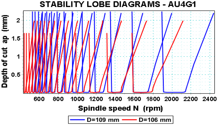
Stability lobes diagrams for different workpiece thickness (roughing operation).
Any increase of part stiffness is automatically accompanied with natural frequency increase. For a fixed workpiece dimensions, in addition to its geometry there are various parameters that affect the process stability. We choose to study the effect of two parameters: the first parameter is the rake angle related to the tool geometry and the second is the feed rate as a cutting parameter. The analysis was conducted for a tubular workpiece with external diameter value equal to 109 mm.
Figure 8(a) shows that the increase of the rake angle from negative value (–10°) to positive value (+20°) improves the conical stable zone between the adjacent curves. In fact, its range increases and becomes wider and higher, while the absolute stability area remains negligible because the curve of stability displacement upward is slight. Thus, positive rake angle values improve the choice of depth of cut in stable zones.
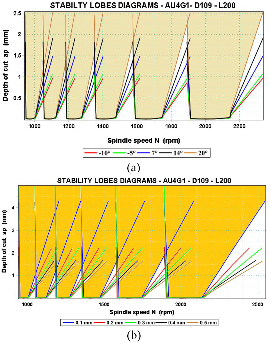
Cutting parameters effect on stability domain: (a) Rake angle effect. (b) Feed rate effect.
For the value of +20°, the depth of cut in stable domain can reach the value of 2 mm for a spindle speed equal to 1880 rpm. For the depth of cut equal to 1.5 mm (the same value as adopted in experimental procedure), the spindle speed range is between 1844 and 1889 rpm equivalent to cutting speed limited between 631 and 646 m/min. The increase of the rake angle toward positive values improves machining acuity and decreases the principal cutting effort along cutting direction. From previous experiences, increasing the rake angle (positive value) is suitable for elastic material, with good machinability and low stiffness. Stability lobes diagrams give information about the process vibrations boundaries, but additional parameters could affect also the choice of the data extracted from those diagrams.
Figure 8(b) shows that it is better to apply low feed rate values to improve stable zones between adjacent curves. We remark that the right branch of the lobe moves upward while the left branch present a slight translation leftward and the absolute stability areas remains the same and negligible. Thus, lobes diagrams are sensitive to high frequencies range in frequencies domain where the real part of the characteristic equation (equation (19)) is negative. For the same spindle speed value, the depth of cut can improve considerably. For example, for a 1047 rpm, the depth of cut value can improve from 0.34 mm at a feed rate equal to 0.5 mm/rev to 0.9 mm at 0.1 mm/rev. Those improvements confirm the fact that in turning process we have tendency to use low feed rate even in roughing operations. Low feed rates have a great effect on surface quality. But in any production process, the machining time, which is influenced by the choice of the feed rate, should be considered during process parameters choice. We can note also that high cutting speed values decrease tool life during machining.
Figure 9 shows the experimental results of the principal cutting effort (along cutting speed direction). We can see the increase of the fluctuations with the feed rate. This confirms the results described by the lobes diagrams in Figure 8(b).
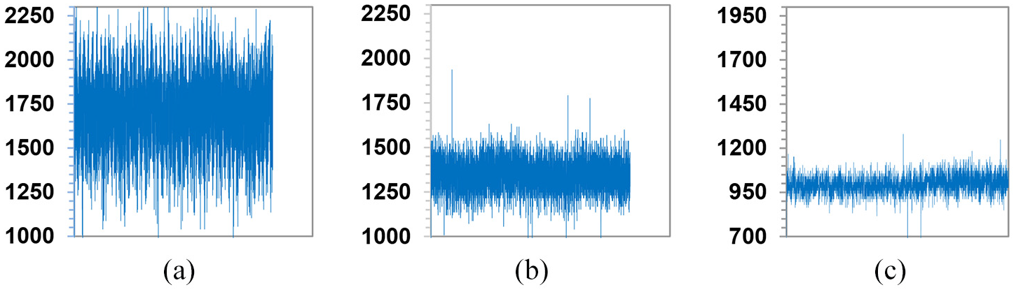
Principal cutting force
Time-domain analysis
In this section, we present time-domain simulations results for the turning process related to the details shown in Table 2 and to the dynamic model analysis described by Figure 3. Measured and simulated results are along
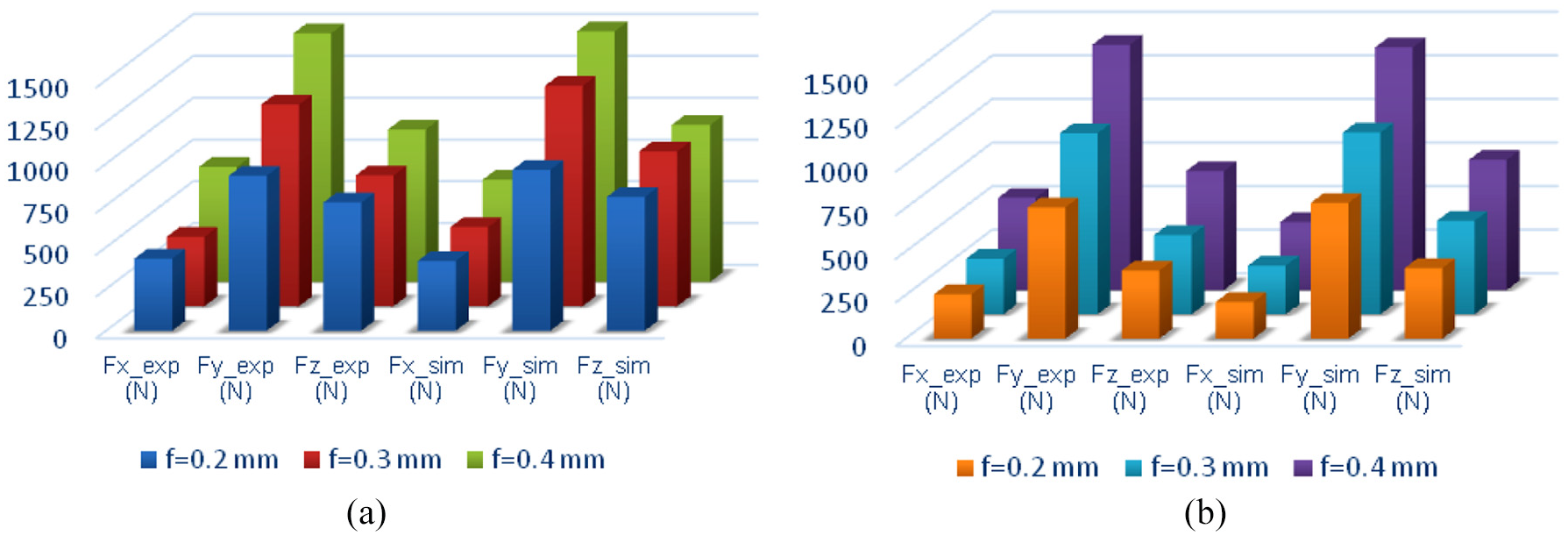
Cutting efforts components (experimental & simulation results): (a)
By examining the results of the roughing operations, it is seen that the cutting force components magnitudes are increasing with feed rate value along the three axes
The difference in values can be explained by various parameters. In this model, the effects of temperature or the tool wear are not taken into consideration. Such parameters have different effects on machining process. Furthermore, we remark also that for the same cutting conditions (tool geometry, feed, cutting speed, depth of cut), the influence of the wall thickness on the cutting forces values is significant because of the flexibility of the thin-walled workpieces. Thus, the chip removal process depends not only of material hardness but also of the dynamic behavior of these thin-walled workpieces.
Stability solution for thin-walled tubular workpieces
In this section, we present a practical solution adopted to reduce vibrations during turning process of thin-walled tubular workpieces. After the analysis of some parameters presented in the previous sections and in addition to the obtained experimental results, we remark that vibrations reduction requires not only good parameters choice but also structure characteristics improvement. This is possible using an additional structural damping mounted on the workpieces during machining. The additional structural damping consists of a rubber tube having the same length and internal diameter of the workpiece. The tube thickness is greater than that of the machined workpiece by 10 mm to guarantee high friction and no sliding between the two components (difference in thickness contributes to the automatic fixing between the two tubular workpieces).
We start with plotting lobes diagrams function for additional damping effect. Thus, for purely descriptive purpose, we assume that such structural damping will affect damping matrix coefficients through the damping ratio. This means, additional structural damping results in an increase of the damping ratio value. Figure 11 shows the lobes diagrams for different damping ratio values. We can remark that the stability boundary limit moved upward to the right side with considerable improvement of the absolute stability areas to offer an important wide range of choice even for low spindle speed corresponding to low cutting speed. Note that, the improvement in stability domain is more important with the damping ratio variation compared to the previous studied parameters.
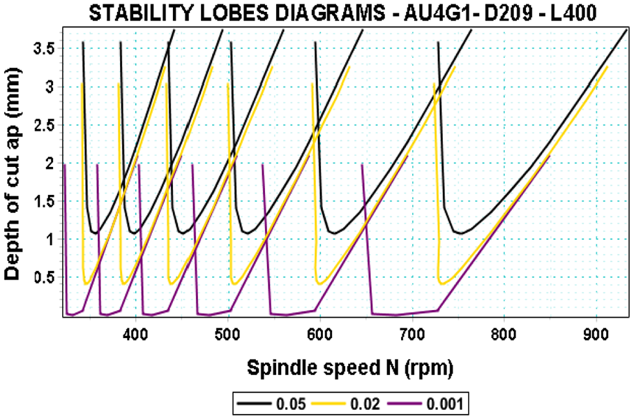
Effect of structural damping ratio on cutting process stability.
Experimental results confirm the above interpretations obtained following the analysis of the lobes diagrams data described in Figure 11. Thus, Figure 12 shows the difference in amplitude fluctuation of the principal experimental cutting force with and without additional damping. Cutting forces are tightly associated with system vibrations. That is why such results describe well the influence of this additional damping on system vibrations during machining process. The presented results show that the additional structural damping reduced considerably process vibrations along the
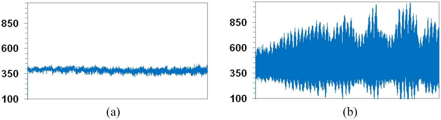
Effect of additional damping on principal cutting force (
Figure 13 shows the Fourier spectrum of the time signal corresponding to a stable machining process (with additional structural damping) and to an unstable machining (without additional structural damping).
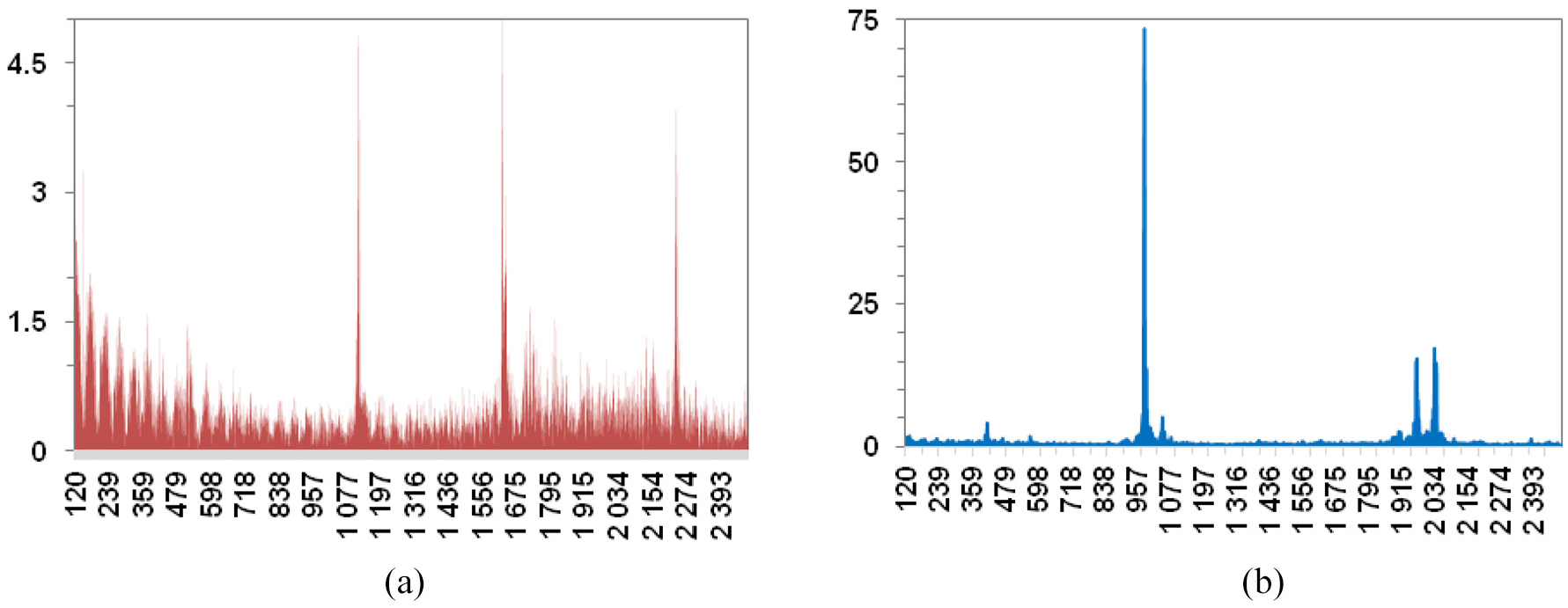
FFT diagrams of principal cutting effort (
In FFT spectrum there is a difference in scales between the stable cutting process (with damping) and unstable cutting process (without additional damping). In fact, from Figure 13(a), corresponding to the stable state, at the peak of the dominant frequencies, the amplitudes are much lower than the amplitudes obtained in the unstable process as described in Figure 13(b). These amplitudes are considered as parameters to categorize stable and unstable process.
The frequency corresponding to the highest amplitude in FFT graphic can be determined as tests chatter frequency of the workpiece during turning process under described conditions. The chatter frequency determined here is 1035.42 Hz.
Conclusion
In this article, an analysis of a turning process stability using an analytical model supported and validated with experimental tests results of roughing operations conducted on AU4G1 thin-walled tubular workpieces with different thickness values has been presented. The observations from this analysis can be summarized as follows:
The stability of the turning process is affected by the feed rate, the tool rake angle and the workpiece thickness values.
A low feed rate with positive rake angle values could increase the stability domain and facilitate the choice of the depth of cut that remains accessible for high spindle speed values. It has a negative influence on tool lifetime.
A low value of the workpiece wall thickness corresponds to low flexibility and higher tendency to vibrations during machining.
An added damping to the workpiece has a great effect on the stability process and the stable zones have been improved considerably making the choice of depth of cut value accessible even for low cutting speed.
The workpiece vibrations frequency is higher than the natural frequency or spindle frequency due to inertial factors during cutting process.
These results show the important effects of the dynamic behavior of the thin-walled workpieces on the stability criteria, which cannot be ignored in machining process planning and cutting parameters selection. The results may also be used in justifying the influence of an additional structural damping on chatter suppression in a machining of thin-walled workpieces.
Our future work is concerning the following subjects:
The establishment of the cutting process modeling from the view of material removal.
The study of the effects of additional cutting and tool parameters on the stability criteria within the turning process of thin tubular workpieces. A series of turning tests with different cutting conditions will be carried out in order to study their effects on cutting forces, surfaces integrity and tool life.
Footnotes
Declaration of conflicting interests
The author(s) declared no potential conflicts of interest with respect to the research, authorship, and/or publication of this article.
Funding
The author(s) received no financial support for the research, authorship, and/or publication of this article.