
Abstract
Tungsten carbides are extremely high in hardness and they are wear-resistant materials. However, they are extremely brittle materials that render them ideal for many applications. Brazing technology has been proved to be a promising approach for joining tungsten carbide to tough metals to create high strength, tough and impact-resistant joint in the final assembly. In this research work, a dissimilar brazing of tungsten carbide (WC-Co) and cold work steel will be achieved using a new type of filler, a silver-copper near-eutectic alloy (BAg-8T) (Ag70Cu28Ti2). (BAg-8T) as a mixed alloy (eutectic and titanium) can melt/solidify completely in a very narrow temperature range (778 °C/800 °C), lower than any other existing brazing filler alloy; this will reduce the possibility of partial fastening while solidification. In addition, (BAg-8T) filler will act as the soft-iron gauze. Being soft and ductile metals, they will creep and absorb the movement due to differential contraction of the carbide and tool shank. Besides, they will improve the wetting on the carbide. In this research work, the effect of the joining parameters (brazing temperature and cobalt percentage in the tungsten carbide) on the mechanical properties and microstructure of the brazed joint will be investigated to determine the best joint performance.
Keywords
Introduction
Tungsten carbides (WC) have received high attention as they have excellent characteristics in wear resistance, hot hardness, oxidation resistance, chemical stability and very low coefficient of friction to metals. Tungsten carbide (WC) contains equal percentages of tungsten and carbon atoms plus some cobalt as binder material. Using powder technology, tungsten carbide can be shaped into a variety of tools, to be used in a wide range of industrial applications. Tungsten carbide has double the density and twice the stiffness of steel, having a Young’s modulus of 530–700 GPa. WC can only be finished using very hard abrasive wheels like CBN and/or diamond.1,2
Tungsten carbide is well known for its properties of adequate fracture toughness because of the cobalt matrix. Recently, the properties of WC-Co have been highly improved. So far, WC-Co has been used in many industrial applications.2,3 Sintered tungsten carbide cutting tools are harder at high temperatures than high-speed steel tools. Tungsten carbide cutting tools are often used for machining harder materials, where other tools would wear away. Tungsten carbide is also used in armor-piercing ammunition and for making surgical instruments, for open surgery and laparoscopic surgery, giving better performance than other materials.3,4 In addition, it is commonly utilized for manufacturing the gauge blocks, producing precision lengths in dimensional metrology. 2
To extend their industrial applications and to produce bigger and/or more complex tools, it is necessary to join WC-Co to metals to create high strength, tougher and impact-resistant structure in the final assembly, as the tungsten carbide is an extremely brittle material.5–10 Besides, WC-Co is an expensive material, and thereby it would not be economically possible to consider making the whole cutting tool from this refractory alloy. In this work, the WC-Co will be bonded to cold work steel shank, as it is a relatively cheap material and possesses high hardness from complex carbides. Brazed WC-Co/steel has been used in many industrial applications. Tungsten carbide is usually bonded on the tips of steel tool parts, as it is very hard and stays sharp, longer than metals. A great example of this will be a saw; the brazed tungsten carbide on the steel points or tips of the saw or other tools provides a large benefit down to the fact that it will remain sharper and a lot more reliable than steel or other metals. There is also a lot to be said for utilizing tungsten carbide when there is a lot of abrasion at the point of the tool. Advances in technology in the 1980s mean that brazing is now seen as a reliable way of bringing two metals together, and this means that tungsten carbide can be effectively applied to other metals without any fear of breakage or damage.5–7 The following seven tools are among the most popular tungsten carbide tools that can be found in use today; tungsten carbide inserts brazed steel in endmills, drills, partings, borings, burs and wear warts. It is not as though these seven tools are the only way to benefit from using tungsten carbide brazed steel, far from it. But if you are looking for the most common or popular use of these tools, you will not go far wrong with selecting these tools.5–10
Previous studies reported many techniques of joining tungsten carbide and metals, including ultrasonic welding,11–15 diffusion bonding15–18 and brazing.18–27 Brazing is a very promising technique to join the dissimilar parts. Brazing is a high-temperature joining process utilizing filler material to produce powerful joints, even between dissimilar metals. The American Welding Society (AWS) describes brazing as a joining process that causes the coalescence of metals via a brazing filler metal that has a liquidus temperature above 450 °C/840 °F, but below the solidus temperature of the base metal. At this high temperature, using suitable filler alloy, strong metallic alloys can be established to join dissimilar materials. However, to braze tungsten carbide to metals, there are two main challenges. One is that most of the metals have poor wettability with tungsten carbide. The other is how to accommodate the thermal contraction mismatch between tungsten carbide and metals, to minimize the residual stresses in the joint.27–31 These two challenges could be achieved by selecting the proper filler material.
In choosing the suitable brazing filler material, the factors that influence the type of brazing alloy must be considered. These factors include (a) the type of parent metal, (b) the type of joint to be produced, (c) the brazing temperature, (d) the brazing process and (e) the limitation governing the use of filler.30,31 In addition, filler metals used for brazing must have the property of being able to readily wet the basic metals at temperatures below the melting temperature of the latter, and in so doing metallurgical reaction with the surfaces. The molten filler metal should be able to flow into the gap between the brazing cavities by capillary effect, as shown in Figure 1. The design of the filler metal can be quite complex alloys, which are determined by the conditions needed.32–35 The common filler alloys that have been used in brazing of carbides are typically silver, copper, nickel, zinc and some additional elements. In the filler alloy, each element adds unique properties so that the alloy works better than any of the individual elements. Silver, copper and nickel yield the strength. Nickel also enhances the flow of the alloy. Zinc and cadmium are added to reduce the melting temperature of the alloy. Cadmium is also a very ductile, so it adds a softening effect to the braze alloy. 35
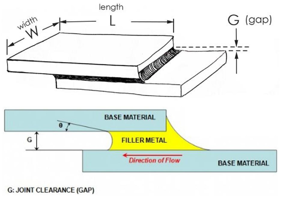
The schematic diagram of the brazing joint. 32
In brazing tungsten carbide to steel, three types of fillers are commonly used: silver and/or copper-based alloys, which is shown in Table 1.35–39 High ductility of silver and copper makes them favorable as the filler metal. This can compensate the irregularity in the thermal expansion.36,39 The standard filler used to be 50% silver with cadmium (BAg-3). 36 It has increased corrosion resistance in certain conditions (resistant to chloride corrosion). It is used extensively for brazing tungsten carbide tips on woodcutting, metal cutting and mining tools. It is recommended for aluminum bronze, as the nickel content offsets the detrimental effect of aluminum diffusion. However, it is mushy during melting, as most volume melts at the higher end of the melting range. It can be used to shape fillets and to bridge large gaps. However, using cadmium is dangerous; government’s policies restricted cadmium contamination. Later, the 50% cadmium-free filler (BAg-24) was introduced. 37 It is used for most metals, including stainless steel and carbides. It is recommended for 300-series stainless steel. It is good for food-handling applications with close joint tolerances (gap 0.1–0.25 mm). This alloy is specifically designed for brazing tungsten carbide tips to steel tools and wear parts. It readily wets nickel and iron alloys; the nickel offsets embrittlement by aluminum diffusion when brazing aluminum bronzes. It also retards interface corrosion where base metals can cope, is very fluid and quickly fills long narrow joints. It performs well, but not as good as the one containing cadmium (BAg-3); as it is highly ductile, it contributes to a softening effect as well as reduces the melting temperature. The cadmium-free brazing filler resulted in increased tip fracture, as it (BAg-24) did not provide the enough impact resistance. Later, (BAg-24) was replaced by high-impact braze alloy (BAg-22) (49% silver with manganese). It is the best available alloy now; it produces good wetting properties, strong, ductile joints to absorb shock and are safe because they are cadmium-free. However, zinc-free alloys should be proposed where there is a risk of dezincification.38,39
Filler alloys used in brazing tungsten carbide.
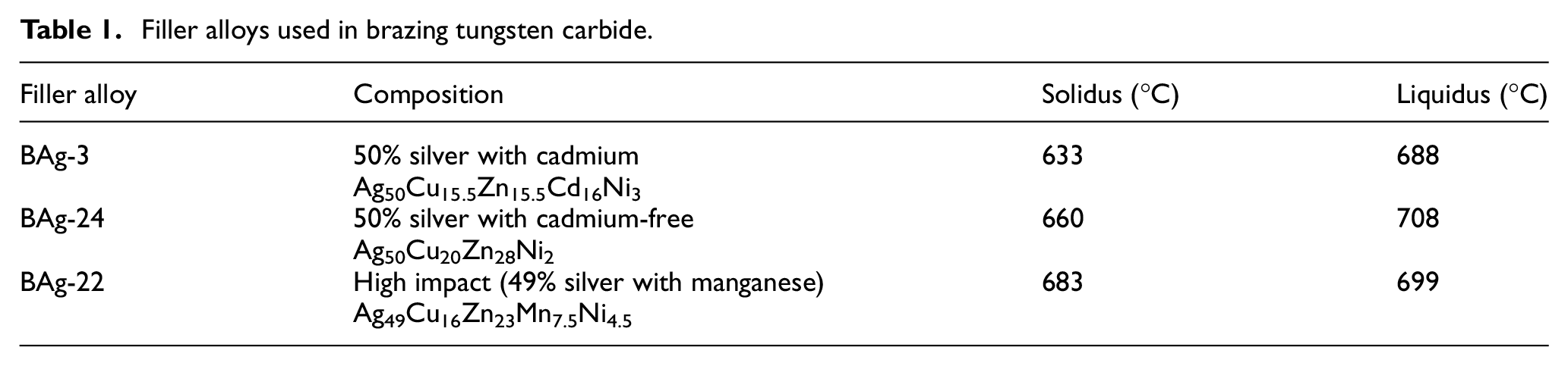
Furthermore, as can be seen in Table 1, the range between the solidus (filler alloy is fully solid) and liquidus (alloy is fully liquid) is called the melting range. In this melting range, there is a certain amount of plasticity of stretch produced in the material while it is cooling. In addition, it is hard to accurately identify when the filler is hot enough, to avoid having an insufficient heating, as it may cause a partial fastening (solidification) of the filler material. Heating over the melting range may help to avoid having an insufficient heating, but it is also important to avoid overheating the parts, as this can put heat stress in the tungsten carbide and put a chill line in the steel. More importantly, overheating can boil out components in the braze alloy. For these reasons, controlling the temperature close to the melting range is very important. Therefore, the shorter the melting range (between solidus and liquidus), the less likely there is trouble with the bond and the less the possibility of partial fastening resulting from insufficient heating. These conditions must be considered while selecting the suitable filler material.
This research work is proposing a new type of filler alloy, a silver-copper near-eutectic alloy (BAg-8T) (Ag70Cu28Ti2) for brazing tungsten carbide to steel, as it has shorter melting range than the other filler materials and it could improve the wetting on the carbide.36–39 Moreover, it is a zinc-free alloy, to avoid the risk of dezincification. The aim of the study is to investigate the combinations of brazing and joining parameters that result in the highest shear strength of the joint. These parameters will be analyzed to get the best joint performance in terms of shear strength, hardness and microstructure characteristics of the brazed joint between WC-Co and steel.
Material and method
Material and size of substrates
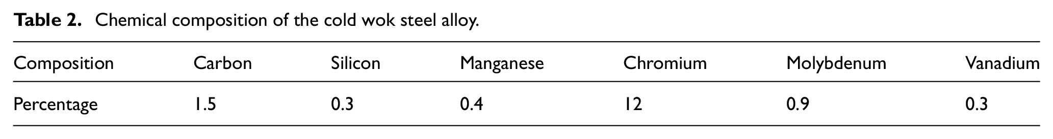
In this study, the mechanical properties and microstructure characteristics of the brazed joint between dissimilar materials of tungsten carbide and cold work steel were investigated. In this research work, there are three different compositions of tungsten carbide (WC-Co) with three different cobalt binder percentage contents (6%, 10% and 13%) have been used. These cobalt percentages are typically the available percentages in the most commercial tungsten carbide. As far as we know, the higher the level of cobalt percentage appearing in the tungsten carbide, the more ductile it will be. The other base metal used is cold work steel, a type of tool steel that undergoes cold-working process or more commonly known as work hardening process. The compositions are as shown in Table 2 and the size of the two substrates is illustrated in Figure 2.
Chemical composition of the cold wok steel alloy.
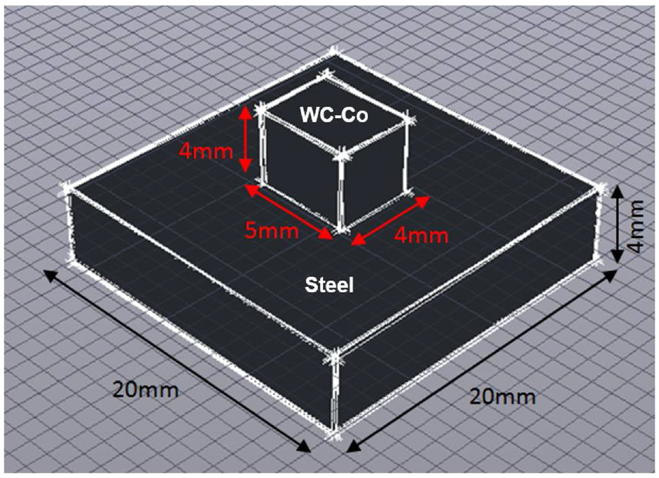
The sizes of the two substrates.
Brazing filler material, apparatus and method
Brazing filler material and clamping jig
The filler material selected is a silver-copper near-eutectic alloy (BAg-8T) (Ag70Cu28Ti2). It is a relatively new brazing alloy that has been improved from the older version of filler metals. The main advantages of the proposed filler (BAg-8T) as a mixed alloy (eutectic and titanium) over the others are that it will improve the wetting on the carbide36–39 and it is zinc-free alloy to avoid the risk of dezincification. Furthermore, the filler alloy elements could act together as the soft-iron gauze. Being soft and ductile metals, they will creep and absorb the movement due to differential contraction of the carbide and tool shank. Moreover, the (BAg-8T) has shorter melting range (778 °C/800 °C) than the other filler materials; this will reduce the possibility of partial fastening.
Figure 3 shows the silver-copper phase diagram. 40 The melting point of Cu is 1085 °C at point (A), whereas that of Ag is 961.8 °C at point (F). At point E, (Ag72Cu28) is a special eutectic composition alloy, where all the elements in that alloy can melt completely in a very narrow temperature range, lower than any other composition containing greater or lesser amounts of either metals.35–39 This will reduce the possibility of partial fastening resulting from insufficient heating. These behaviors apply to the cooling phenomena too. Eutectic alloy melts entirely at 778 °C. Adding titanium (Ag70Cu28Ti2) (BAg-8T) as an active element in silver-copper alloy improves the wettability of the braze joint at short melting range (778 °C/800 °C).40–43
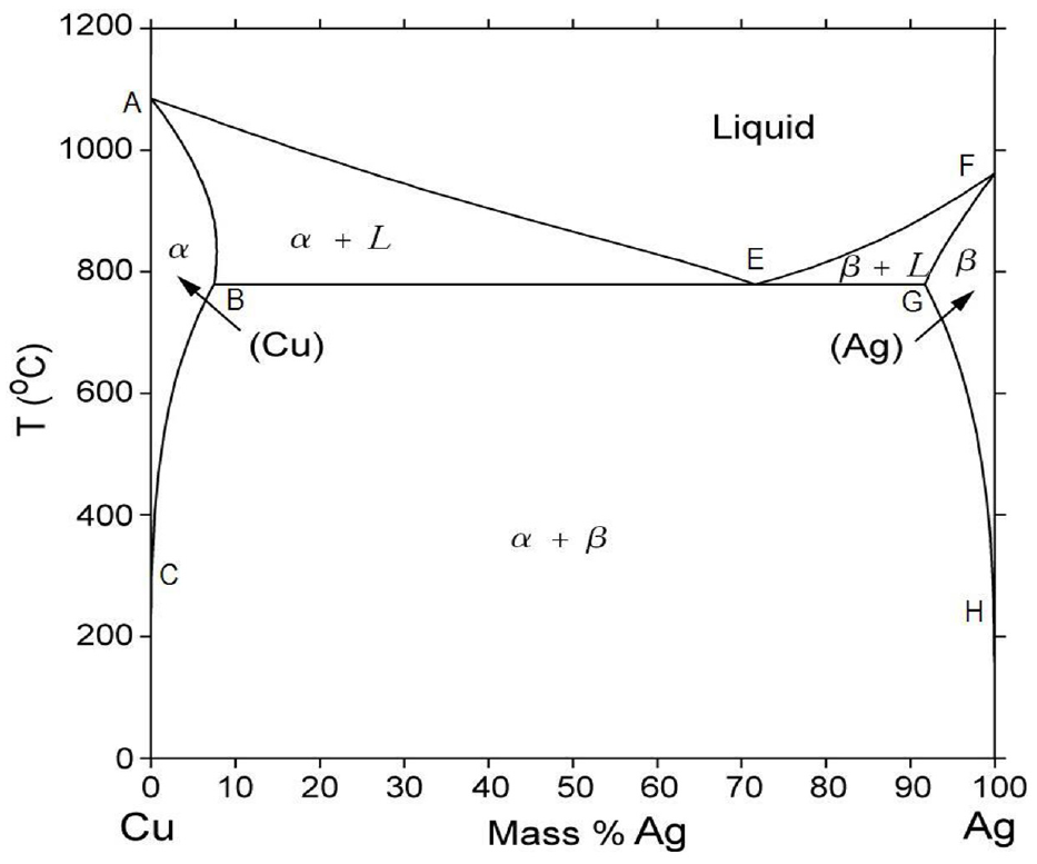
Silver-copper phase diagram. 37
In addition to BAg-8T filler material, a porous copper sheet, coated by active titanium hydride TiH2 (used to enhance the wettability) on both sides, is used as an internal stress eliminator, as it contains small voids and the pores are filled with gas. The selection of this type of porous sheet is based on its tendency to buffer stress generated, due to differing coefficient of expansion.38,39 The frame of the porous sheet is usually solid, but its structure is like foams and is often very ductile. It can absorb the stress induced in the joint. Being a soft metal, it will creep and absorb the movement due to differential contraction of the carbide and tool shank, so it can enhance the wetting on the carbide, and hence, this can compensate the irregularity in the thermal expansion. Meanwhile, the porous copper material is matching the copper element in the filler material (Ag70Cu28Ti2) (BAg-8T), so no more elements will be added to the filler material. The properties of the porous copper sheet used are as follows: the relative density (the ratio of the density of porous copper with the density of pure copper) of 0.36 ± 0.005, the porosity of 64% and the thermal conductivity of 68.7 (W m−1 K−1)
Figure 4 shows the design of the braze joint. The filler material and porous copper sheet thicknesses should be carefully selected to obtain suitable joint gap clearance (distance between the two substrates) as shown in Figure 1. Control of joint gap (clearance) is important, as the capillary forces that determine the filler metal flow (wettability) into the joint are strongly dependent upon the gap dimensions. Reduction in joint gap (clearance) enhances capillary forces and promotes wettability, although minimum limits exist. However, the joint gap should be identified as a compromise between the high strengths associated with very thin joints and the superior ability of thicker brazes to absorb thermal and mechanical strains acting on the joint.38–40
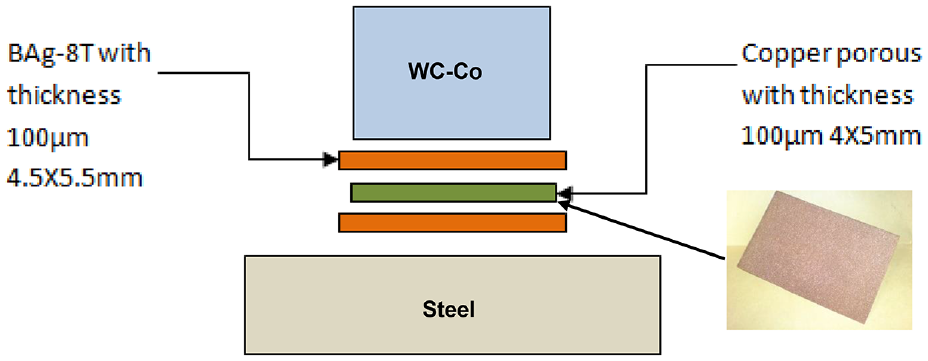
The design of the brazing joint.
From the preliminary experiment investigation at brazing temperatures between 800 °C and 900 °C, it is found that both wettability and shear strength are improved with the increase in the gap thickness, and then it is kept stable when the filler material and porous copper thicknesses are between 75 and 110 μm. But they decrease when the filler metal thickness is larger than this range, as the capillary forces will be reduced, leading to poor wettability. Based on that, in this research work, the filler material and porous copper sheet thicknesses used are 100 μm.
A stiff clamping jig made of stainless steel was used to clamp the brazing samples. Stainless steel was selected as the material for clamping, as it has high melting temperature and high resistance to bending on elevated temperatures and inert properties.41,42 Figure 5(a) and (b) shows the clamping jig used.
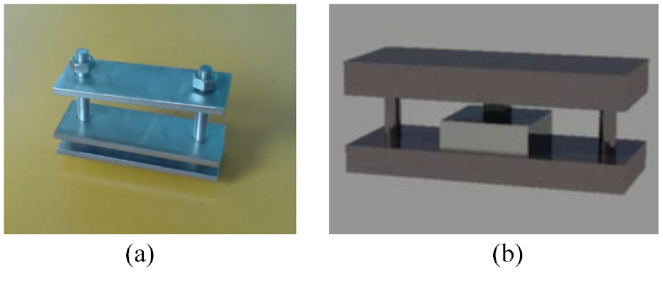
(a) Photo of the clamp jig used and (b) schematic diagram.
Apparatus and method
Figure 6 shows the vacuum furnace used as the heating source of brazing. Having a maximum operating temperature up to 1000 °C, this furnace can only accept specimen up to 60 × 60 × 60 mm3 in size. The furnace is a type of single-zone heating furnace that is located at the center of the tube. The vacuum mechanism operates with two different motor pumps, which are rotary and diffusion pumps, where rotary can produce vacuum environment of pressure of about ×10−2 Pa and diffusion pump can produce vacuum environment of about ×10−4 Pa. These motors allow the furnace to run under high degrees of vacuum during brazing. The brazing executes after the vacuum reaches ×10−4 Pa. The control system included is a DigitroniK controller, which can give signals to the heating coil. This controller can control the temperature with nine segments, with any ramp, set and dwell. The feedback of the temperature signal inside the furnace is easily monitored on the screen. Another alternative, a thermocouple, is installed to measure the temperature inside the furnace.
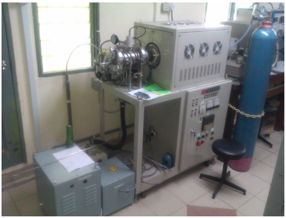
Vacuum furnace.
This furnace is used in the brazing of tungsten carbide to cold work steel. Investigation was done at different combinations of joining parameters, including cobalt binder percentage in tungsten carbide and brazing temperature; the experimental conditions of which are shown in Table 3. The two substrates are grinded and polished until Ra of 0.3 µm is achieved before proceeding to the chemical cleaning process. The brazing vacuum condition is constantly set to ×10−4 Pa for every set of specimens. These tests are repeated four times in each condition.
The experiment conditions.
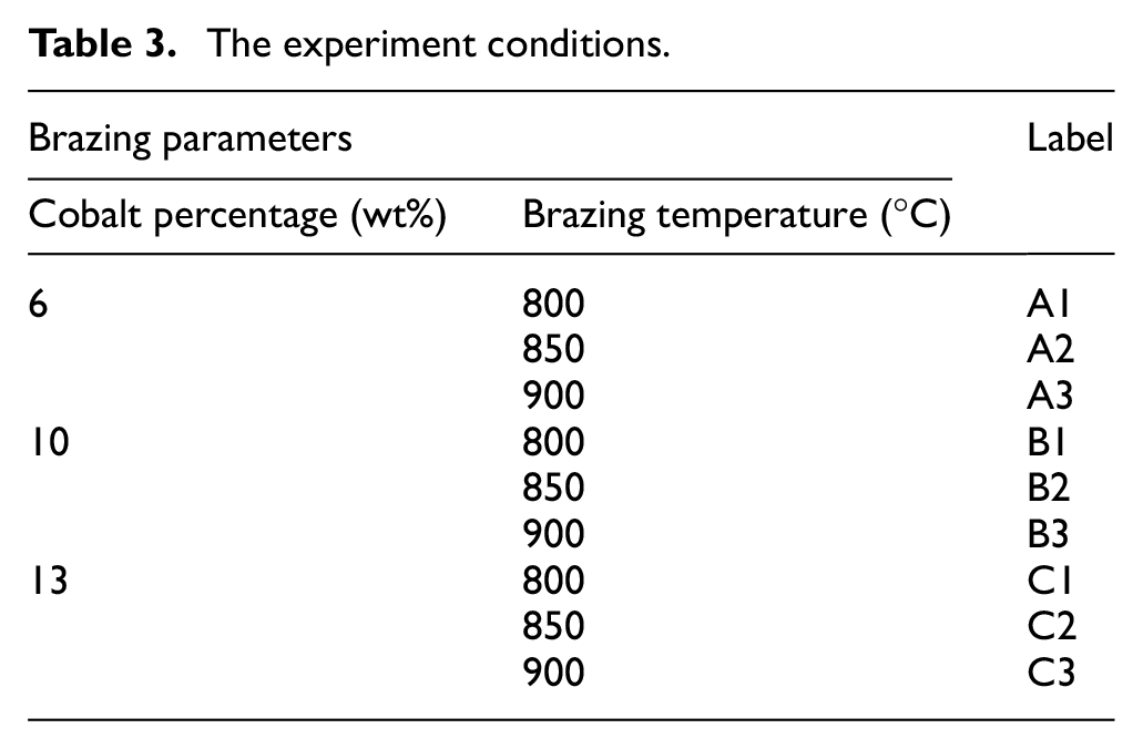
The brazing took place at different brazing temperatures under vacuum condition. These brazing temperatures (800 °C, 850 °C, 900 °C) were selected above the melting temperature of the filler materials (800 °C) that is obtained from the silver-copper phase diagram, which is shown in Figure 3. The brazing temperature of 900 °C is selected as the maximum temperature, as the vacuum silver may evaporate above (900 °C).37,41 The heating rate of the experiment is constantly set to 5 °C/min. All specimens will be heated to a temperature of 500 °C and then held at this temperature for 20 min. This action is needed to compensate the difference between the programmed temperature and the actual temperature. Figure 7 shows the brazing cycle diagram. Brazing time is fixed to 30 min, to avoid facing the liquation of the brazing filler, so that the best filler metal’s wettability can be achieved. Liquation happens when the eutectic alloy melts and fills the gap while the non-eutectic elements have not yet started to melt. 35 Finally, the qualitative measure of the filler’s ability to bond with a given base metal at brazing temperature is performed. The cooling process is done at a very slow rate inside a furnace.
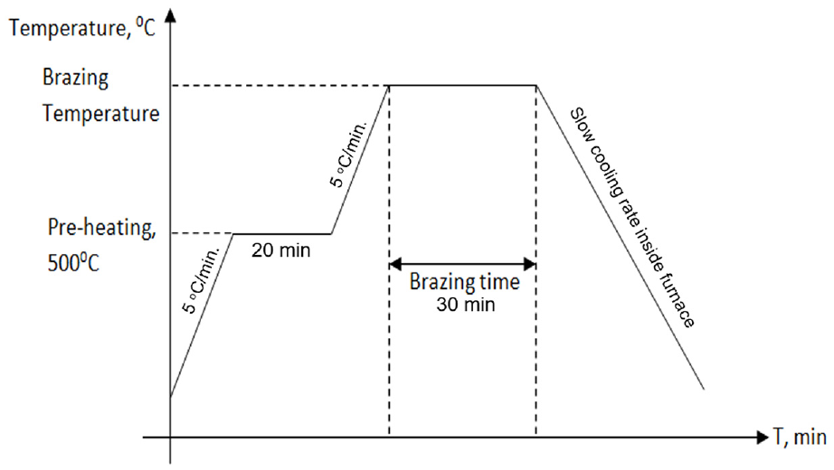
Brazing cycle.
Mechanical tests and microstructure analysis
Mechanical tests (shear strength and microhardness)
An Instron universal testing machine (UTM) was used to perform a shear strength test on the brazed joint. The specimen was clamped to a special design clamp with a specimen holder and a punch. The clamp is attached to the machine and the machine is operated at a constant speed of 10 mm/min. To obtain a set of precise results, each combination of joining parameters was tested three times.
Furthermore, the hardness of the cross section of the brazed joint was investigated by Shimadzu HMV microhardness tester. A load of 19.61 N and a duration time of 10 s were applied for all specimens. The microhardness was measured at eight different points on the cross section of the brazed joint as shown in Figure 8. For each point, an average of three measurements was taken.
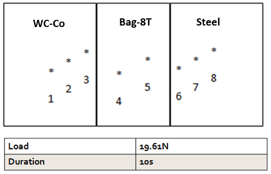
The location of eight points along the cross-sectional area of the brazed joint that tested by Vickers indenter.
Microstructure observation
For preparing the samples to perform the microstructure observation, the brazing joints were cut using the Sodick EDM Wire-cut Machine. The sample’s cross sections were ground using SiC 150-grit paper for 6 min at 300 r/min, and then using 240 to 4000-grit paper for 3 min for each at 200 r/min. Then, the samples were polished using 40 nm alumina particles suspended in ethanol using polishing cloth disk. After polishing, the sample’s cross sections were etched using 50% HCl at 75 °C for 5 s. Finally, the sample’s cross sections were cleaned using deionized (DI) water and ethanol in ultrasonic bath.
The surface morphologies of the samples were evaluated using FEI Quanta 200F field emission scanning electron microscope (FESEM). Using an EDX-System (Hitachi SU8000) instrument attached to an FESEM instrument, energy dispersive X-ray (EDX) analysis was performed to investigate the elemental composition of the samples.
Results, analysis and discussion
Shear strength results
Figure 9 shows the effect of higher cobalt percentages at different brazing temperatures on the shear strength of the brazed joint. As can be seen in Figure 9, at any percentage of the cobalt contents, shear strength shows a gradual increase with the increase in the brazing temperature. These behaviors happen due to the increase in the diffusion rate in both the base and the filler materials, when the brazing temperature increases from 800 °C to 850 to 900 °C. The effects of the diffusion rate vary widely in respect of the mechanical and physical properties of the joint and the parent metals. 39 Brazing filler metals adhere to the base materials by diffusion to obtain an effective brazed joint. 39 For a brazing condition of 800 °C, diffusion is almost insignificant. On the other hand, brazing temperature of 850 °C shows higher diffusion rate, enough to give a steep rise in the shear strength. Brazing temperature of 900 °C gives the best diffusion effect and obtains the highest value in shear strength compared with the other temperatures. The above observations accurately fit into the joints containing 6%, 10% and 13% of cobalt at all ranges of temperatures. However, for the joint (13% cobalt), a great fall in the shear strength happened when the brazing temperature was 900 °C. The reason is that at higher cobalt percentage contents in the tungsten carbide, more cobalt is encouraged to diffuse into the filler layer, exchanging copper and silver. Hence, a significant solid-state diffusion between the basic materials and the filler metal resulted in increasing the hardness of the filler metal, as cobalt is much harder than copper, and therefore introducing an inherent brittleness to the joint.36–39 This will be further explained with the result of the FESEM and EDX spectrum analysis in section “Microstructure analysis”.
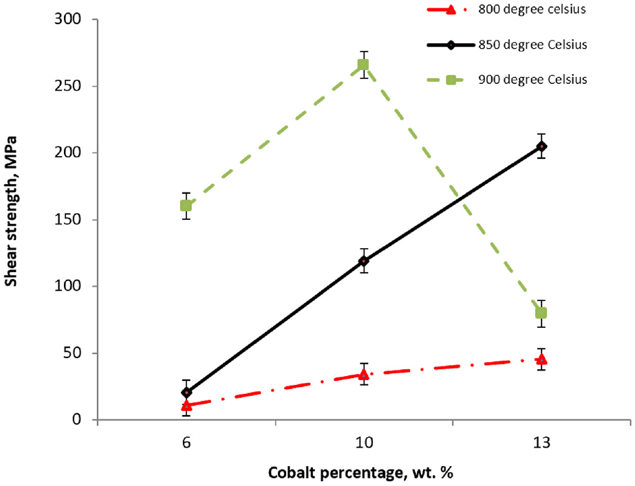
Effect of cobalt percentage at different brazing temperatures on shear strength of the brazed joint.
Fracture behavior observation
After the shear test was done, observations were made based on the fracture behavior of the brazed specimens. Figure 10 shows the fracture behavior observation at different wt% of cobalt and brazing temperatures. At 6% of cobalt and the brazing temperature of 800 °C (Figure 10(a)), all samples failed at the joint between the filler and tungsten carbide with relatively low shear force. Moreover, the wetting was significantly poor. At 6% of cobalt and the brazing temperature 850 °C (Figure 10(b)), wettings improved, and the samples showed better shear strength compared with 800 °C. However, all specimens failed at the filler metal. At 6% of cobalt and the brazing temperature of 900 °C (Figure 10(c)), the samples showed the highest shear strength, but they also showed dissimilar appearance compared with the specimens that brazed at 800 °C and 850 °C.
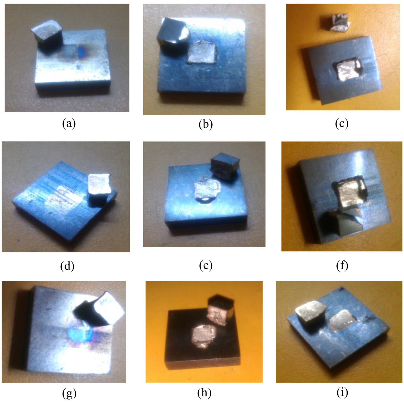
Fracture behavior observation at different brazing temperatures and wt% of cobalt: (a) BT = 800 °C, 6 wt% of cobalt; (b) BT = 850 °C, 6 wt% of cobalt; (c) BT = 900 °C, 6 wt% of cobalt; (d) BT = 800 °C, 10 wt% of cobalt; (e) BT = 850 °C, 10 wt% of cobalt; (f) BT = 900 °C, 10 wt% of cobalt; (g) BT = 800 °C, 13 wt% of cobalt; (h) BT = 850 °C, 13 wt% of cobalt; and (i) BT = 900 °C, 13 wt% of cobalt.
At 10% of cobalt and the brazing temperature of 800 °C (Figure 10(d)), the samples showed poor shear strength and failed at the filler metal. At 10% of cobalt and the brazing temperature of 850 °C (Figure 10(e)), the samples improved in the shear strength value. Two out of three specimens partially failed during the test. The third specimen failed entirely on the steel-based metal, indicating a strong bond in the filler metal. At 10% of cobalt and the brazing temperature of 900 °C (Figure 10(f)), the samples showed a significantly high value in shear strength. Two out of three had broken and failed partially and the other one failed on the tungsten carbide and caused the tungsten to crack, indicating a very strong bond in the filler metal.
At 13% of cobalt and the brazing temperature of 800 °C (Figure 10(g)), the samples showed poor shear strength and insufficient wetting. All specimens failed entirely once the shear force was applied. At 13% of cobalt and the brazing temperature of 850 °C (Figure 10(h)), the shear strength had highly improved. Two out of three specimens failed partially with existing cracks, while the leftover failed completely on the filler. These samples showed good wetting properties. At 13% of cobalt and the brazing temperature of 900 °C (Figure 10(i)), the samples showed a significant decrease in the shear strength. The entire set of the specimens failed completely at the filler metal. These results totally support the results of the shear strength obtained in section “Shear strength results.”
Microhardness
Microhardness test was done on the cross-sectional area of the brazed joint, to investigate the hardness of different sections in the brazing joints at different brazing temperatures and wt% of cobalt. Brazed specimens were prepared, and eight locations in each specimen were tested by the Vickers indenter along the cross section of brazed joint as shown in Figure 8.
Figure 11(a)–(c) shows the effect of cobalt contents on the hardness values at different brazing temperatures. As can be seen in Figure 11, the hardness values of the two substrates at points (1, 2, 3 for tungsten carbide and 6, 7, 8 for steel) are almost the same with little changes at different brazing temperatures. However, the hardness values of the filler material (points 4 and 5) are significantly different due to the elemental migration from/to the two substrates.
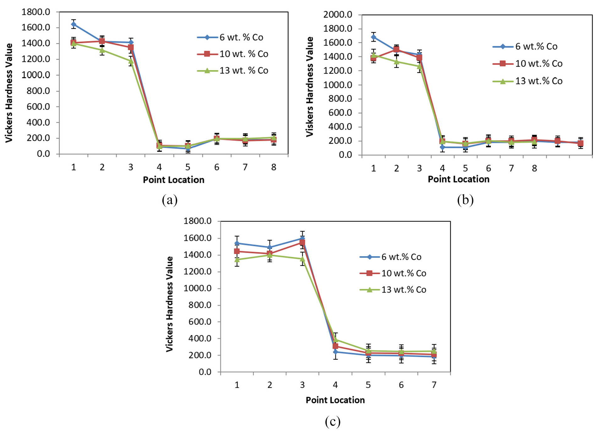
The effect of cobalt content on the hardness values under different brazing temperatures: (a) 800 °C, (b) 850 °C and (c) 900 °C.
At the brazing temperature of 800 °C, the hardness values of points 4 and 5 are smaller than those of the same points in the joint at 850 °C. However, the highest hardness values of the filler material (points 4 and 5) were obtained at the brazing temperature of 900 °C. These behaviors happened due to the increase in the diffusion rate in both the bases and filler materials, when brazing temperature increased from 800 °C to 850 °C to 900 °C, leading to different mechanical and physical properties of the joint and the parent metals. 39 For the brazing conditions at 800 °C, diffusion is almost insignificant. On the other hand, brazing temperature of 850 °C showed better diffusion. However, brazing temperature of 900 °C showed the best diffusion effect compared with other cases.
During the diffusion, elements from filler metal and base metal exchange. Silver or copper from the filler alloy might diffuse into the tungsten carbide, while tungsten, cobalt or carbon might migrate into filler layer. This phenomenon influenced the hardness of the brazed joint, leading to an increase in the hardness values of the filler material (points 4 and 5), as cobalt is much harder than copper. For the specimen C3 (900 °C, 13 wt% cobalt), the higher hard cobalt percentage contents in the tungsten carbide (13 wt%) encouraged higher diffusion rate and more hard-cobalt diffusion into the filler layer at high temperature (900 °C). A significant solid-state diffusion between the basic materials and filler metal was introduced and resulted in the highest hardness (390.1 Vickers Hardness) and gave an inherent brittleness to the joint. This explains why the specimen C3 (900 °C, 13 wt% cobalt) failed at lower load compared with others that had failed at the higher load in Figures 9 and 10. 7 These results will be discussed further with the results of the FESEM and the EDX spectrum analysis in section “Microstructure analysis.”
Microstructure analysis
FESEM analysis
Figure 12 shows the microscopic observation with FESEM for different cobalt contents and brazing temperatures using backscattered electron.
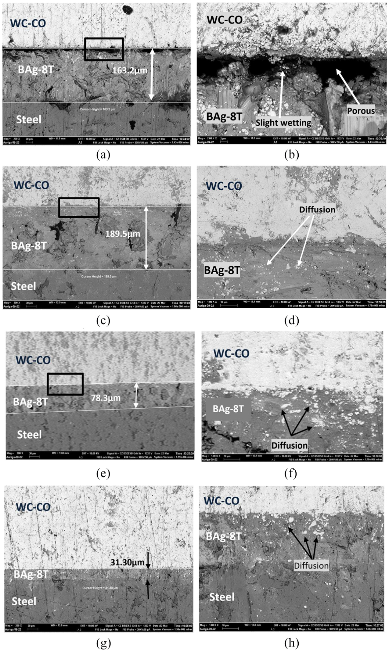
FESEM microscopic observation using backscattered electron: (a) magnification: 200× BT = 800 °C, 6 wt% of cobalt; (b) magnification: 2000× BT = 800 °C, 6 wt% of cobalt; (c) magnification: 200× BT = 850 °C, 10 wt% of cobalt; (d) magnification: 1000× BT = 850 °C, 10 wt% of cobalt; (e) magnification: 200× BT = 900 °C, 10 wt% of cobalt; (f) magnification: 1000× BT = 900 °C, 10 wt% of cobalt; (g) magnification: 200× BT = 900 °C, 13 wt% of cobalt; and (h) magnification: 1000× BT = 900 °C, 13 wt% of cobalt.
Figure 12(a) shows the FESEM image of the cross-sectional area of the brazing joint between tungsten carbide with 6% cobalt and steel, at the brazing temperature of 800 °C. Figure 12(b) shows more details at higher magnification 2000×. As can be seen in Figure 12, the bonding was incomplete, containing cavities that appeared between the tungsten carbide and the filler. Besides, the diffusion is almost insignificant. The reason is that the brazing temperature of 800 °C was low, as it was almost equal to the melting temperature of the filler. At this temperature, the filler is just fully melted, where it has relatively lower wettability compared to 850 °C and 900 °C. Incomplete bonding had only appeared on the surface between filler and tungsten carbide, as the filler needs much higher temperature to activate the surface by the means of titanium content in the filler metal.42,43 However, in the other surface between the filler and steel, the bonding was much better, as the silver-copper-based filler has sufficiently good wetting properties against iron base metal. 41 This explain the previous observation in Figures 9 and 10, where all the brazing joints at 800 °C with different cobalt contents showed low shear strength values and failed on the surface between tungsten carbide and filler metal.
Figure 12(c) shows the FESEM image of the cross-sectional area of the brazing joint between tungsten carbide with 10% cobalt and steel at the brazing temperature of 850 °C. Figure 12(d) shows more details at higher magnification 1000×. As can be seen in Figure 12(c) and (d), the bonding in the brazing joint had totally improved compared with the case performed at the brazing temperature of 800 °C. In addition, there are no cavities lying between the tungsten carbide and filler metal. The filler thickness increased to 189.5 µm because of the good wettability and capillary occurring between the tungsten carbide and the filler, leading to higher diffusion rate. This also explains the previous observation in Figures 9 and 10, where all brazing joints at 850 °C with different cobalt contents showed higher shear strength values compared with the cases performed at 800 °C. All these samples (850 °C) had failed on the filler matter rather than on the surface between tungsten carbide and filler metal, indicating higher bonding strength between the filler and base materials.
Figure 12(e) shows the FESEM image of the cross-sectional area of the brazing joint between tungsten carbide with 10% cobalt and steel at the brazing temperature of 900 °C. Figure 12(f) shows more details at higher magnification 1000×. As can be seen in Figure 12(e) and (f), and Figures 9 and 10, the bonding and the shear strength in the brazing joint were the best, compared with the cases performed at lower brazing temperatures (800 °C and 850 °C). However, the filler thickness decreased to 78.3 µm. This happened because of the high wettability and capillary occurring at higher brazing temperature (900 °C), leading to a much higher diffusion rate taking place between the filler and the two base materials. Hence, the bonding strength had increased, and the filler thickness was reduced. These samples (10 wt% of cobalt and brazing temperature of 900 °C) showed a significantly high value in shear strength (Figure 9). Two out of three had broken and failed partially and the other one failed on the tungsten carbide, causing the tungsten to crack (Figure 10). This indicates a very high bonding strength between the filler and base materials.
Figure 12(g) shows the FESEM image of the cross-sectional area of the brazing joint between tungsten carbide with 13% cobalt and steel at the brazing temperature of 900 °C. Figure 12(h) shows more details at higher magnification 1000×. As can be seen in Figure 12(g) and (h), the bonding in the brazing joints was very good, compared with all the other cases. However, the filler’s thickness had extremely decreased to 31.30 µm and the shear strength is the lowest at 900 °C (Figure 9). The reason is that at the elevated temperature, the high concentration of cobalt and carbon in tungsten carbide encouraged elemental migration from/to the filler, and hence a significant diffusion happened.36–38 The silver and/or copper from the filler alloy had highly diffused into the tungsten carbide, reducing the thickness of the filler. On the other hand, the exchange between cobalt and copper caused an increase in the hardness and brittleness of the filler (cobalt is much harder and brittle than copper), as can be seen in Figure 11(c) (points 4 and 5).36–38 This phenomenon influenced the shear strength of the brazed joint. This explains why the specimen failed at lower load, compared with other cases (Figure 9).36–38 The entire set of the specimens failed completely in the brittle filler material. This will be discussed further in the next section with the results of EDX spectrum analysis.
EDX
The objective of this test is to investigate the existence of the diffusion between the two base materials and filler metal. The technique used is line elemental mapping, where a massive number of points were taken using EDX technique. Figure 13 shows the EDX elemental line mapping for different cobalt contents and brazing temperatures.
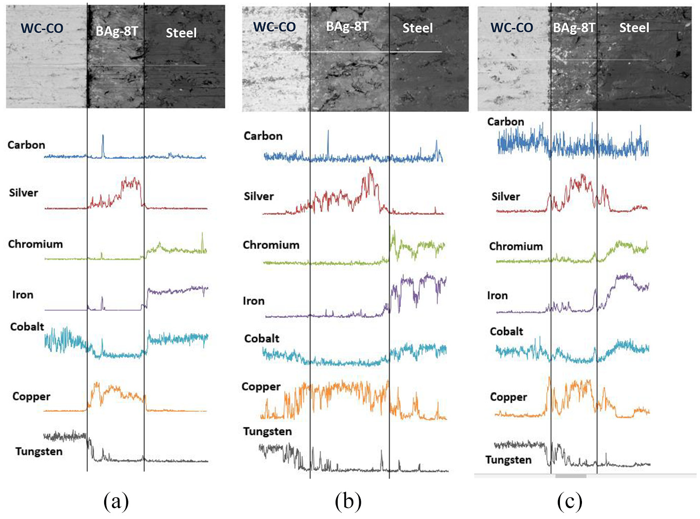
The EDX elemental line mapping: (a) BT = 800 °C, 6 wt% of cobalt; (b) BT = 850 °C, 10 wt% of cobalt; and(c) BT = 900 °C, 10 wt% of cobalt.
As can be seen in Figure 13(a) (6 wt% of cobalt and brazing temperature of 800 °C), the line mapping was done on a location where tungsten carbide is bonded to the filler metal. Although the brazing temperature of 800 °C is relatively low compared to the others, there is a tendency to produce a good brazing joint. Focusing on the cobalt and tungsten, the diffusion for these elements exists. Although the wetting and capillary effects might be poor for this level of temperature, extending the time might improve the wettability of the brazed joint. However, since (BAg-8T) is a mixed-type brazing alloy (eutectic and titanium), extra care while extending the brazing time is required, as the brazing filler may face liquation. 35 In Figure 13(b) (10 wt% of cobalt and brazing temperature of 850 °C), the diffusion is greater than that of 800 °C. Silver, iron, cobalt, tungsten and copper undergo diffusion process. In Figure 13(c) (10 wt% of cobalt and brazing temperature of 900 °C), it is clearly seen that the carbon, silver, chromium, iron, cobalt, copper and tungsten elements undergo diffusion to the adjacent interlayer, producing excellent quality brazing joint. These results are totally supported by the results of the EDX spectrum analysis shown in Figure 14. As can be seen in Figure 14(a)–(c), at elevated temperature, the higher wt% of cobalt encouraged higher diffusion rates to take place between the filler and the two base materials. The silver and copper from the filler alloy are highly diffused into the tungsten carbide. On the other side, hard (Co), (W), (Cr) and (Fe) are highly diffused into the filler metal. The exchange between these elements in the filler and the two base materials causes an increase in the hardness value of the filler metal. These results totally support the previous findings shown in Figures 9–13.
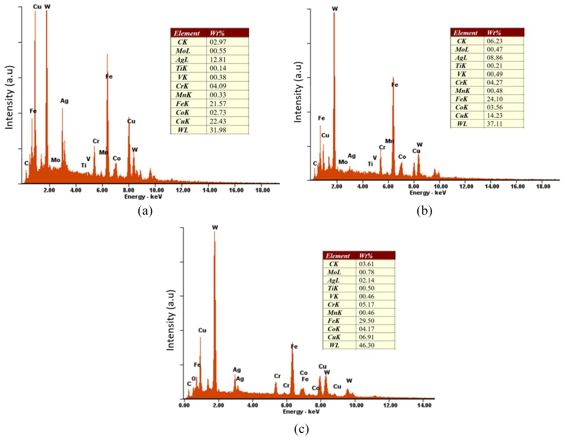
Energy dispersive X-ray spectrum analysis: (a) 6 wt% of cobalt and BT = 800 °C; (b) 10 wt% of cobalt and BT = 850 °C; and (c) 10 wt% of cobalt and BT = 900 °C.
Conclusion
In this research work, a dissimilar brazing of tungsten carbide (WC-Co) and cold work steel utilizing a new near-eutectic silver-copper-based filler material BAg-8T (Ag70Cu28Ti2) is introduced. The investigation was done at different combinations of joining parameters, including the cobalt binder percentage in tungsten carbide (6%, 10% and 13%) and the brazing temperatures (800 °C, 850 °C and 900 °C), where the brazing vacuum condition is constantly set to ×10−4 Pa for every set of specimens. The brazed joints are evaluated using mechanical tests (shear strength and microhardness) and microstructure analysis (FESEM and EDX spectrum analysis).
At any percentage of the cobalt contents in WC-Co, shear strength showed a gradual increase with the increase in the brazing temperature. This behavior happened due to the increase in the diffusion rate in both the base and filler materials at higher temperature. The exchange between cobalt and copper caused an increase in the hardness of filler metal (cobalt is much harder than copper). This also promoted the shear strength. However, for the specimen C3 (900 °C, 13 wt% cobalt), the higher cobalt percentage contents in the tungsten carbide highly encouraged more cobalt diffusion into the filler layer, leading to a significant solid-state diffusion between the basic materials and filler metal, resulting in inherent hardness and brittleness to the joint. This resulted in low shear strength compared with others. The highest shear strength had been obtained in joint B3 (900 °C, 10 wt% cobalt). The diffusion rate was lower than (C3), resulting in a significantly high value in shear strength. Two out of three samples had broken and failed partially, while the remaining sample failed on the tungsten carbide, causing tungsten to crack. This indicates the significant effects of the cobalt contents in WC-Co to determine the best joint performance.
Footnotes
Acknowledgements
The author would like to thank King Fahd University of Petroleum & Minerals (KFUPM) for providing support.
Declaration of conflicting interests
The author(s) declared no potential conflicts of interest with respect to the research, authorship, and/or publication of this article.
Funding
The author(s) disclosed receipt of the following financial support for the research, authorship, and/or publication of this article: This research work is funded by the KFUPM Internal Funded Grant (DSR) Project Code: IN171028.