
Abstract
Mechanical micromachining techniques have gained much popularity in the manufacturing of microcomponents with complex shapes in the past couple of decades. Machining at the microscale poses several challenges such as size effect, which highly influences the material deformation mechanism resulting in a nonlinear variation in specific cutting energy, which accelerates the tool wear. Since micromachining is associated with micro-features, high precision and tight tolerances, the prediction of tool wear in advance is essential. Calibrated tool-wear models are generally used for the prediction of tool wear in the macro machining regime, whereas the applicability of these tool-wear models in the microscale machining is not explored much in the past. In the present work, Usui tool-wear model and worn tool geometry–based Malakizadi model are calibrated for the tool flank wear prediction during micro turning of Ti-6Al-4V alloy, using a hybrid approach involving both finite element simulations and cutting experiments. The validation experiments show that both the models can satisfactorily predict the tool-wear rate during micro turning with a percentage error of less than 15%. Results indicate that the worn tool geometry–based tool-wear model outperforms the conventional Usui model as it incorporates the instantaneous tool geometry, which also makes it suitable for different tool geometries.
Introduction
For the past couple of decades, miniaturization has been one of the key requirements for industries such as biomedical, aerospace and electronics. Mechanical micromachining is preferred over the traditional lithographic methods for manufacturing microcomponents, to overcome the limitations imposed by the material type and geometric complexities of the microcomponents. 1 Micromachining is generally defined as the machining of parts or features of size ranging from 1 to 500 μm. 2 Micro turning is one of the mechanical micromachining techniques for the production of three-dimensional (3D) structures such as micro pins, micro shafts and tools for electro-discharge machining (EDM) process, by employing cutting inserts with micro-features for material removal.3–5 However, during micromachining, factors like edge radius effect, minimum uncut chip thickness effect, ploughing mechanism and so on influence the material removal mechanism resulting in changes in the machining forces, chip morphology, specific cutting energy, surface finish, and so on.6–8 In addition, the machining of superalloys like Ti-6Al-4V, with poor thermal conductivity, spring back effect and chemical affinity to tool materials pose severe challenges in the micro-level resulting in rapid tool wear.9–13
Tool wear in machining is influenced by several factors, which includes tool geometry and material, workpiece material and its physical properties, machining parameters and interface conditions like coolants and so on. The mechanism of tool wear is generally attributed to the individual or combined effect of a number of phenomena like adhesion, abrasion, diffusion and so on. 14 The adhesive and abrasive tool-wear mechanisms are found to be predominant at lower temperatures, while the diffusion mechanism gains significance as the temperature increases. 15 Abrasion with built-up edge and plastic deformation of the cutting edge are found to be dominant in the machining of titanium alloys with different β fractions.16,17 Although studies on the tool-wear behaviour in machining are as old as metal cutting,18,19 one of the earliest efforts to quantify tool life is attributed to the tool life equation by FW Taylor 20 and its modified versions, which relates the tool life with machining parameters. A number of analytical models are proposed by researchers for the tool-wear prediction in different cutting applications and tool–workpiece combinations.21–28 Mechanistic tool-wear rate models which predict the rate of propagation of tool wear, in relation with one or more tool-wear mechanisms such as adhesion, abrasion and diffusion, are also developed by several researchers.29–35 Among them, Takeyama and Murata 29 model and Usui’s et al. 32 tool-wear model gained wide acceptance in the tool-wear prediction for an extensive range of tool-work combinations. Takeyama and Murata’s model considers abrasive as well as diffusive wear mechanisms for predicting the tool flank wear. This model comprises two expressions, one for the mechanical abrasive wear which is related to the cutting velocity and machining length and the second part for the thermal diffusive wear which is related to the cutting temperature. Usui tool-wear model considers adhesive tool-wear mechanism and relates the tool-wear rate with variables such as sliding velocity, contact pressure and interface temperature for predicting the crater wear in carbide tools using a single expression.
With the advanced computational facilities and evolution of finite element simulation, the tool-wear prediction using mechanistic models gained much popularity. Yen et al. 36 and Xie et al. 37 have integrated the Usui’s tool-wear model with two-dimensional (2D) finite element simulation technique for predicting the cutting tool wear, providing an accurate and fast prediction of tool wear. Attanasio et al. 38 performed the 3D finite element simulation to characterize the diffusive tool wear using the Takeyama and Murata model. Attanasio et al. 39 developed a coupled model incorporating abrasive and diffusive tool-wear mechanisms by combining the Usui’s tool-wear model and Takeyama and Murata’s tool-wear model. The coupled model could determine the tool wear accurately, by considering the effects of abrasion, diffusion and adhesion under different cutting conditions. Schulze and Zanger 40 studied the tool wear during the machining of Ti-6Al-4V alloy using finite element method (FEM) technique by incorporating Usui’s tool-wear model into ABAQUS software by means of a user routine. Zanger and Schulze 41 proposed an additive tool-wear rate model by combining the Usui model and Takeyama and Murata model to predict the tool wear during turning of Ti-6Al-4V alloy using uncoated carbide tools. Binder et al. 42 modified Usui’s tool-wear model for the finite element–based simulation of cutting tool wear during turning of AISI 1045 alloy using TiAlN coated and uncoated carbide tools.
While most of the studies utilized the theoretical parameters from the cutting experiment, Yen et al. 36 incorporated the clearance angle of the cutting tool in the tool-wear model. Hosseinkhani and Ng 43 utilized predefined worn tool geometries and proposed a new approach for tool-wear prediction in machining. Malakizadi et al.44,45 incorporated the worn tool geometry into the Usui tool-wear model and simulated the flank wear rate progression during face turning process as well as longitudinal turning process by updating the tool geometry after each simulation cycle. The tool-wear model is calibrated by defining the volume loss in terms of average flank wear width. Hosseinkhani and Ng 46 compared four different models, namely, Takeyama and Murata model, Usui model, Akazawa model and Attanasio model, and proposed a hybrid approach to calibrate the tool-wear models in machining with a minimum number of experiments. Usui tool-wear model is found to be robust as there is no restriction in selecting the magnitude of process parameters during calibration.
For the tool-wear estimation in micromachining, statistical methods such as response surface methodology, fuzzy logic and artificial neural network are reported in the past.47–50 However, the applicability mechanistic tool-wear models in the micromachining regime are less explored. Since the mechanics of machining in the microscale is different from that of macro machining, the tool-wear models need to be calibrated for the micromachining regime. In the current study, Usui’s tool-wear model is calibrated for the prediction of tool-wear rate, during micro turning of Ti-6Al-4V alloy, using finite element simulation and cutting experiments. In addition, a modified tool-wear model, by incorporating the worn tool geometry as proposed by Malakizadi et al., 44 is also calibrated for micro turning applications.
Tool-wear rate model
In the current study, Usui tool-wear model is used for the prediction of tool wear in the micro turning of Ti-6Al-4V due to the highly adhesive nature of titanium alloy. Usui’s et al.32,51 tool-wear rate model considers adhesive tool-wear mechanism and correlates the tool-wear rate with normal stress, interface temperature and sliding velocity as shown in equation (1)
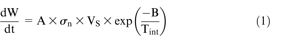
where A and B are model constants, W is wear volume, t is time,
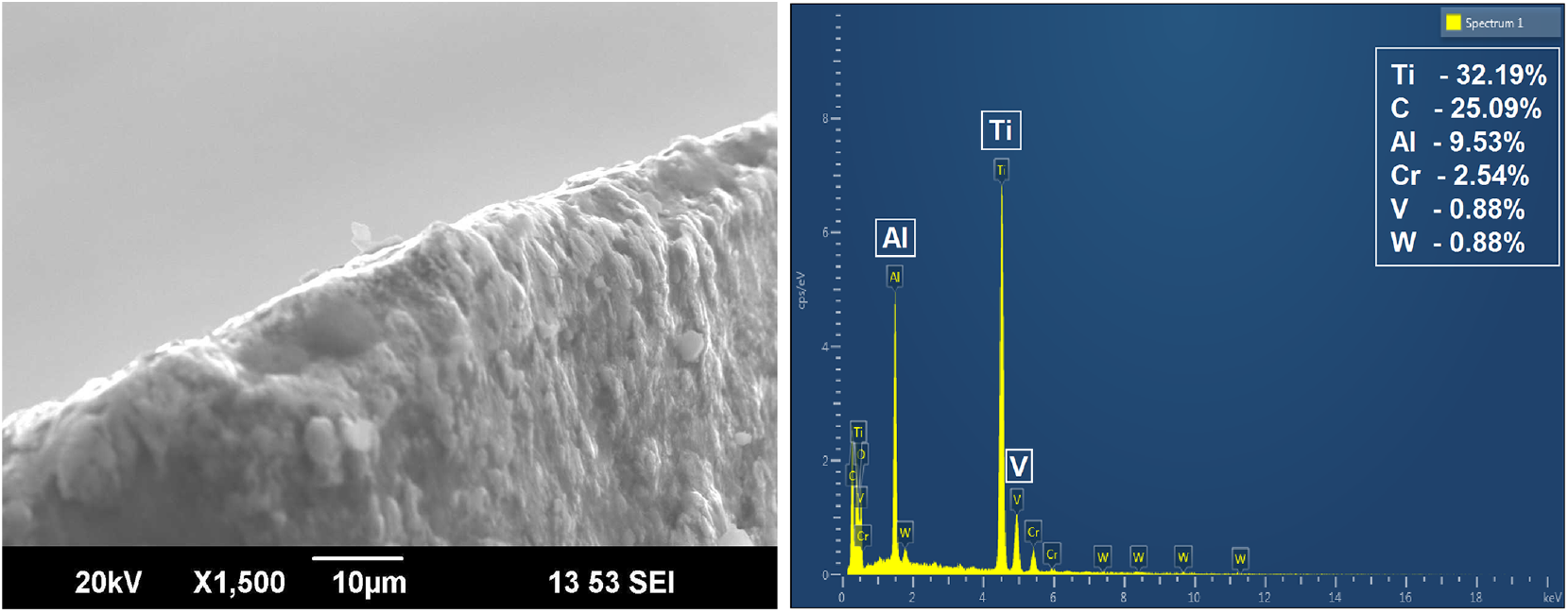
EDAX analysis results and SEM image of the flank face and tool cutting edge.
Preliminary cutting experiments revealed that, in the micro turning process, flank wear is predominant, compared to the crater wear. Hence, the current study is focused on the tool-wear progression on the flank face of the cutting insert. Accordingly, the sliding velocity term
Derivation of the worn tool geometry–based tool-wear model
In the current study, the relation between flank wear width and volume of tool material worn out is found and modified tool-wear model is developed considering the worn tool geometry, inspired from the work done by Malakizadi et al.
45
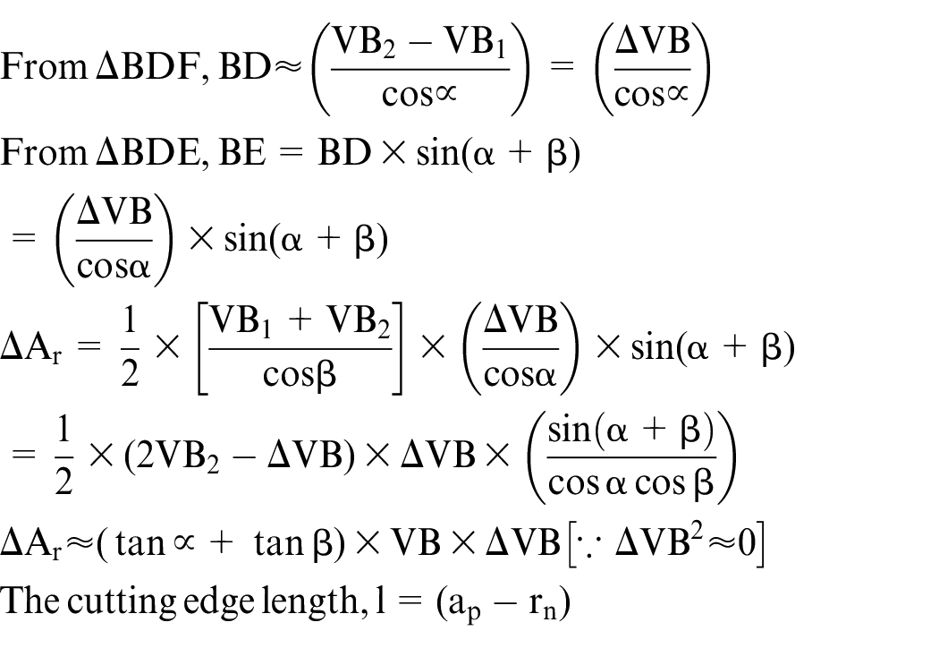
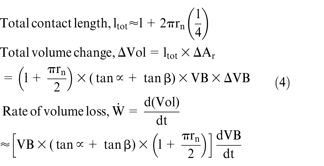
Studies show that during the progression of flank wear, wear land developed will be slightly inclined at an inclination angle (β) and remains constant as cutting progress. The schematic representation of the worn tool geometry during the machining process is shown in Figure 2. The rake angle (γ) and clearance angle (α) are constants for a particular tool, while the inclination angle (β) is obtained by investigating the profile of the cutting edge of the worn tool. The area loss
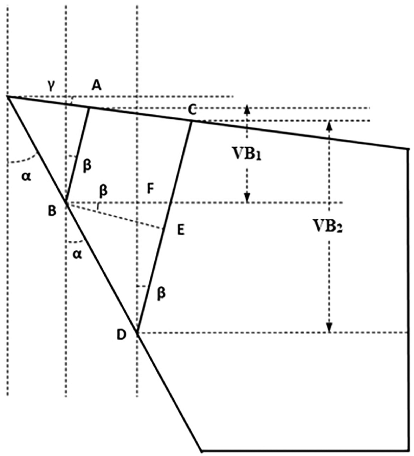
Schematic representation of worn tool geometry with time.
Assuming a constant inclination angle

where
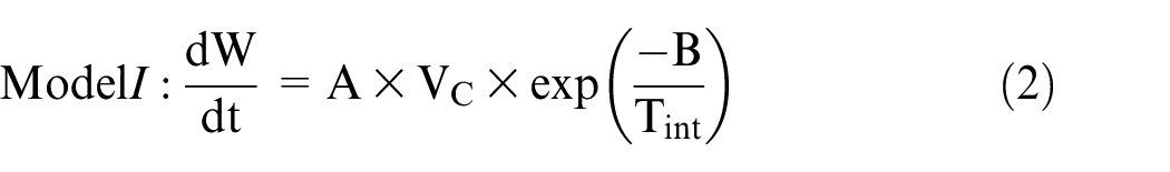
From equations (2) and (4), the worn tool geometry–based tool-wear rate equation, represented as Model II, can be written as
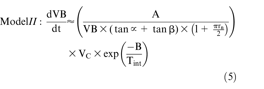
The derived expression for tool-wear rate model using worn tool geometry given in equation (5) is found to be similar to the model proposed by Malakizadi et al. 45 for macro machining. The Model I and Model II are calibrated by employing a hybrid approach using the tool-wear data from the micro turning experiments and temperature data from finite element simulations as proposed by Binder et al. 42
Micro turning experiments
The micro turning experiments are carried out by varying the cutting parameters within the recommended cutting conditions for the tool workpiece combination. The cutting-edge profile is examined at regular intervals, and the corresponding tool wear is measured. Focus variation–based 3D optical profilometer is used for the analysis of the cutting-edge geometry. Finite element simulations for the different cutting conditions are carried out using DEFORM 3D software. Based on the finite element simulation, the interface temperature for each cutting condition is determined. The experimental data and the finite element data are fed to the tool-wear model, and the model constants are calibrated using regression analysis. The calibrated model constants are then validated using random cutting experiments.
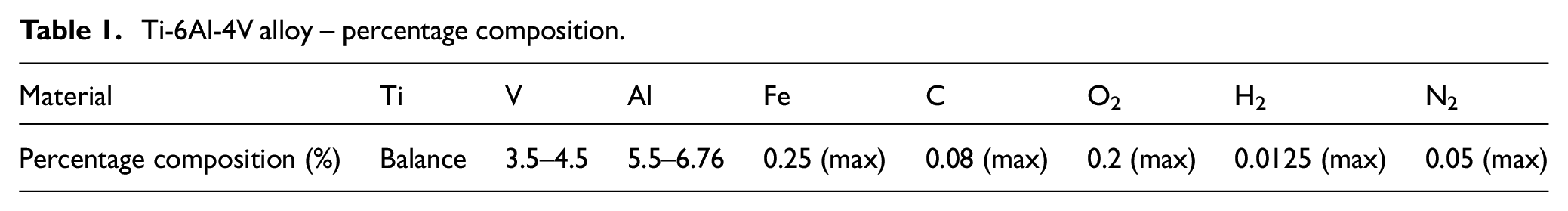
Micro turning experiments are carried out on a 3 axis multipurpose micromachining centre (DT110-MIKROTOOLS). The setup for micro turning experiments is shown in Figure 3. Ti-6Al-4V alloy rods with 6.4-mm diameter are used as the workpiece material. The composition of Ti-6Al-4V alloy is given in Table 1.
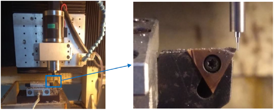
Experimental setup for micro turning.
Ti-6Al-4V alloy – percentage composition.
Coated tungsten carbide cutting inserts (SUMITOMO – TCGT090201) with alternate nanolayers of TiAlN and AlCrN are used for the cutting experiments. The TiAlN–AlCrN multilayer coating exhibits superior mechanical properties such as hardness, scratch resistance and Young’s modulus, compared to conventional coatings such as TiAlN, AlCrN and TiN.52,53 The insert is mounted on an STGCR1010-09 – SUMITOMO tool holder. The tool holder has a 7° clearance angle and 90° approach angle. The average cutting-edge radius of the cutting insert is determined using 3D optical profilometer (Alicona InfiniteFocus G5), by scanning and extracting the cutting-edge profile at 100 sections along the cutting edge, and is found to be 3.35 μm as shown in Figure 4.
Edge radius measurement using 3D optical profilometer (Alicona InfiniteFocus G5).
Preliminary cutting experiments are carried out to study the flank wear progression in micro turning. The tool-wear curve is plotted for three different sets of process parameters, considering the low, medium and high values for speed
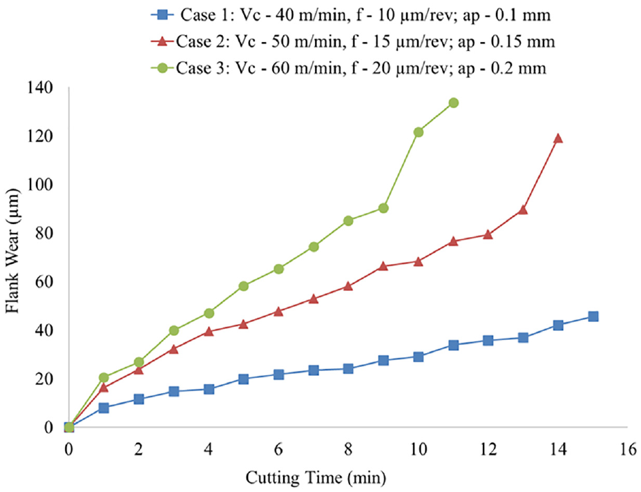
Tool-wear progression under different cutting conditions.
The break-in period is found to be small, and rapid rise in the tool wear is observed after 10 min of cutting for the higher values of cutting parameters (Case 3). Hence, the tool-wear progression from 2 to 7 min, which shows a steady tool-wear progression, is considered for the current study. The average cutting-edge profile gives a clear indication of the condition of the cutting edge and the average volume loss along the cutting edge for a length equivalent to the depth of cut, thereby covering the complete tool–workpiece contact area.
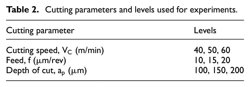
Even though the initial cutting-edge radius was measured to be 3.35 μm, an average edge radius of 7–9 μm is observed, as the machining progresses. Hence, the feed rates for the experiments are selected higher than the average cutting-edge radius, to minimize the size effect. In order to study the tool flank wear, depths of cut greater than and equal to the nose radius of the cutting insert are used for the current study. The cutting speed, feed and depth of cut are varied in three levels as given in Table 2, based on the results obtained from the preliminary experiments and recommended cutting parameters for the tool geometry. The machining operation is interrupted at 2, 4 and 7 min, within the steady-state wear region, and the tool flank wear is measured. A total of 27 cutting experiments are performed considering all the possible combinations of cutting parameters for the calibration of the tool-wear model.
Cutting parameters and levels used for experiments.
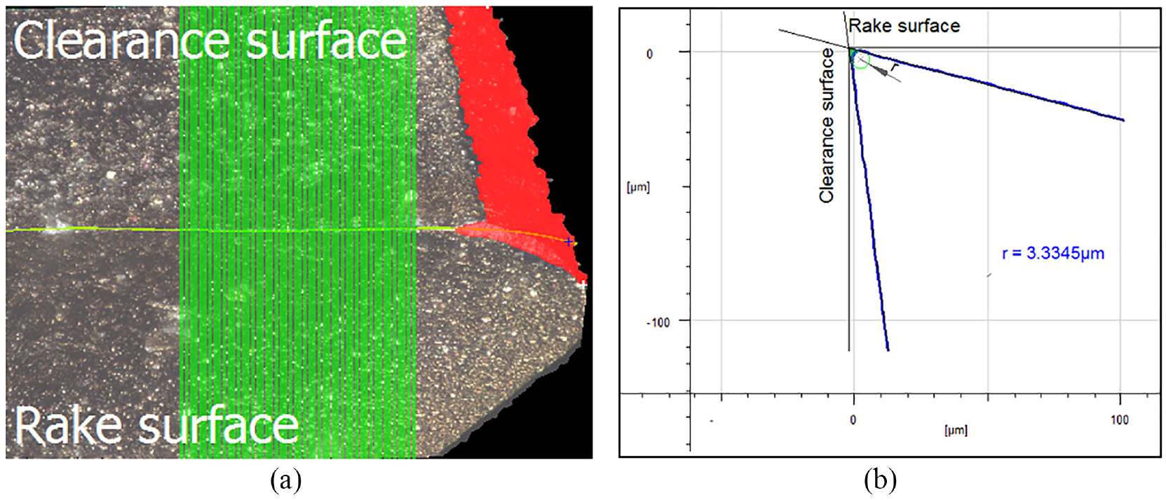
The 2D image of the tool flank observed after 7 min of machining, at a cutting speed of 40 m/min, a feed of 10 μm/rev and depth of cut of 0.2 mm, obtained at 100× optical zoom, using the 3D optical profilometer is shown in Figure 6. The average cutting-edge cross-sectional geometry is obtained by scanning the cutting edge of the worn cutting tool as given in Figure 6. The inclination angle is measured from the average cutting-edge profiles for all the experimental runs. An average inclination angle (β) of 2° is observed for the cutting tool profiles studied.
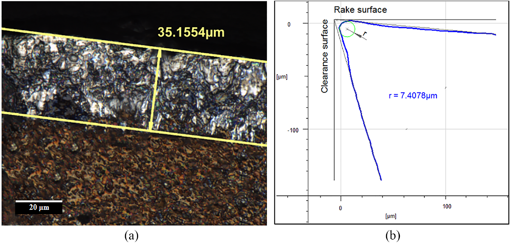
(a) Tool flank wear obtained using 3D optical profilometer at 100× optical zoom. (b) Average cross-sectional profile of the cutting edge after 7 min of machining.
Finite element simulation
In this study, the interface temperature is determined by finite element simulations using DEFORM 3D software which employs Lagrangian formulation for the cutting simulation, and the chip formation is attained by adaptive remeshing. Johnson and Cook (JC) material model,
54
which correlates strain rate, strain and temperature as shown in equation (6), was used for flow stress
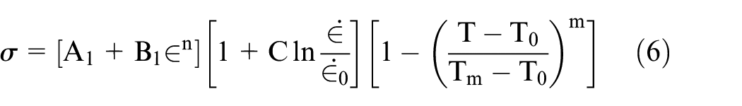
where
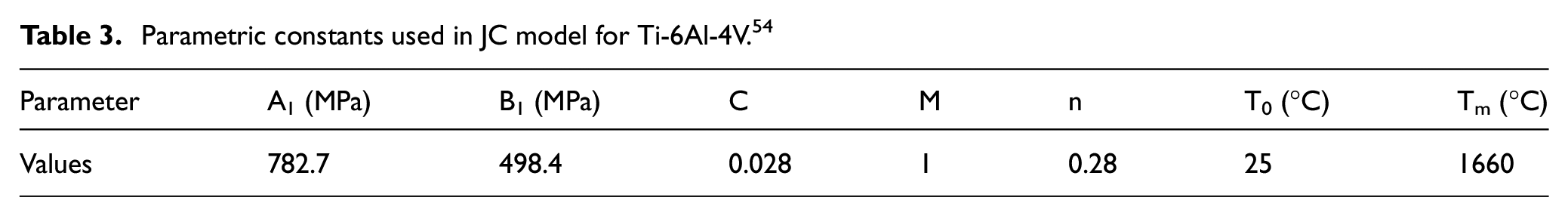
Parametric constants used in JC model for Ti-6Al-4V. 54
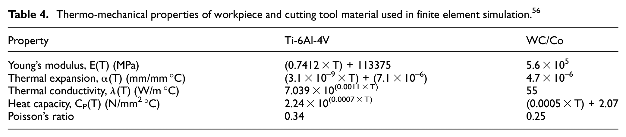
Thermo-mechanical properties of workpiece and cutting tool material used in finite element simulation. 56
Meshing and boundary conditions
Absolute meshing of the workpiece with minimum element size as 25% of the feed is used for the simulation. A finer mesh is provided at the cutting zone compared to the other areas. The boundary conditions are set such that the workpiece motion along x, y and z directions is constrained. The room temperature, convective heat transfer coefficient and the heat conduction coefficient at the tool–workpiece interface is set as 25 °C, 0.02 N/s mm °C and 107 N/s mm °C, respectively. The computer-aided design (CAD) model of the cutting insert is made using SOLIDWORKS software with 15° rake angle, 7° side clearance angle and 3.5 μm as the cutting-edge radius. The CAD model is then imported to DEFORM 3D software. In order to capture the effect of edge radius, a finer mesh is given near the cutting edge of the tool. The optimum number of elements for the cutting tool is determined by conducting a mesh convergence study. A total number of 25,000 tetrahedral elements are used for meshing the cutting tool. Tool material is selected as tungsten carbide and multilayer coating with alternate layers of TiAlN and AlCrN with a total coating thickness of 3 µm is added from the material library.
Friction model
Hybrid friction model available in the DEFORM 3D software is used in the current study. In the hybrid model, shear friction law (
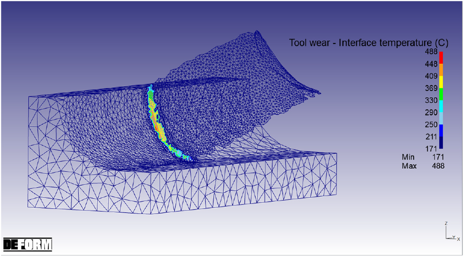
Cutting simulation using DEFORM 3D software.
Calibration of the tool-wear rate models
The tool-wear models proposed in equations (2) and (5) are calibrated using a hybrid approach by incorporating the experimental and finite element simulated values. The equations are rearranged into linear form and are plotted on a semi-logarithmic graph where the model constants can be obtained from the slope and intercept of the trend line. Taking log on both sides and rearranging, equation (2) can be written as
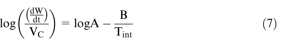
Equation (7) represents a linear relation on a semi-logarithmic graph where
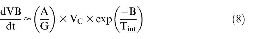
Taking log on both sides and rearranging, equation (8) can be written as
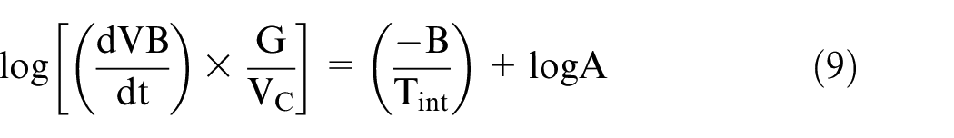
The experimental and simulated data are plotted on a semi-logarithmic graph as shown in Figures 8 and 9. An exponential trendline is plotted to obtain the A and B values for the modified tool-wear model.
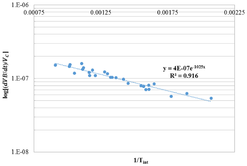
Calibration of Usui tool-wear model by regression analysis.
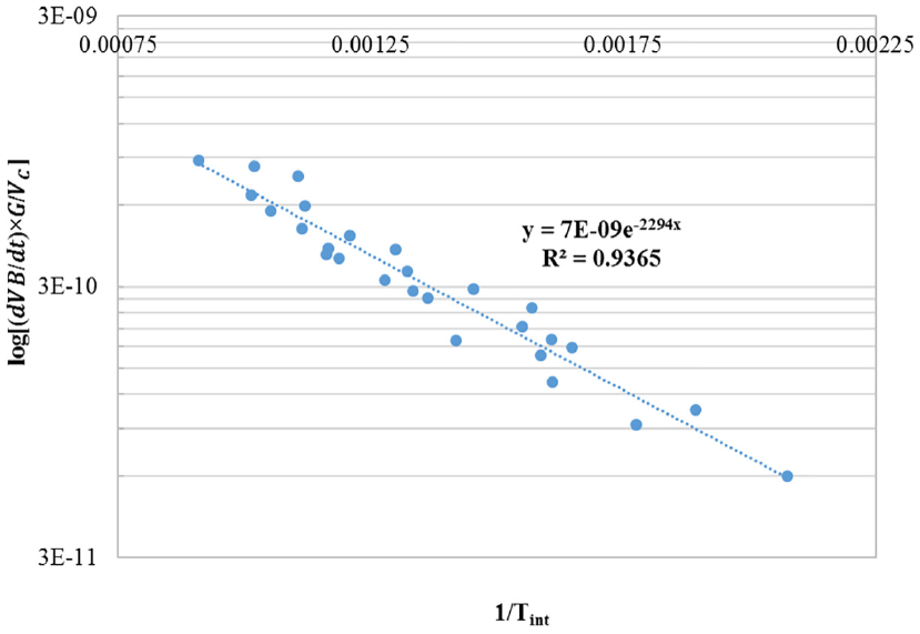
Calibration of worn tool geometry–based tool-wear model by regression analysis.
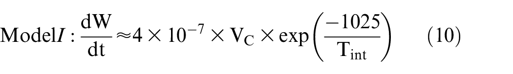
From the regression analysis, the tool-wear constants for Usui tool-wear model are obtained as A = 4 × 10⁻⁷ and B = 1025. Thus, the calibrated Usui tool-wear model can be written as given below
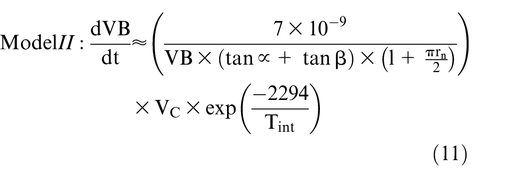
The tool-wear constants for the worn tool geometry–based model are found out as A = 7 × 10⁻⁹ and B = 2294. Thus, the calibrated worn tool geometry–based tool-wear model can be written as given below
Validation experiments
Micro turning experiments to validate the proposed tool-wear models are carried out on Ti-6Al-4V alloy with coated carbide tools, using random machining parameters as given in Table 5. Calibrated Usui tool-wear model (Model I) and the worn tool geometry–based tool-wear model (Model II) are validated using the corresponding tool-wear model constants, obtained using regression analysis. The interface temperature is determined for the validation experiments using finite element simulations. The results of the validation experiments are given in Table 5.
Validation experiments and comparison of results.
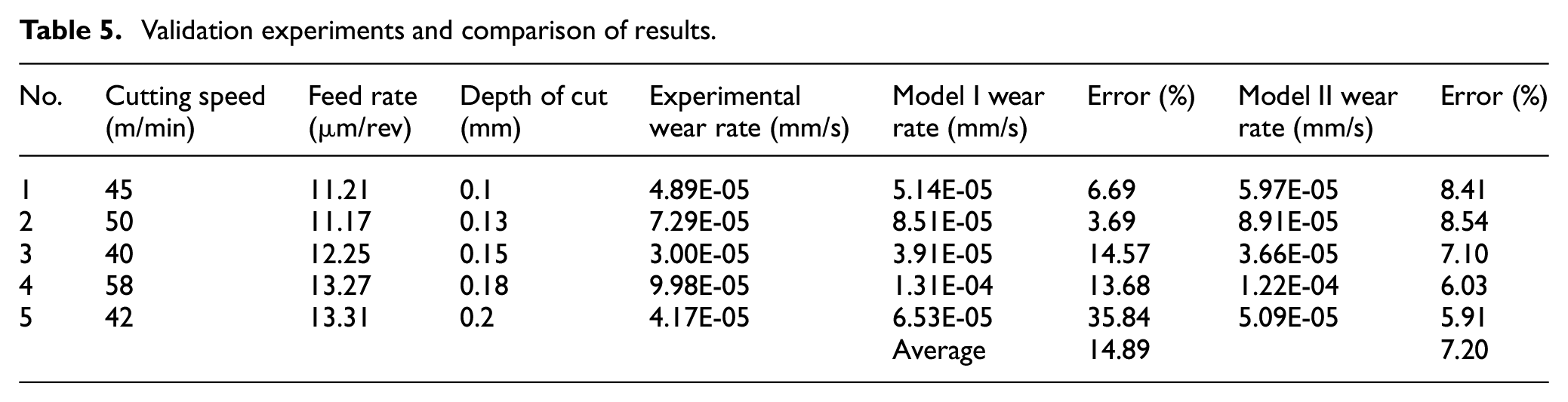
The average percentage error of Model I and Model II is found to be 14.89% and 7.20%, respectively. A comparison of the predicted tool-wear rates using Model I and Model II with the experimentally determined tool-wear rates indicates that both the models are capable of predicting the tool wear during micro turning of Ti-6Al-4V alloy using coated carbide inserts satisfactorily. However, detailed analysis shows that Model II is much more robust in predicting the tool-wear rate compared to Model I. It can be seen from equation (10) that, in case of Usui tool-wear model (Model I), the tool-wear rate prediction depends on cutting velocity and interface temperature, whereas the worn tool geometry–based tool-wear model (Model II) given as equation (11) considers the instantaneous flank wear width and the cutting tool geometry in addition to the cutting velocity and interface temperature.
Since Model I is independent of the cutting tool geometry, the calibrated model constants are applicable for a specific tool geometry. As observed in the preliminary experiments, the cutting-edge radius is varying due to edge chipping and breakage of the built-up edge, which is predominant in the micro turning of Ti-6Al-4V due to adhesion. As a result, accidental tool edge breakage can alter the tool-wear rate. This cannot be predicted using the Model I.
Meanwhile, in Model II, the tool geometry is incorporated in the tool-wear model. This makes the worn tool geometry–based model adequate for a wider range of micro turning applications, with different tool geometries, using the same model constants. This is verified by performing micro turning using inserts with different rake angles. In addition, Model II considers the instantaneous tool wear. Hence, the accidental wear due to edge chipping will be considered in the tool-wear prediction, making it more accurate. Hence, Model II can be used for the prediction of tool-wear rate during micro turning of Ti-6Al-4V alloy using coated carbide tools with different tool geometries.
Conclusion
In the current study, calibration of Usui tool-wear model and modified tool-wear model by incorporating the worn tool geometry into Usui model to predict the tool flank wear rate during the micro turning process are carried out. The volumetric tool-wear value determined by the edge profile analysis of the worn tool is used to define the geometric parameter for the worn tool geometry–based tool-wear rate model. This model incorporates instantaneous flank wear width and inclination angle, in addition to the cutting velocity and the interface temperature for the prediction of the tool-wear rate more precisely. A hybrid procedure, using both experiments and finite element simulation, is used to calibrate both the tool-wear models. The modified models are validated by cutting experiments, and the average percentage error is found to be 7.2% and 14.89% for the worn tool geometry–based model and the conventional Usui tool-wear model, respectively.
Validation experiments show that both conventional and worn tool geometry–based tool-wear models are capable of predicting the tool-wear progression rate during the micro turning of Ti-6Al-4V alloy with coated carbide tools using the calibrated model constants accurately.
The conventional Usui tool-wear model is independent of the tool geometry and instantaneous tool-wear rate. Hence, this model is applicable to a limited set of tool geometries, and it does not consider the accidental tool edge breakage or chipping for tool-wear prediction. This necessitates the calibration of model constants for different tool geometries.
The worn tool geometry–based tool-wear model considers the instantaneous tool geometry, which helps in predicting the modified tool-wear rate more precisely and can be used for different tool geometries effectively without changing the model constants.
Footnotes
Appendix 1
Declaration of conflicting of interests
The author(s) declared no potential conflicts of interest with respect to the research, authorship, and/or publication of this article.
Funding
The author(s) disclosed receipt of the following financial support for the research, authorship, and/or publication of this article: The authors thankfully acknowledge the support of the Department of Science & Technology, Government of India & Centre for Precision Measurements & Nanomechanical Testing, Dept. of Mechanical Engineering, NIT Calicut for providing the facility to conduct this study under ‘Fund for Improvement of Science & Technology’ scheme (No. SR/FST/ETI-388/2015). The authors would also like to thank Machine Tool Lab, Dept. of Mechanical Engineering, IIT Bombay for providing the facility for finite element simulation.