
Abstract
Side milling thin-walled workpiece edges is an indispensible procedure in the continuous process chains for the high-efficiency machining of thin-walled functional parts, for example, the small- and medium-sized compressor blades. In these operation cases, the workpiece vibration is easy to occur due to the poor stiffness of the thin-walled structures, causing defects to the machined surface finish and even the dimensional accuracy of the thin-walled workpiece edges. To this problem, this study proposes the tool inclination method based on the adaption of the cutting force component in the lowest stiffness direction of the thin-walled workpiece, and it aims, first, to guarantee the machined surface finish which is mostly dominated by the workpiece vibrations mainly induced by the relatively high cutting forces and, second, to guarantee the high machining efficiency. The parametric study on the tool inclination angle for side milling the thin-walled workpiece edges was conducted by using the finite element simulations. First, the finite element models were elaborated and validated by the experimental results in terms of the cutting forces. Then, based on a series of finite element simulations, the effects of the tool inclination angle on the cutting forces adaption and its corresponding mechanism, that is, the chip formation variation, were investigated. Simulation results under the given conditions showed that the optimal tool inclination angle for the minimum absolute value of Fn was 26°. At last, the prediction feasibility for the best machined surface finish when side milling the low-stiffness thin-walled workpiece edges at the optimal tool inclination angle was well validated by the experimental results. The proposed tool inclination method with the solid end mill based on the finite element model to improve the machined surface finish is meaningful and feasible for the high-efficiency manufacturing processes of thin-walled workpieces.
Introduction
Research background
Milling of thin-walled workpieces has long been a hot research focus in both academia and industry, concerning the topics of suppression of machining vibrations, improvement of machined surface quality, advances of machining efficiency, and so on. 1 However, current literature mostly focus on the operation of milling large surfaces of the thin-walled structures, because they are generally the functional surfaces of the parts. 2 Oppositely, seldom literature have paid attention to the operation of milling the thin-walled workpiece edges (i.e. the narrow and long surfaces). Indeed, this operation is still quite important especially for the high-efficiency process chains of the complex thin-walled components particularly in the high-end and precise equipment manufacturing industries, for example, the aero industries. In this situation, the machined surface quality is also highly required and therefore deserves much research attention. Here is a practical case of 5-axis finish milling of the compressor blades for better understanding.
Compressor blades are the key components in aeroengines that generally have very high requirements of geometrical precisions and machined surface finish. The top surfaces of the blades are also required to have good surface finish, because they have extreme sensitivities on the aerodynamics performances and even the rubbing forces (the penetration depth can reach up to 80 μm during working) between the compressor blade top surface and the casing. 3 Machining of the blade top surface is generally arranged as the last step in the 5-axis milling process chains (see Figure 1). Before milling the blade airfoils, the rough blade is strongly clamped by the root fixture and head fixture (see Figure 1(a)). Then, the blade rotates slowly and the tool feeds along the spiral routines covering the airfoils to finish milling this feature (see Figure 1(b)). After that, it comes to the last step of the 5-axis milling process chains, where the blade is just clamped by the root fixture as a cantilever, and the tool moves to side mill the narrow and long top surface (see Figure 1(c)). In this operation case, the tool feeds very slowly in order to avoid causing the vibration marks to the machined surface due to the high tool feed rates (see Figure 1(d)). However, the application of slow tool feeding to guarantee the machined surface finish, generally characterized by surface roughness, has evidently prevented the improvement of machining efficiency, which is definitely a significant limitation for mass production of blades.
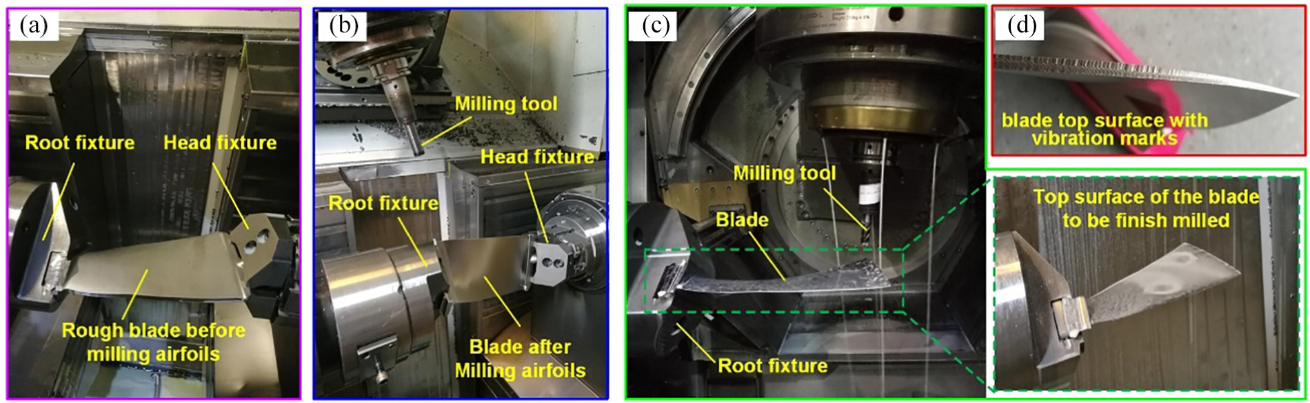
Part of 5-axis process chains for the compressor blade: (a) clamping of the rough blade, (b) finish milling blade airfoils, (c) finish milling the blade top surface, and (d) the blade top surface with vibration marks under high feed rate milling.
The given case above tells us that side milling thin-walled workpiece edges is an indispensable procedure in the continuous process chains for the high-efficiency machining of thin-walled functional parts. In operation cases like this, the workpiece vibration is easy to occur due to the poor stiffness of the thin-walled structures, causing defects to the machined surface finish and even the dimensional accuracy of the thin-walled workpiece edges. To improve machined surface finish during milling the thin-walled workpieces, vibration suppression has been regarded as the primary and effective solution in literature, and many methods have been proposed by researchers.
Relevant research review
First, many researches have attempted to optimize the machining parameters so that the tool–workpiece interaction can be minimized, and the machined surface finish can be guaranteed. Bediaga et al. 4 and Zhu and colleagues 5 proposed the finite element (FE) methods to estimate the natural frequencies of the machine tool–workpiece–cutter system, based on which, the appropriate spindle speeds were suggested to minimize the resonance vibrations. Instead of the FE methods, Guo et al. 6 analytically established a dynamic model of the thin-walled milling process and obtained the multi-mode stability lobes, based on which the optimum spindle speed for the qualified surface was provided. Except for the spindle speed, the tool feed rate was also optimized by Koike et al. 7 based on the minimum workpiece displacement at the cutting points. The machined surface roughness was found to be improved. Quintana et al. 8 focused on the optimization of cutting depths and found that, when the cutting depth was smaller than a threshold value, the machining vibrations could be avoided to a large extent.
Second, the design and employment of appropriate fixtures has been found to be another vibration suppression way. Aoyama et al. 9 demonstrated a new fixture device that was able to support the thin and compliant workpieces securely and minimized the deformation due to the machining forces; therefore, the machined surface finish was improved. Another device pre-tensioned by torsion springs was described by Kolluru and Axinte. 10 By this device, the dynamic characteristics of the structure were kept constant and therefore the better controllability of machined surface dimensions could be obtained. Qin et al. 11 optimized the fixture structures used for machining the thin-walled workpiece based on the clamping deformation characteristics of the workpiece to be machined, and finally designed the fixture layout for the thin workpiece.
Third, apart from the optimization of cutting parameters and fixture structures mentioned above, some passive and active damping methods have also been applied to stabilize the machining process. Shi et al. 12 presented a constrained layer damper based on the established dynamic model for the thin-walled milling system. Interestingly, Paul et al. 13 used a particles damper to mitigate the low-rigidity tool vibrations, because it was found that the particles damper was effective to dissipate energy by the friction between the particles when the damper vibrated.
However, most of the aforementioned methods have their intrinsic drawbacks. For the studies on the special fixtures or additional dampers, the additional and complex setups are needed while a multitude of preliminary trials are essential to iteratively adjust the setup performances, largely increasing the machining cost and production cycle. On the contrary, the other studies on the machining parameter optimization are much cost-efficient. However, most of them have focused, as mentioned in the first paragraph, on the operation of milling large surfaces of the thin-walled structures, as they are relatively more common in the economic industries. Very few of them have studied the optimal parameters selection for the special cases of milling thin-walled workpiece edges. In these cases, in comparison with the adjustments of the feed rates, spindle speeds, cutting depths or even the tool geometrical parameters, the adaption of tool inclination angles (i.e. the angle between the tool axis and the tool feed direction) for mitigating the workpiece vibration and improving the machined surface finish seems to be more convenient, lower cost and easier to be accepted by industries, which could furthermore guarantee the high machining efficiency.
In fact, there is a high possibility that the machined surface finish of thin-walled workpiece edges can be improved via adjusting the tool inclination angle, because: (1) when side milling the thin-walled workpiece edges, the machined surface finish was mainly affected by the deformation and vibration, 7 particularly along the perpendicular direction of the workpiece edge as the thin-walled workpiece stiffness is much weaker along this direction, (2) whether the vibration or the deformation is originally induced by the relatively high milling force component (denoted as Fn) along this direction, and (3) Fn can be largely influenced by the tool inclination angle (denoted as θ). 14
Based on the above statements, this article proposes the tool inclination method for side milling the thin-walled workpiece edges and attempts to adapt the cutting force component in the lowest stiffness direction of the thin-walled workpieces, in order to guarantee the machined surface finish mostly dominated by the force-induced workpiece vibrations. The parametric study on the tool inclination angle for side milling the thin-walled workpiece edges was conducted by using the FE simulations. First, the FE models is elaborated with details and experimentally validated in terms of the cutting forces. Then, based on a series of FE simulations, the effects of the tool inclination angle on the cutting forces adaption and its corresponding mechanism, that is, the chip formation variation are investigated. At last, based on the experimental results, the machined surface finish of the low-stiffness thin-walled workpiece edge is improved using the suggested tool inclination angle by the FE model. Therefore, the proposed tool inclination method based on the FE model to improve the machined surface finish is meaningful and feasible for the practical manufacturing processes of thin-walled workpieces.
The FE-based methodology
3D geometries of the tool and workpiece
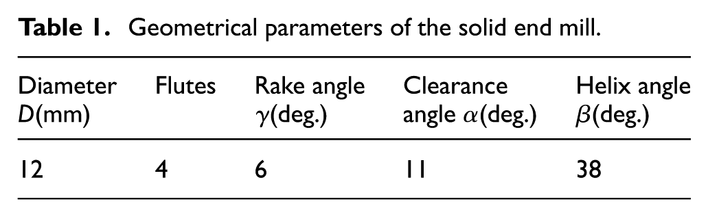
Both the milling tool and the workpiece geometries were modeled by the 3D drawing software Unigraphics NX 9.0 and then imported into the FE simulation system DEFORM-3DTM in the file format of Standard Template Library (STL) (see Figure 2). The geometrical parameters of the solid end mill were given in Table 1, the workpiece thickness was 2 mm, and all of these parameters were the same as those applied in the following experiments in the “Experimental details” section. It is worth noting that the length and width of the workpiece were 30 mm and 20 mm, respectively, which were different from the corresponding experimental setups but would not influence the focus of the cutting forces to be investigated, as the FE simulation only computes the plastic deformation of materials without consideration of machining dynamics.
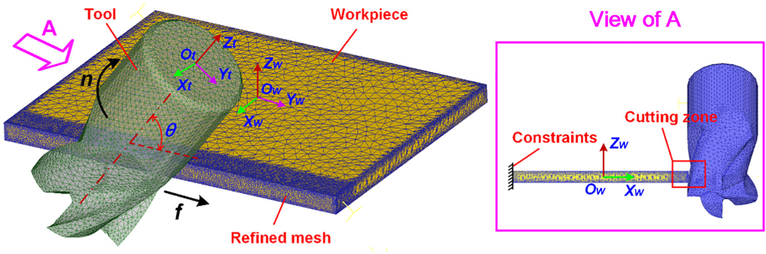
3D finite element model for milling the thin-walled workpiece edge.
Geometrical parameters of the solid end mill.
Material properties and constitutive model
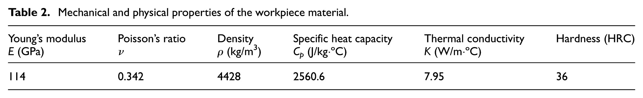
The material of the workpiece was Ti-6Al-4V. The material of the solid end mill was uncoated 15% cobalt-based cemented carbide. Both the workpiece and the tool materials in simulation were the same as those to be used in the following experiments. The mechanical and physical properties of the workpiece having significant effects on the cutting process were listed in Table 2.
Mechanical and physical properties of the workpiece material.
To better illustrate the thermo-mechanically coupled cutting process, the Johnson–Cook (JC) constitutive model established by Johnson and Cook was used in this simulation. This model has considered the effects of large strains, high strain rates, and the rapid temperature rise on the mechanical properties of materials. Due to its admirable application at extreme conditions of the cutting process, the model has been widely used by many researchers,15–17 which is expressed as

where ε is the equivalent plastic strain,
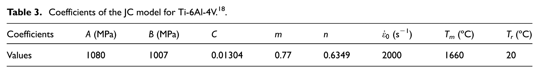
Coefficients of the JC model for Ti-6Al-4V. 18 .
Mesh
In this investigation, the tool was regarded as a rigid body. It was necessary to apply mesh to the tool for computing the heat conduction, because some of the heat generated in the cutting process would be conducted into the tool body 16 and therefore make a significant influence on the temperature distribution in the cutting zone. This variation would affect the flow stress of the material and finally affect the resultant cutting forces. As for the workpiece, it was regarded as the plastic type. To improve the simulation accuracy, the automatic remeshing method was applied to the vicinity area of the machining surface of the workpiece, where the mesh size ratio was 0.1 in comparison with that in the other areas. The total numbers of the elements used for the tool and the workpiece were 38,693 and 167,000, with the minimum element edge length of 0.12 mm and 0.04 mm, respectively. Besides, all these elements applied for both the workpiece and the tool were of the tetrahedral type with four nodes and 12 degrees of freedom, because the tetrahedral mesh had an excellent ability for continuously adaptive remeshing.
Boundary constraints
In this FE simulation system, the cutting process was carried out with the effects of vibrations neglected. Therefore, the influence of vibrations on the cutting forces to be predicted in this article would be avoided. In addition, the tool wear was also assumed to be reasonably neglected since the new and intact milling tools were applied to each trial, and no cutting fluids were used in both the FE analysis and the following experimental trials.
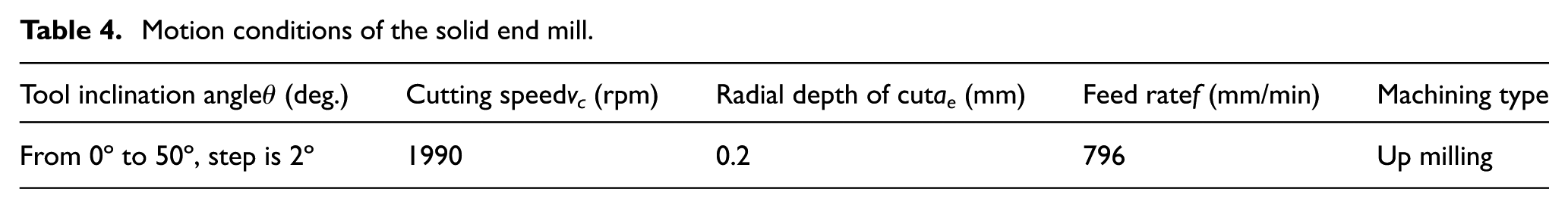
As the relative position setup of the tool and the workpiece showed (see Figure 2), the workpiece was stationary, and all the nodes opposite to the machined surface were constrained to be unmovable, just playing a similar role in clamping the workpiece. On the contrary, the solid end mill was movable along the thin workpiece edge under the motion conditions listed in Table 4. The simulations were separately conducted under different tool inclination angles from 0° to 50° with a step of 2°, while other variables were kept constant, in order to investigate the effects of the tool inclination angles on the variations of cutting forces. It might be noted that the investigated range of the inclination angle from 0° to 50° was suitable for most of the practical machining solutions.
Motion conditions of the solid end mill.
As is known, the friction and heat transfer exist in the contact surfaces between the tool and the chip, as well as between the tool and the workpiece. They could play an important role in the metal cutting operations. According to the similar study on simulating the milling process of Ti-6Al-4V, 15 the constant Coulomb friction value of 0.65, the heat transfer coefficient of 1.5 N/(sec·mm·ºC) between the tool and workpiece, and the energy transfer ratio of 0.9 from mechanical deformation energy to heat were applied in this investigation. The high energy transfer ratio indicated that much more heat would be generated by the shearing stress in the primary deformation zone than that by the rubbing stress on the contact surfaces between the tool and workpiece. The environment temperature is set to be 20 ºC, and the heat convection coefficient is 0.02 N/(sec·mm·ºC).
Material damage criteria
The material damage criteria are usually utilized as the chip separation criterion in the cutting process simulation. In this investigation, the most widely used damage criterion proposed by Johnson and Cook 19 was used, because it had considered all the effects of the strains, strain rates, and temperatures on the deformation behavior of the materials. The criterion can be expressed as

where d1∼d5 are the constant parameters, p is the hydrostatic pressure, q is the Mises stress,
Parameters of the JC damage criteria for Ti-6Al-4V. 15 .

Post process of cutting forces
The cutting forces obtained from the post processor of the simulation system were in the tool coordinate system Ot-XtYtZt. For the purpose of this investigation, it is necessary to transform the forces into the workpiece coordinate system Ow-Xw Y w Zw by
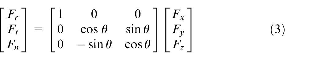
where θ is the tool inclination angle, Fr, Ft, Fn are the cutting forces along Xw-, Yw-, and Zw-axis, respectively, Fx, Fy, Fz are the cutting forces along Xt-, Yt-, and Zt-axis, respectively.
Experimental details
The parametric study purpose of this article is first to obtain the optimal tool inclination angle at the minimum Fn without the influence of vibrations, and then to apply this angle for side milling the low-stiffness thin-walled workpiece edges in order to improve the workpiece vibration suppression performance and finally the machined surface finish. For this purpose, the experiments were planned in this section.
One note here is that, when milling the low-stiffness thin workpiece edge, the workpiece vibrations would affect the cutting forces severely and cause lots of noise signals into them, which would make it hard to post process the forces data. Therefore, two experimental configurations were designed in this article. One of them was for the cutting forces testing trials that used a short plate with a cantilever length of 8 mm (see Figure 3(b)), in order to provide cutting forces without the influence of workpiece vibrations and then to validate the established FE models (where the forces were also without influence of vibrations). In the configuration of cutting forces validation trials, the new and intact milling tools were applied to each trial, so the tool wear can be ignored. The configuration is reasonable because due to the very short protrusion of the workpiece and the strong chucking effect, the influence of vibrations on the cutting forces could be small enough to be ignored. For this experimental configuration, the trials were conducted using the same process parameters as listed in Table 4 except that the tool inclination angle is 0°, 10°, 20°, 30°, 40°, and 50°, so as to reduce the test workload but provide considerable experimental data for supporting the purpose of this study. The other configuration was for the machined surface finish testing trials that used a long plate with a cantilever length of 80 mm (see Figure 3(c)), in order to validate the improvement of the machined surface finish at the suggested tool inclination angle by the FE model during side milling the low-stiffness workpiece edges.
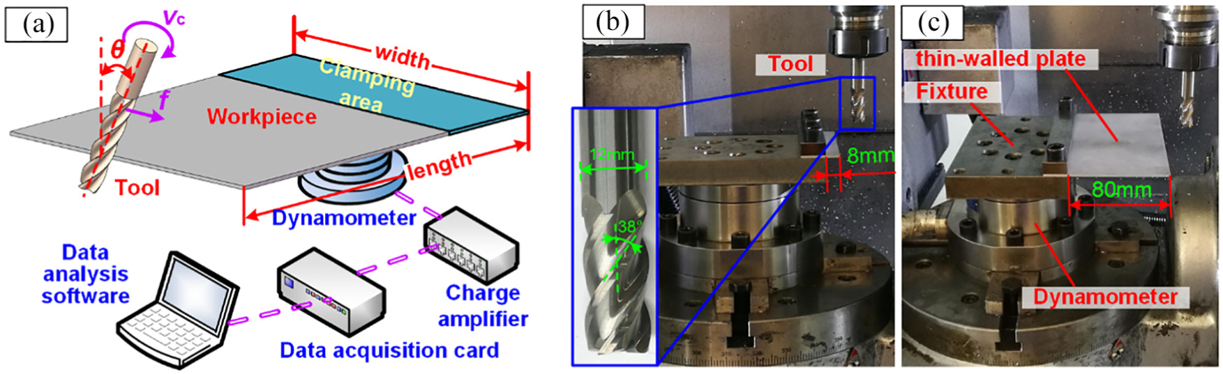
Experimental setup: (a) the scheme showing the tool–work relation, (b) the configuration for the cutting forces testing trials, and (c) the configuration for the machined surface finish testing trials.
All the trials were performed on the 5-axis milling center (Hurco VMX-42) without any coolants applied. An uncoated cemented carbide tool having the same geometrical parameters as that in the aforementioned FE model was used in the present study. As the scheme of the tool–workpiece relation illustrates (see Figure 3(a)), the dynamometer (Kistler 9272) with a sampling frequency of 5 kHz was fixed at the bottom of the thin Ti-6Al-4V workpiece and was connected with a four-channel charge amplifier (Kistler 5017B). Details of the chemical composition and physical properties of the studied workpiece material are listed in Table 6 and Table 3, respectively. It is worth noting that the experimental procedures and process parameters in the machined surface finish testing trials were all the same as those in the cutting forces testing trials, except that the cutting forces were unnecessary to collect again.
Chemical compositions of Ti-6Al-4V (wt. %).

In the machined surface finish testing trials, the vibration amplitude of the workpiece edge was measured by the laser displacement sensor (CD5 L-25, resolution 0.02 μm, measurement range 2 mm) (see Figure 4(a)). The machined surface roughness on the middle of the thin-walled workpiece edge was measured with a portable roughness tester (Mitutoyo SJ-210, sampling points 8, step length 0.8 mm) (see Figure 4(b)), just after each trial was completed. Also, the machined surface topographies were taken to be observed by the optical microscope (Keyence VHX-600).
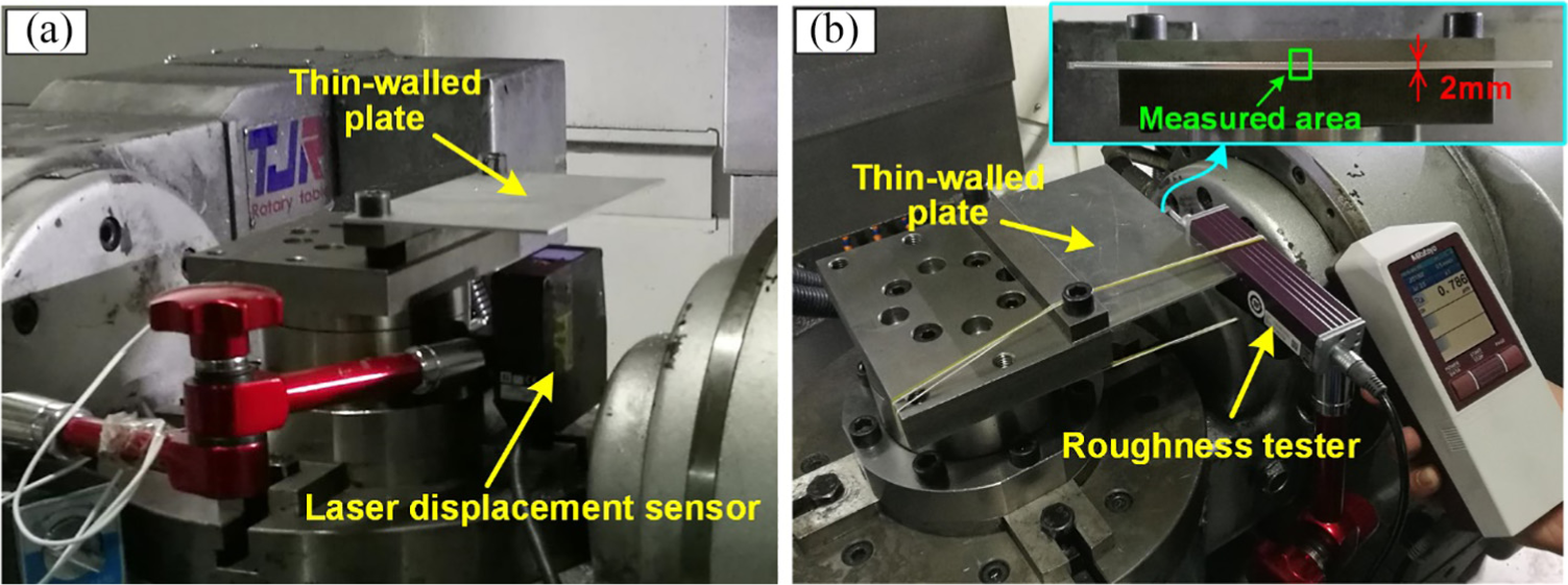
Measurement of (a) the vibration displacement amplitudes and (b) the machined surface roughness.
Validation of the established FE model
This section aims to validate the established FE model by comparing the simulated cutting forces with the experimental ones gotten from the cutting forces testing trials. The measured dynamic vibration displacement of the short plate (see Figure 5) shows that the vibration amplitude of the plate is generally smaller than 2 μm; therefore, the effect of the workpiece vibration on cutting forces can be reasonably neglected. The comparisons of the 3D time-varying cutting force components obtained from simulations and experiments at the tool inclination angle of 20° and 50° are given as the example (see Figures 6 and 7). It is clear that the predicted and measured force curves in all the three directions coincide well. The variations of forces are periodical due to the periodical engagements of the tool cutting edges with the workpiece. At the relatively small cut width in this investigation, each engagement period is followed by a cut-free period. Besides, during the engagements, all the three force components first increase and then decrease almost linearly. In order to explain the similarities of the predicted and experimental results quantitatively, the comparison of the maximum/minimum values (see Figure 8) and that of the average values (i.e. the averages of the measured time-discretized force values and the predicted step-discretized force values, see Figure 9) of Fr, Ft, and Fn at different inclination angles are presented.
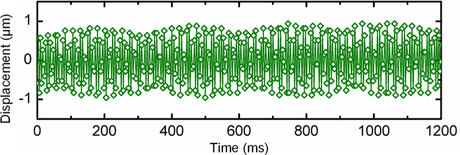
Instantaneous vibration displacement of the short plate.
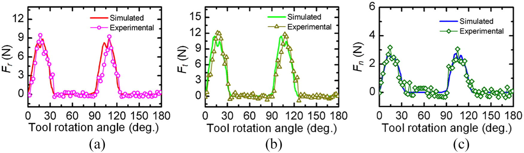
Comparison of the predicted and experimental time-varying cutting forces at θ = 20°: (a) Fr, (b) Ft, and (c) Fn.
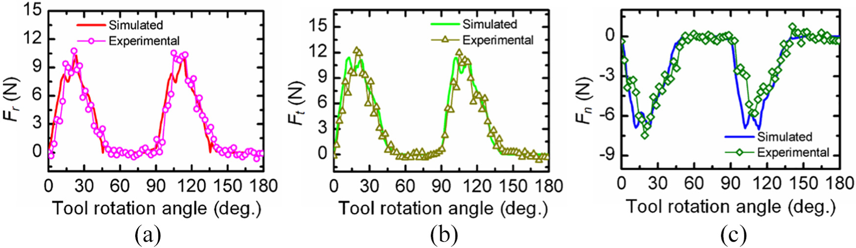
Comparison of the predicted and experimental time-varying cutting forces at θ = 50°: (a) Fr, (b) Ft, and (c) Fn.
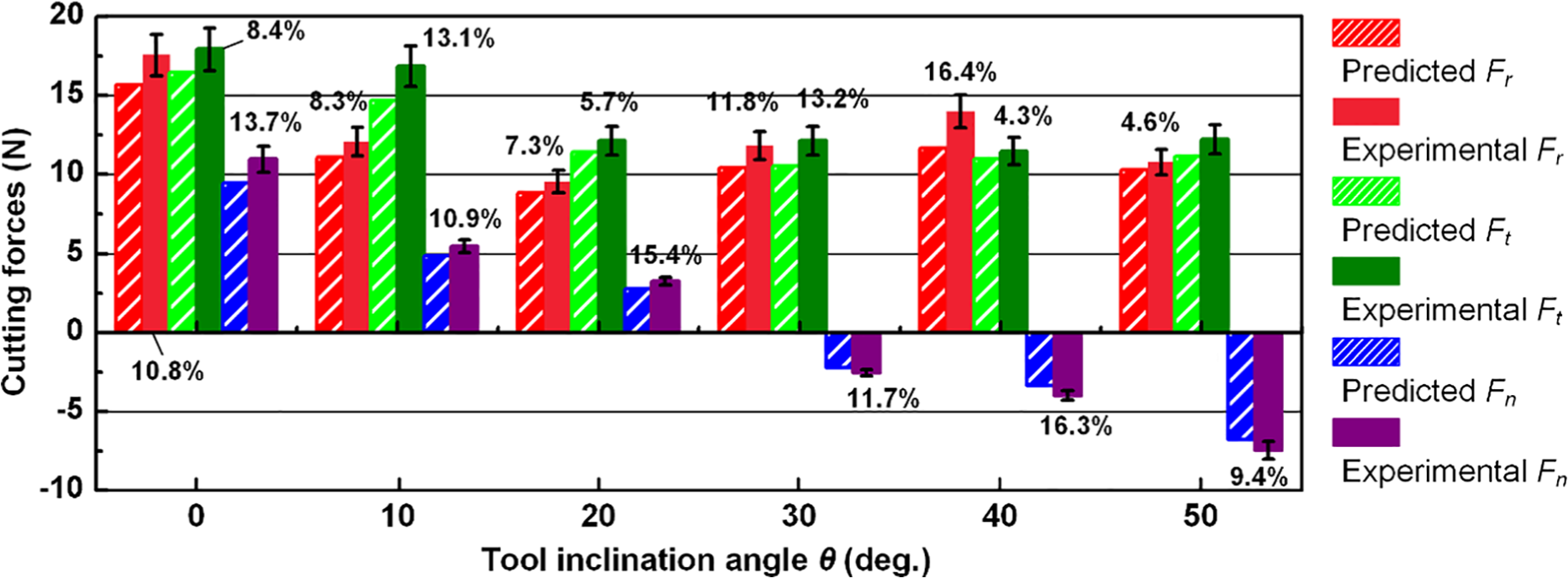
Comparison of the predicted and experimental maximum/minimum forces.
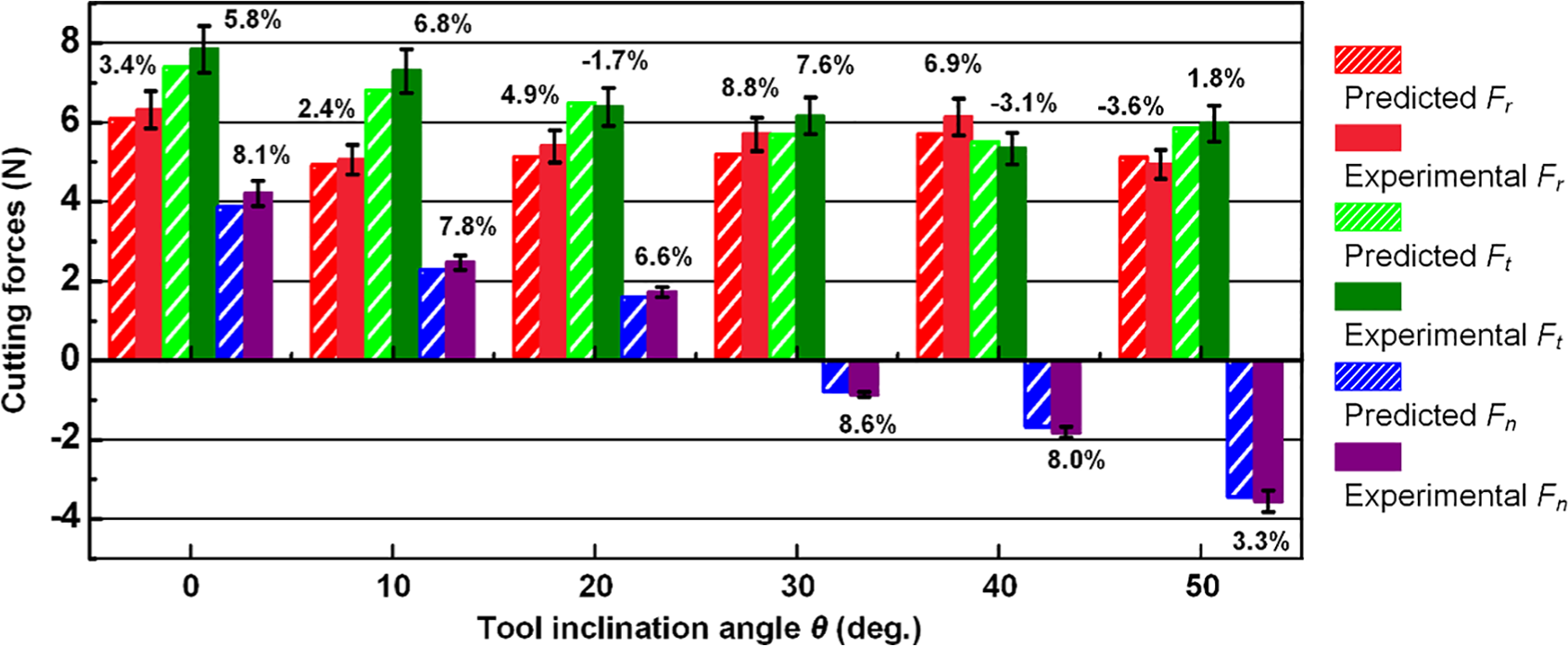
Comparison of the predicted and experimental average forces.
It can be seen that the maximum value of the experimental Fn changes significantly in comparison with the other two force components Ft and Fr when θ changes (see Figure 8), and the average value of the experimental Fn changes with the similar tendency (see Figure 9). With the increase of θ, the value of Fn changes from positive to negative, while the values of Ft and Fr keep positive and decrease only a little. The maximum/minimum force errors between the predicted and the experimental Fr, Ft, and Fn at the investigated tool inclination angles are less than 16.4%, while the average force errors are less than 8.8%. According to these results, the FE model proposed in this article is well validated.
It is noted that the average cutting forces errors between the predicted and the experimental results are generally smaller than the maximum/minimum forces errors. This is because the random trial errors, for example, the machine tool vibration and the clamping errors, are unavoidable when conducting the experiments, and the maximum cutting forces values would be greatly affected by them. However, the random errors could be eliminated to some extent for the average cutting forces due to the accumulation processes. In the following sections, the average values of the cutting forces would be used for further discussing their variations.
Cutting forces adaption based on tool inclination angle
Variation of cutting forces
According to the variation curves of average Fr, Ft, and Fn obtained from the simulations (see Figure 10), the values of Fr and Ft are close and they show very small changes near 6 N with the increase of θ. Oppositely, Fn shows a quite different variation from the other two components that changes from the positive value 3.87 N to the negative −3.44 N (i.e. the direction of Fn changes to the opposite) when θ increases from 0° to 50°. As for the absolute value of Fn, it varies in a concave line with the minimum value of 0.26 N.
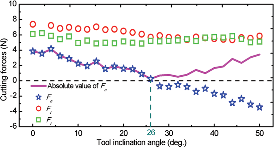
Variation of the predicted Fr, Ft, and Fn with θ.
As Fn is imposed in the perpendicular direction of the thin workpiece edge, where the stiffness is far much lower than that in the other two directions. The significant change of the Fn value and even its direction would undoubtedly influence the side milling stability of the thin-walled workpiece to a large extent, which would inevitably cause defects to the machined surface finish. In comparison with Fn, the changes of Fr and Ft are much smaller, and more importantly, the workpiece stiffness in the two forces directions is much higher. Thus, it can be easily concluded that the influences of Fr and Ft on the workpiece stability during the variation of θ should be much smaller and therefore, they can be reasonably neglected in the investigation of side milling thin-walled workpiece edges. Besides, more attention should be paid on the variation regularity of Fn with θ. According to these assumptions and related experimental facts, the optimal tool inclination angle for finally improving machined surface finish should be 26° when the absolute value of Fn reaches the minimum.
Chip formation—the force adaption mechanism
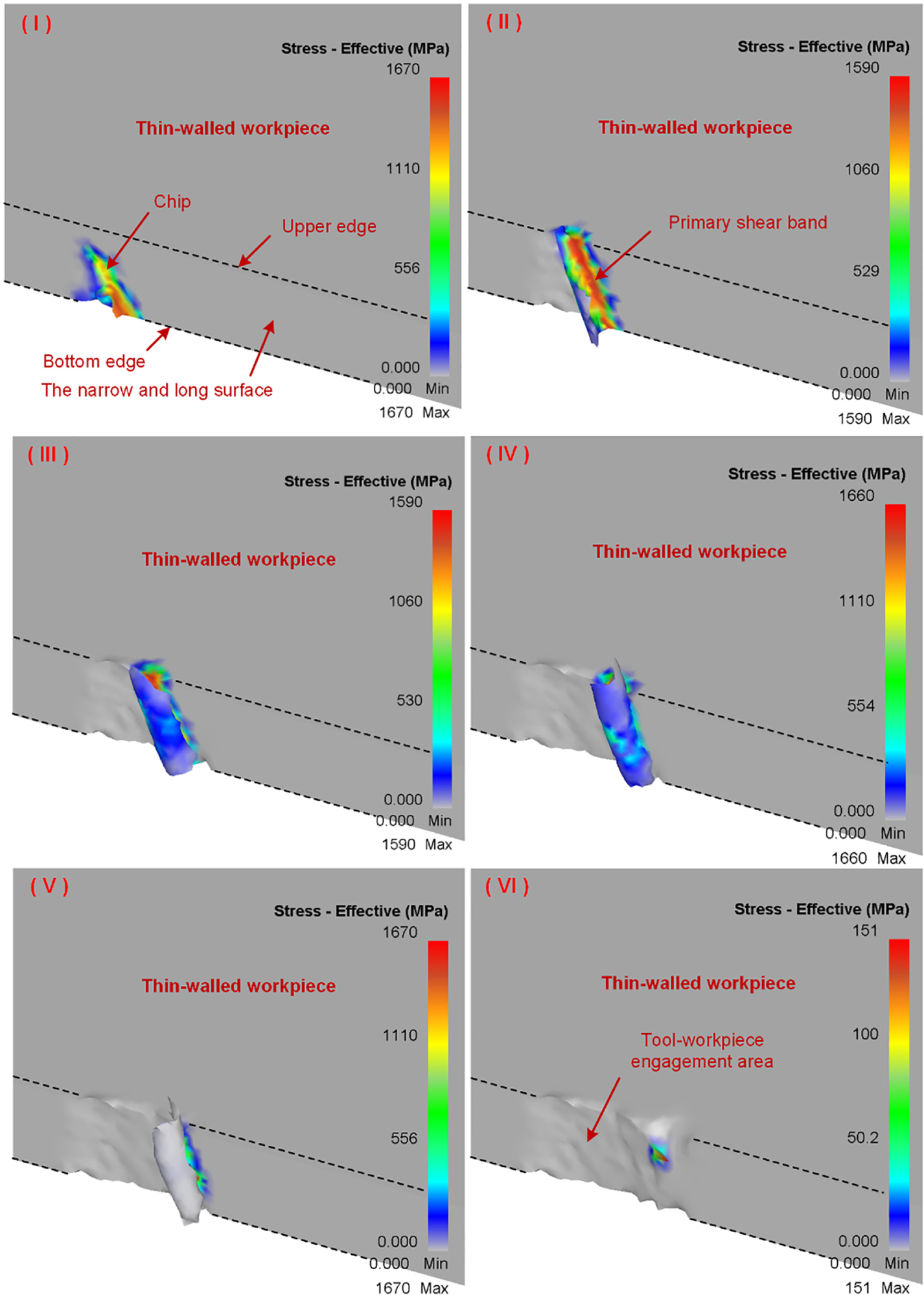
The cutting forces variations are highly related with the chip formation procedures. 20 The adaptions of the cutting forces under different tool inclination angles when side milling the thin-walled workpieces are further investigated based on the chip formations by using the FE simulations. Here, the time-varying procedures of the chip formation under the condition of θ = 20° are given for ease of explanation (see Figure 11). When the tool cutting edge moves from the beginning to the end of the tool–workpiece engagement area, the chip morphologies at different tool rotation stages (marked as I–VI sequentially) vary a lot. The whole procedures can be divided into two periods. For the first period, the chip forms at the bottom edge of the narrow machining surface (Stage I) and grows into a full chip when the primary shear band reaches the upper edge (Stage II), then, the chip grows and curls successively and the chip thickness increases until reaching the maximum (Stage III). The second period just follows the first one, during which the chip curls successively but the chip thickness decreases (Stage IV). Then, the primary shear band of the chip begins to leave the bottom edge of the narrow machining surface and its length becomes shorter (Stage V). Finally, the chip is separated from the workpiece (Stage VI). The two periods of chip formation procedures could well illustrate the increase and the subsequent decrease of the time-varying forces in Figures 6 and 7.
Chip formation procedure during the engagement of one tool cutting edge with the workpiece at θ = 20°.
The chip morphologies under different tool inclination angles are also acquired at the time when the chip thicknesses reach the maximum (see Figure 12). To compare them quantitatively, the chip formation angle, chip curling height, and chip curling width are defined and measured (marked in each figure), and their variations with the tool inclination angle are drawn (see Figure 13). As the tool inclination angle increases, both the chip curling height and width change slightly near 0.55 and 0.74 mm, respectively, while the chip formation angle changes almost linearly from the positive value 28.2° to the negative value −17.5°. Evidently, the chip formation angle has a similar variation trend and therefore could intuitively illustrate that of Fn. As the chip shearing force is much larger than the tool–workpiece friction force in the cutting area, the resultant force of them acts nearly perpendicular to the primary shear band of the chip. When the chip formation angle changes under the influence of the tool inclination angle, the normal cutting force component of the resultant force, that is, Fn, would also change. In sum, the variations of both the amplitude and direction of Fn are determined by the variations of the chip thickness and chip formation angle. It is noted that the optimal tool inclination angle obtained in the “Variation of cutting forces” section is near but not equal to the angle (approximately 29°, see Figure 13) at which the chip formation angle reaches zero. The error could be caused by influence of the tool–workpiece friction force generated during the cutting process.
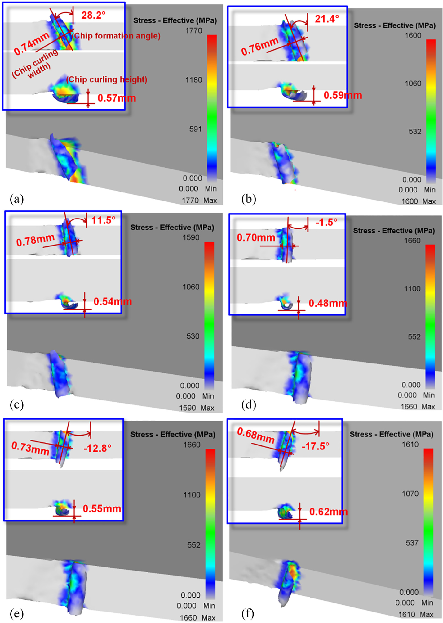
The chip formation morphologies at different tool inclination angles: (a) θ = 0°, (b) θ = 10°, (c) θ = 20°, (d) θ = 30°, (e) θ = 40°, and (f) θ = 50°.
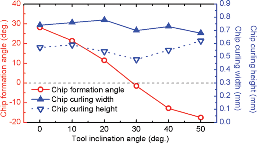
Effects of tool inclination angle on the chip formation angle, chip curling width, and curling height.
Effects of the tool inclination angle on machined surface finish—Validation of the prediction
As introduced in the “Experimental details” section, the machined surface testing trials using low-stiffness thin-walled workpieces were conducted in order to investigate the effects of the tool inclination angle on the machined surface finish and validate its improvement performances based on the aforementioned prediction.
Vibration amplitudes
The vibration amplitudes of the thin-walled workpiece were collected at the middle of the workpiece edges and at the time when the tool moved across the middle position. Under the investigated conditions, it is clear that the workpiece vibration amplitude first decreases and then increases with the increase of the tool inclination angle, and it reaches the minimum 7.64 μm at the predicted optimal angle 26° (see Figure 14). The result could well validate the effectiveness of the proposed tool inclination method on the workpiece vibration suppression performance when side milling the low-stiffness thin-walled workpiece edges.
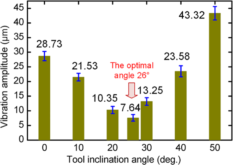
Variation of the workpiece vibration amplitudes with the tool inclination angle.
Surface roughness
The variations of the surface roughness Ra, Rq, and Rz measured in the machined surface finish testing trials with respect to the tool inclination angle are similar to that of the vibration amplitude (see Figure 15). All of them reach the minimum value 0.44, 0.58, and 2.94 μm, respectively, at the predicted optimal angle 26°. The results indicate that the machined surface finish is strongly influenced by the machining vibration of the workpiece and could be improved by using the proposed tool inclination method based on the FE model.
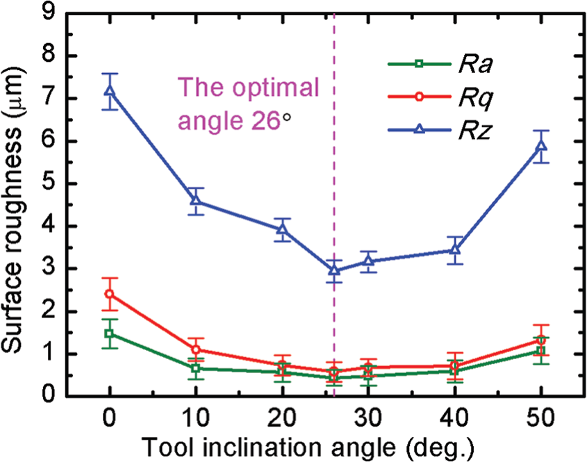
Variation of machined surface roughness Ra, Rq, and Rz with θ.
Surface morphologies
The machined surface topographies at the middle of thin-walled workpiece edges under the investigated tool inclination angles are acquired through the optical microscope (see Figure 16). The evenly distributed and mutually parallel stripes can be clearly seen on these surfaces. In each graph, the angle between the stripes and the perpendicular direction of the tool feed is equal to the tool inclination angle, which indicates that these stripes are caused by the periodical cutting of the milling tool. In comparison, the texture under the predicted optimal tool inclination angle 26° appears to be more regular with less vibration-induced blurred regions than that under the other inclination angles. It implies that the slighter vibration and better surface finish could be obtained at the suggested optimal tool inclination angle.
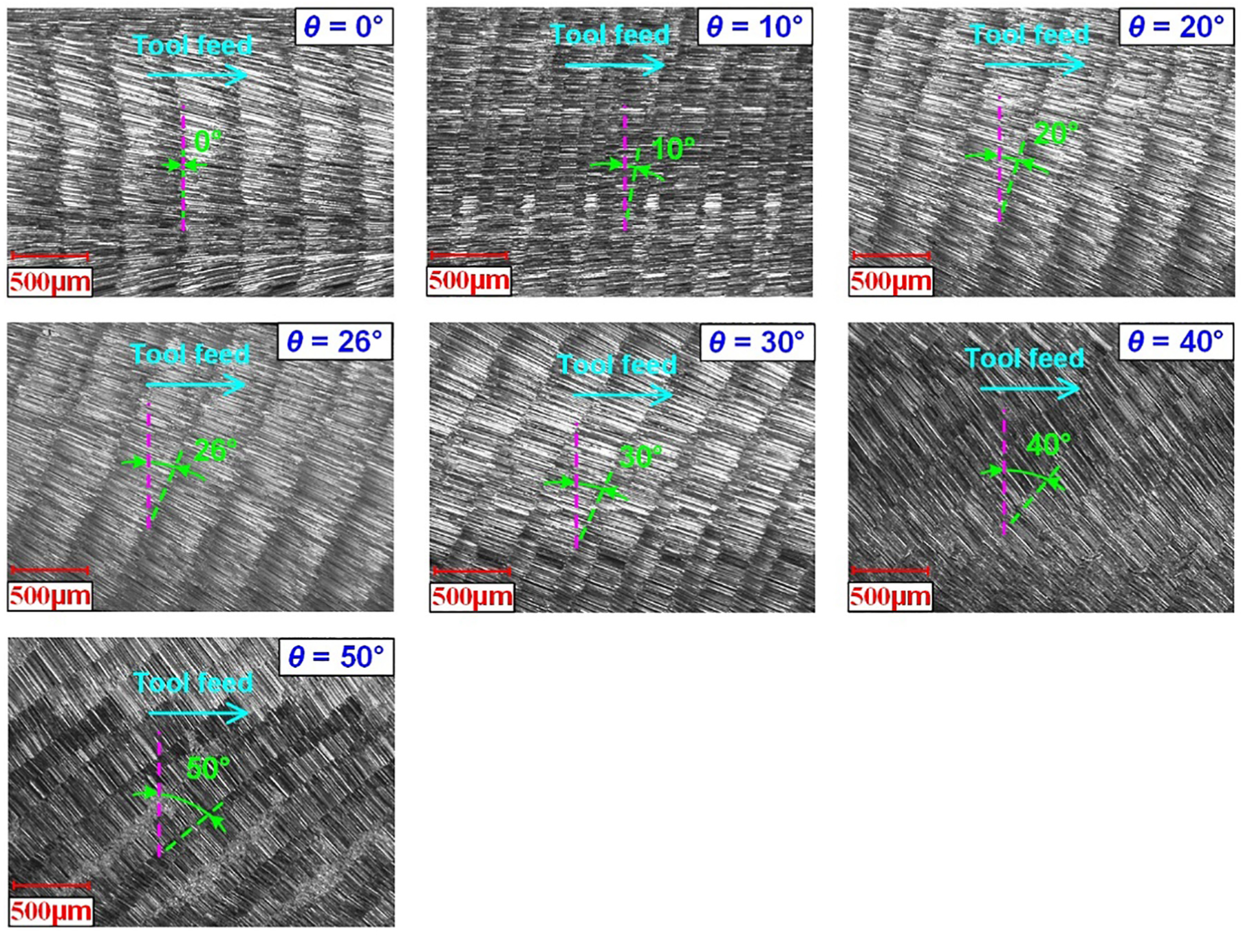
Topographies of the machined surfaces at different tool inclination angles.
Based on the above experimental results of the vibration amplitudes, surface roughness, and surface morphologies, the proposed tool inclination method with the solid end mill based on the FE model to improve the machined surface finish in side milling of the thin-walled workpiece edges is well validated. This method is meaningful and feasible for the high-quality and high-efficiency manufacturing processes of thin-walled workpieces.
Conclusions
Due to the significance and highly required machined surface finish of the process of side milling thin-walled workpiece edges, the tool inclination method with the solid end mill based on the FE model was proposed. The FE models were elaborated for investigating the effects of tool inclination angles on the variations and further the variation mechanisms of cutting forces as the main causes of machining vibrations, based on which the optimal inclination angle for the high-quality and high-efficiency side milling process was suggested. In terms of cutting forces, the proposed FE models were well validated by the cutting forces testing trials. After that, the vibration suppression and machined surface finish improvement performances at the predicted optimal tool inclination angle were also validated by the machined surface finish testing trials. The proposed tool inclination method based on the FE model to improve the machined surface finish is meaningful and feasible for the practical manufacturing processes of thin-walled workpieces.
Footnotes
Appendix 1
Declaration of conflicting interests
The author(s) declared no potential conflicts of interest with respect to the research, authorship, and/or publication of this article.
Funding
The author(s) disclosed receipt of the following financial support for the research, authorship, and/or publication of this article: Financial support for the research is acknowledged. This work was supported by the National Natural Science Foundation of China (No. 51705319), the Shanghai Pujiang Program (No. 17PJ1403800), the Shanghai Academy of Spaceflight Technology (SAST-060), and the State Key Laboratory of Mechanical System and Vibration (No. MSVZD201704).