
Abstract
The Ni-Co/SiC composite coatings were prepared via jet electrodeposition in the presence of magnetic field. The microstructure and texture orientation of the composite coatings were analyzed via field emission scanning electron microscopy, three-dimensional profiling, and X-ray diffraction. The microhardness and wear resistance were characterized by a microhardness tester and a friction–abrasion testing machine. The results indicated that nano-SiC particles improved the surface morphology of the Ni-Co/SiC composite coating. In jet electrodeposition, globular structure aggregation began to form protrusions in the Ni-Co/SiC composite coating due to nanoparticle agglomeration when 6 g/L of nano-SiC was added. The Ni-Co/SiC (6 g/L) composite coating became uniform and densification by jet electrodeposition in magnetic field, with higher microhardness and better wear resistance. The microhardness of the Ni-Co/SiC composite coating increased to 626 ± 14 HV, and the corresponding friction coefficient was as low as 0.317.
Introduction
Ni-Co alloy coatings were widely used in engineering material production, due to their high hardness, wear resistance, and high temperature resistance.1–3 Nanoparticles have been widely used in the alloy coating to improve the properties of composite coatings. However, nanoparticles tended to agglomerate due to their high surface energy, resulting in an uneven distribution in the composite coating, which is disadvantageous for the composite coatings.4–6 Therefore, the uniform distribution of nanoparticles in composite coatings remains an important issue that needs to be solved.
The electrochemical deposition technique was commonly used to deposit the composite coatings.1–10 Many researchers improved the dispersibility of nanoparticles in composite coatings by additives, 1 pulse plating,2,3 co-deposition,4,5 stirring,6,7 and ultrasonic-assisted pulse plating.8,9 These were limited to immersion tank deposition, the electrolyte had poor fluidity, and the equipment process was complex.6–10
Different from the above research, in this article, we used high-speed jet electrodeposition.11–13 Normally, it is easy to agglomerate and settle in the liquid storage tank when the content of nanoparticles is larger in jet electrodeposition. Therefore, it is necessary to improve the dispersion of nanoparticles using an external composite technology.11,14 Magnetic field, as a kind of physical field, is being used widely in composite machining in recent years.15–17 In this work, Ni-Co/SiC composite coatings were co-deposited by jet electrodeposition in the presence of magnetic field. The growth of metal ion discharge was regulated by magnetic field to promote the uniform distribution of nanoparticles in composite coating. The existence of magnetic field not only affected the microstructure and wear resistance of alloy, but also improved the uniform distribution of nanoparticles in the coating.
Experimental
Experimental installation
Figure 1(a) shows a schematic diagram of jet electrodeposition in the presence of magnetic field. The physical objects of the equipment are shown in Figure 1(b) and (c). The jet electrodeposition system mainly includes a power supply, a nozzle system, a transmission system, a control system, and a water bath system. The sample was clamped on the surface of the cathode and reciprocated under the control of the motor during processing. The electrolyte was sprayed on the surface of the cathode by a nozzle, and the electrochemical deposition occurred under power supply.
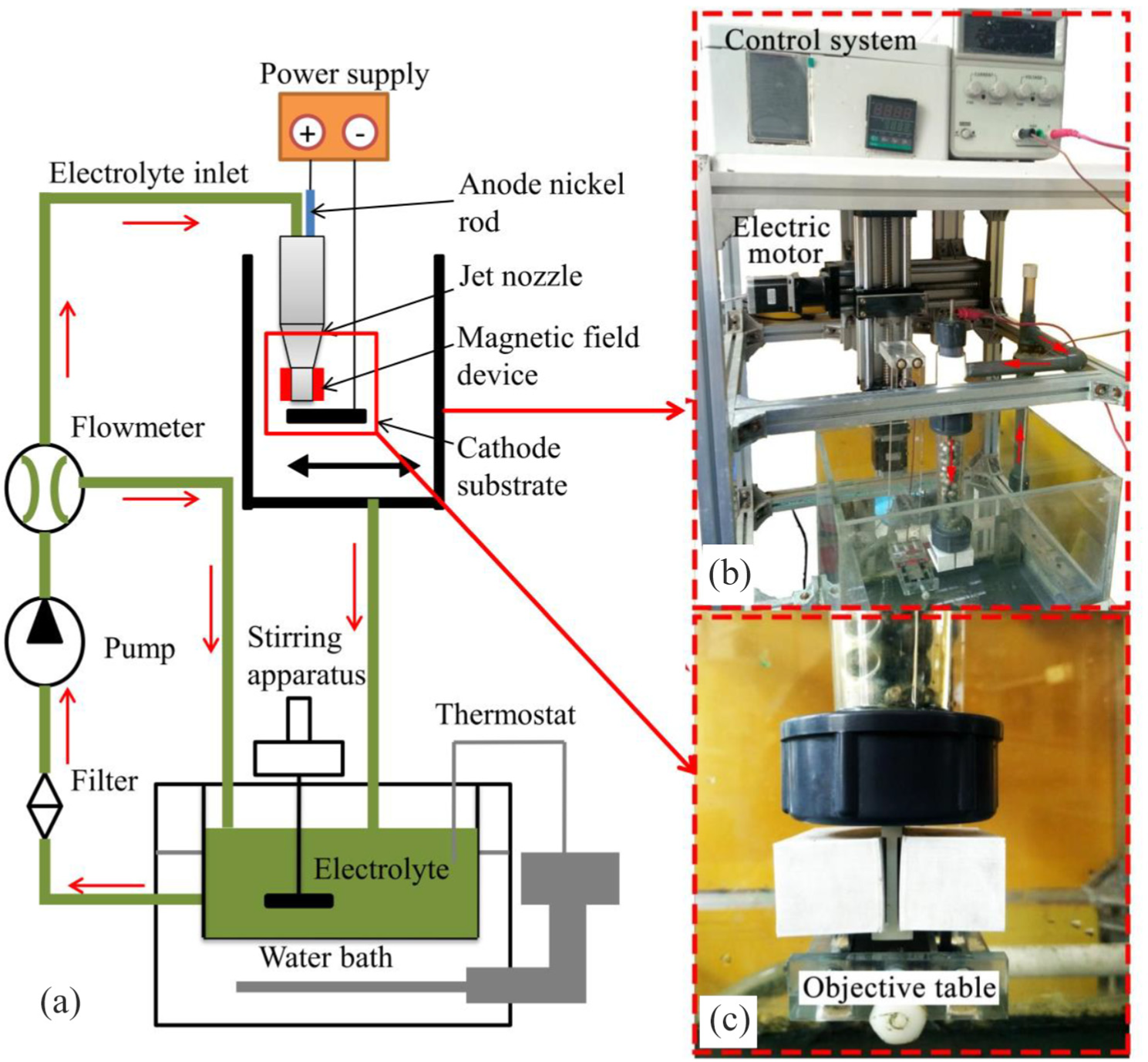
(a) Schematic diagram of jet electro deposition in the presence of magnetic field, (b) Physical objects, and (c) Nozzle structure.
Different from the traditional immersion electrodeposition of channel plating, jet electrodeposition was performed using a high-speed flowing electrolyte to impinge on the surface of the cathode. Under the action of the external electric field, the ions in the electrolyte were adsorbed and deposited on the surface of the cathode to form a coating. The bubbles and impurities generated by the side reaction of the electrodeposition were also removed in time with the high-speed flowing electrolyte. The magnetic field was suspended from the nozzle outlet. The magnetic field was provided by a magnet suspended at the exit of the nozzle.
Material and surface treatments
The electrolyte composition and processing parameters are shown in Table 1. All experimental reagents were of analytical grade. The electrolyte flow rate in this experiment was 4 m/s and the processing time was 30 min. In electrolyte composition, NiSO4·6H2O and NiCl2·6H2O provided Ni2+ and CoSO4·7H2O provided Co2+. In addition, NiCl2·6H2O acted as an anode activator, Cl− was adsorbed on the anode to prevent passivation of the coating. H3BO4 was used to adjust the pH value and also enhance the electrolyte polarization layer. Usually, the pH of the electrolyte was as low as 3.0–3.5 due to the addition of an appropriate amount of H3BO4 when the plating solution was configured. In order to ensure that the pH was in the range of 4.0 ± 0.1, we gradually added a small amount of NH3·H2O to adjust the electrolyte. C7H5O3NS is called saccharin, which acted as a brightener to improve the brightness of the coating.
Electrolyte composition and processing parameters.
The nano-SiC (40 nm) was ultrasonically shaken for 60 min and magnetically stirred for 2 h. The sintered NdFeB samples were used as the cathode substrate and a nickel rod (99.99%) acted as the anode. Prior to the experiment, the samples were polished, sealed, degreased, and cleaned. The jet electrodeposition system with the magnetic field device was used to maintain the magnetic field strength at 0.5 T, and the magnetic field was perpendicular to the flow direction of the electrolyte.
Methods of characterization
The surface morphology and elemental analysis of the coatings were characterized by field emission scanning electron microscopy (FSEM-S4800) and energy-dispersive X-ray spectroscopy (EDS). The surface roughness and three-dimensional (3D) shape of the coatings were observed by a 3D optical profiler (S-neox 3D Profiler). The resolution of the optical profiling was 1360 × 1024. The margin of error was ±0.5% (in the thickness of the coating (Z-axis)). The acquisition area was 876.55 × 659.83 μm2, and the surface roughness was the average value automatically. The coatings were analyzed by an X-ray diffraction (XRD) spectrometer (D/MAX-2500PC) operated at 40 kV and 150 mA, with Cu-Kα radiation (λ = 1.5406 Å) to determine the phase composition and crystallite size. The microhardness of the coatings was measured with a microhardness tester (HVS-1000D) at a load of 200 g. The microhardness was measured at five points for each sample, and the average value was taken as the hardness of the composite coating. The friction and wear were performed by a friction–abrasion testing machine (HSR-2M), loaded for 10 min, ran at 300 r/min, and loaded at 15 N.
Results and discussion
Surface morphology
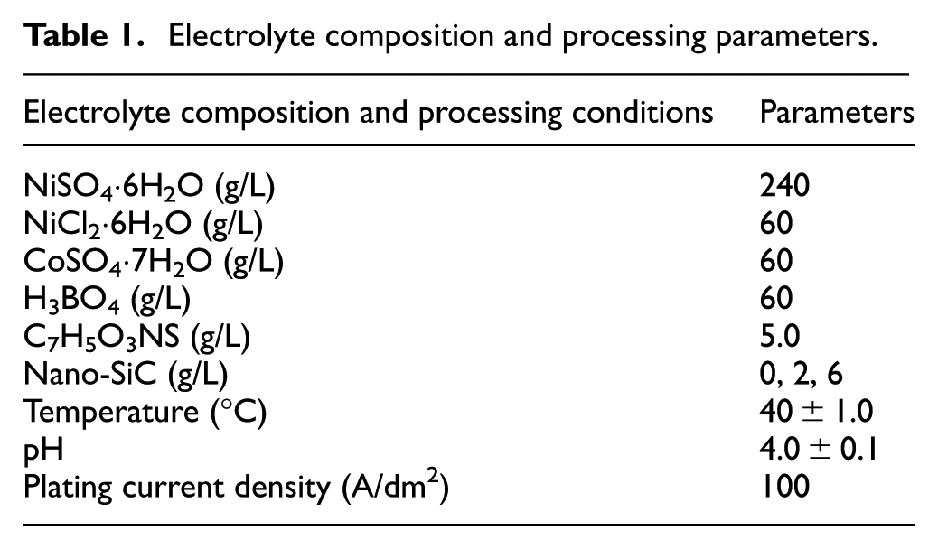
Figure 2 shows the SEM morphology of the Ni-Co alloy and the Ni-Co/SiC composite coatings. There are many large cellular protrusions in the Ni-Co alloy coating shown in Figure 2(a). Figure 2(b) illustrates the Ni-Co/SiC (2 g/L) composite coating having many smaller globular structures, rather than the previous large cellular protrusions. The black spots in the surface morphology were analyzed by EDS, the corresponding peak values of Si elements in C and Si elements were detected, and the existence of nano-SiC in the composite coating was proved. Figure 2(c) shows many small globular structures aggregating and growing large cellular structures in the Ni-Co/SiC (6 g/L) composite coating when the content of nano-SiC was further increased to 6 g/L. However, from Figure 2(d), no micro-protrusions were observed and the crystal nucleus with nano-SiC particles as the growth point was more evenly distributed in the composite coating in the presence of magnetic field.
SEM morphology and EDS of the coatings: (a) Ni-Co, (b) Ni-Co/SiC (2 g/L), (c) Ni-Co/SiC (6 g/L)—no magnetic field, and (d) Ni-Co/SiC (6 g/L)—with magnetic field.
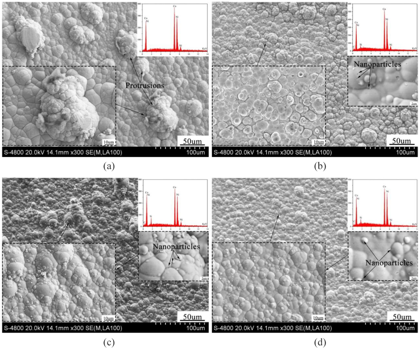
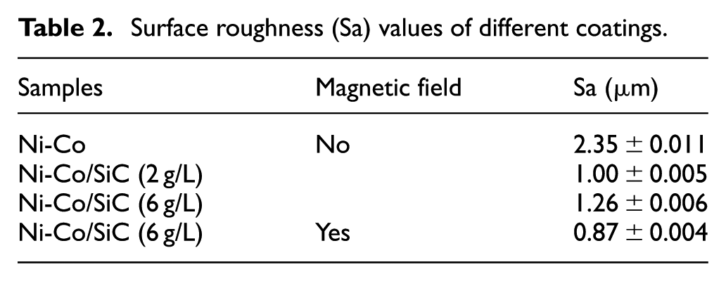
Figure 3 shows the 3D profile images of the coatings. Table 2 indicates the surface roughness of the different coatings; the surface roughness of the Ni-Co alloy coating was up to 2.35 ± 0.011 μm, and the surface roughness of the Ni-Co/SiC (2 g/L) composite coating was obviously reduced to 1.00 ± 0.005 μm.18,19 It was directly related to the growth of microprotrusions on the SEM morphology analyzed above. However, the surface roughness of the Ni-Co/SiC (6 g/L) composite coating increased to 1.26 ± 0.006 μm as shown in Figure 3(c), which was related to a large amount of nano-SiC agglomeration and reduced the growth quality of the composite coating. In Figure 3(d), the surface roughness of the Ni-Co/SiC (6 g/L) composite coating improved effectively by jet electrodeposition in the presence of magnetic field, as low as 0.87 ± 0.004 μm. 20
3D profile images of the coatings: (a) Ni-Co, (b) Ni-Co/SiC (2 g/L), (c) Ni-Co/SiC (6 g/L)—no magnetic field, and (d) Ni-Co/SiC (6 g/L)—with magnetic field.
Surface roughness (Sa) values of different coatings.
The thickness of the coatings is shown in Figure 4. It can be seen that the thickness of the coatings decreases in the presence of magnetic field. In the presence of magnetic field, the viscosity coefficient of the electrolyte is lowered, and the wettability between the particles and the plating solution and the conductivity of the electrolyte are improved. On the contrary, the magnetohydrodynamics generated by the magnetic field accelerates the convection of the electrolyte, it promotes mass transfer near the electrode, enhances the transmission of charged particles, reduces concentration polarization on the cathode surface, builds waves in the diffusion layer, makes the electrodeposition take place at a higher overpotential, accelerates the formation rate of the crystal nucleus, but decreases the growth rate. As a result, the nucleus is small and the surface grain is refined. 19
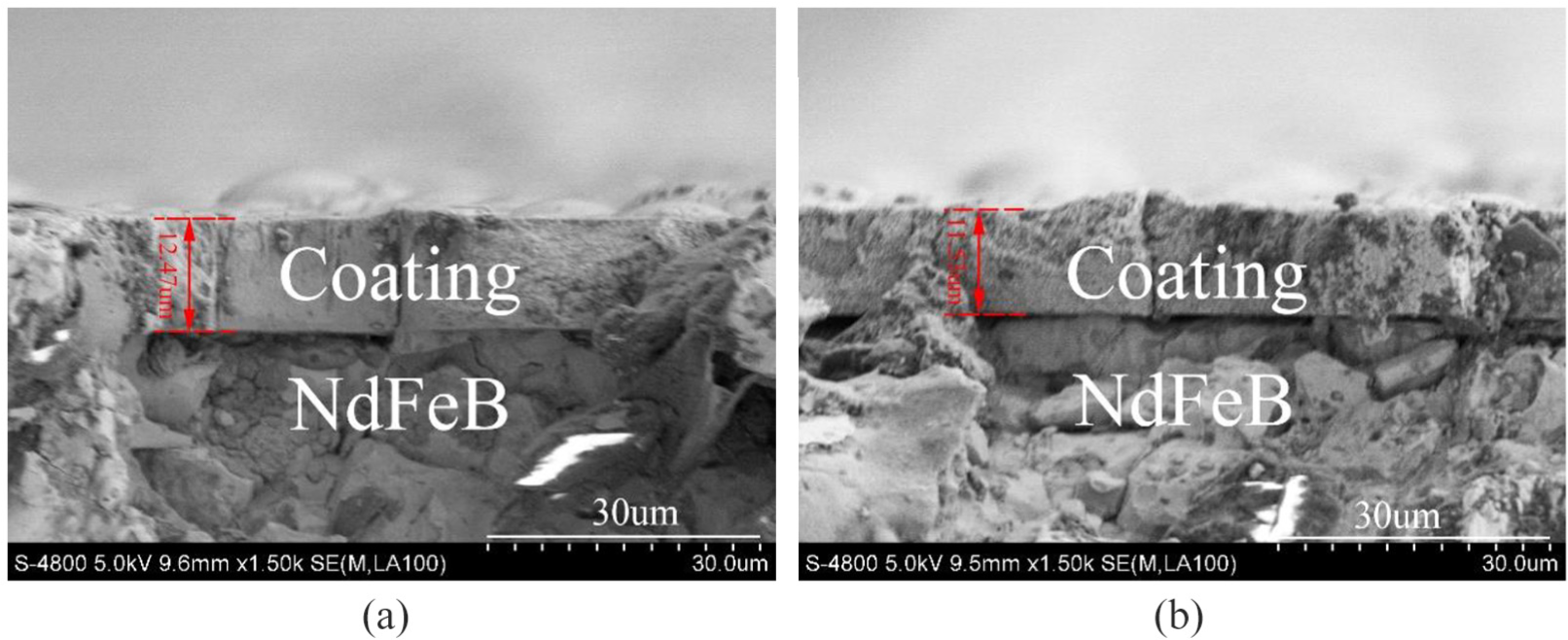
Thickness of the coatings: (a) Ni-Co/SiC (6 g/L)—no magnetic field and (b) Ni-Co/SiC (6 g/L)—with magnetic field.
Texture orientation
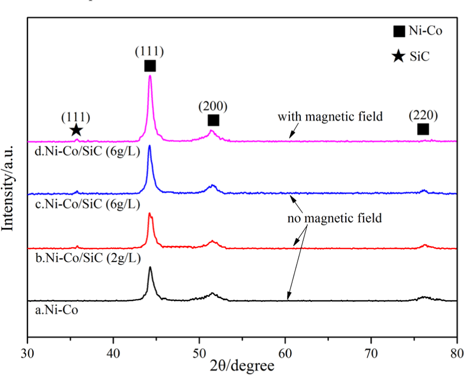
Figure 5 illustrates the XRD patterns of the composite coatings with various nano-SiC concentrations. The coatings had a face-centered cubic (FCC) crystal structure (PDF no. 04-0850). The texture coefficient (TChkl) was used to represent the preferred orientation change of the crystal face

where I(hkl) is the diffraction intensity of the crystal face of the Ni coating (s−1) and I0(hkl) is the diffraction intensity of the standard Ni crystal face (s−1).
XRD patterns of the composite coatings: (a) Ni-Co, (b) Ni-Co/SiC (2 g/L), (c) Ni-Co/SiC (6 g/L)—no magnetic field, and (d) Ni-Co/SiC (6 g/L)—with magnetic field.
The peak of the Co phase was not found, since the radii of Ni and Co atoms were similar, Co entered the lattice of Ni atoms in the form of atoms, thereby further generating a single-phase Ni-Co solid solution, which was similar to the previous reports.21–23 According to Scherrer, the relative strength and crystal face diameter of different peaks of Ni in the composite coatings are shown in Table 3. 11 The addition of nanometer SiC weakened the (220) crystal plane and strengthened the (111) crystal plane. In jet electrodeposition with magnetic field, the diffraction peak of the crystal plane broadened, the grain size was further refined, and the surface of the composite coating became more compact.
Relative strength and crystal face diameter of different peaks of Ni in the coatings.
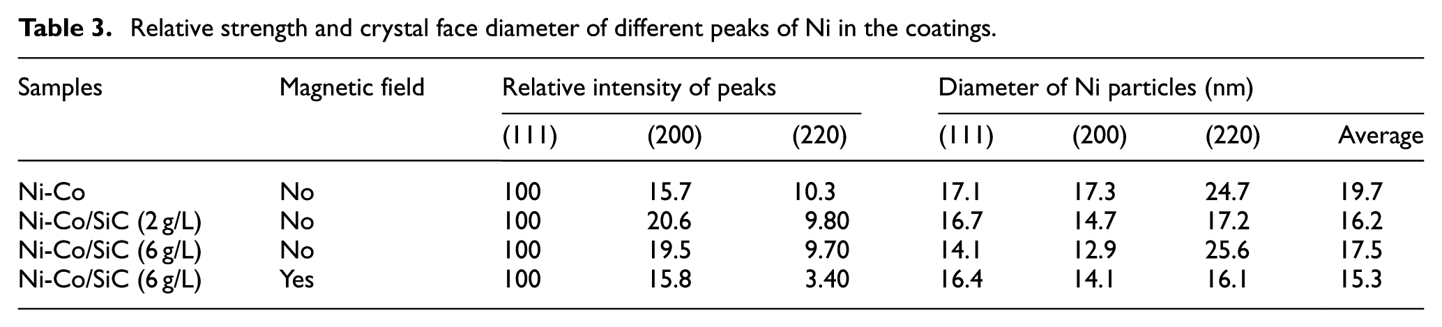
With the addition of nano-SiC (2 g/L), the average diameter of the crystal face was refined from 19.7 to 16.2 nm of the Ni-Co alloy coating. Nano-SiC had a refinement effect on the grains of the Ni-Co/SiC composite coating. When the amount of nano-SiC was 6 g/L, the agglomeration of nanoparticles affected the average grain size of the composite coating, which led to the increase of the average diameter of the crystal face to 17.5 nm. Nonetheless, in the jet electrodeposition with magnetic field, the grain size of the Ni-Co/SiC composite coating was refined to 15.3 nm.
Microhardness and wear resistance
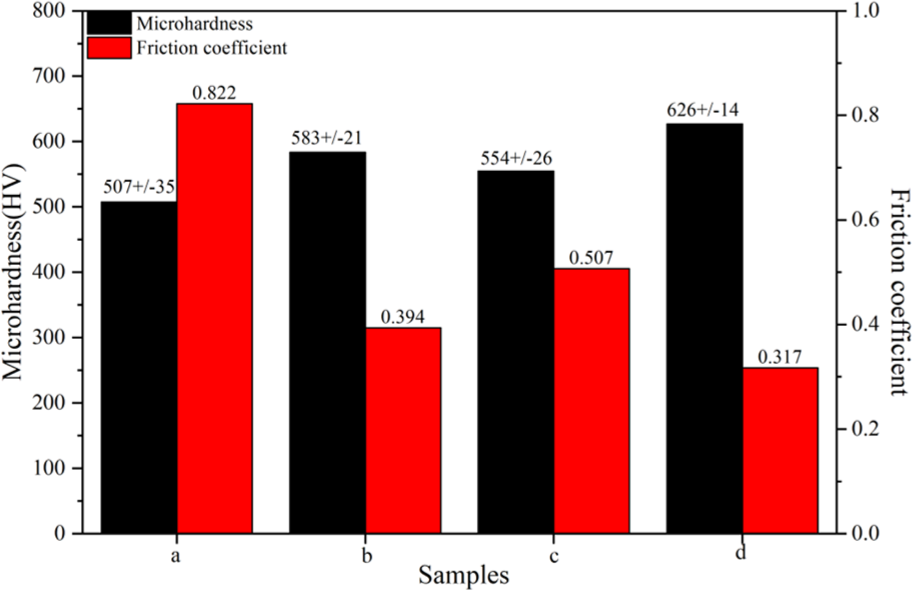
Figure 6 shows the microhardness and friction coefficient of the composite coating. The microhardness of the Ni-Co/SiC composite coatings was higher than that of the Ni-Co alloy coating. The friction coefficient had also changed significantly, which was related to the smoothness of the coating surface morphology. Figure 7 illustrates the SEM images of the worn surfaces of the coatings after the wear test. The Ni-Co alloy coating had obvious peeling and separation belonging to fatigue wear and oxidation wear in Figure 7(a). 10 Figure 7(b) shows that the Ni-Co/SiC (2 g/L) composite coating had some debris, delamination, and furrow grooves parallel to the direction of the frictional motion. The wear mechanism was dominated by abrasive wear. There were some microcracks and delamination in the Ni-Co/SiC (6 g/L) composite coating as shown in Figure 7(c). The Al element was detected by the EDS analysis of the wear debris attached to the coating. The Al2O3 ceramic ball was used as a friction pair. The friction mechanism had abrasive wear and adhesive wear. Figure 7(d) shows that the Ni-Co/SiC (6 g/L) composite coating had shallow grooves and no microcracks, which was deposited by jet electrodeposition in the presence of magnetic field. The microhardness and friction coefficient also indicated that the wear resistance was improved as shown in Figure 6. 24
Microhardness and friction coefficient of the coatings: (a) Ni-Co, (b) Ni-Co/SiC (2 g/L), (c) Ni-Co/SiC(6 g/L)—no magnetic field, and (d) Ni-Co/SiC (6 g/L)—with magnetic field.
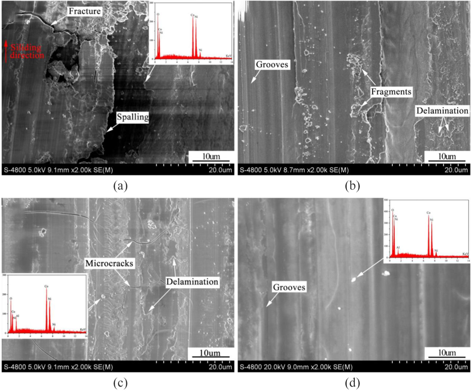
SEM images of the worn surfaces of the coatings: (a) Ni-Co, (b) Ni-Co/SiC (2 g/L), (c) Ni-Co/SiC (6 g/L)—no magnetic field, and (d) Ni-Co/SiC (6 g/L)—with magnetic field.
Nano-SiC was dispersed as a hard spot in the composite coating to refine the grain size. According to the Hall–Petch formula, the finer the grain, the higher the strength of the material. 25 Nano-SiC embedded in the coating reduced the direct contact between the coating and the grinding ball during the sliding process and improved the wear resistance. However, when the content of nano-SiC was too high in the electrolyte, it was easy to agglomerate, resulting in poor quality of the coating, such as protrusions and microcracks. The friction and wear began from the protrusions. 26 The agglomerated nano-SiC acted as an abrasive grain, which exacerbated wear. Magnetic field was beneficial for improving the uniform distribution of nano-SiC, coating surface morphology, and smoothness. In addition, the uniform distribution of nano-SiC in the coating played a self-lubricating role in the friction and wear process, so the wear resistance was improved.
Conclusion
The results showed that the agglomeration of nanoparticles could be effectively improved by jet electrodeposition in the presence of magnetic field. The cations were deflected in the presence of magnetic field, which increases the contact probability of cations to the nano-SiC in electrolyte and improves the uniform flatness, microhardness, and wear resistance of the composite coatings. This showed that jet electrodeposition in the presence of magnetic field was an effective method for improving the uniformity of the composite coatings.
The roughness decreased from 2.35 ± 0.011 μm of the Ni-Co alloy coating to 0.87 ± 0.004 μm of the Ni-Co/SiC composite coating in the presence of magnetic field.
The peak of the Co phase was not found in the Ni-Co/SiC composite coating since the radii of Ni and Co atoms are similar and Co enters the lattice of Ni atoms in the form of atoms, thereby further generating a single-phase Ni-Co solid solution.
The microhardness of the composite coating increased from 507 ± 35 HV of Ni-Co alloy coating to 626 ± 14 HV of Ni-Co/SiC composite coating, and the corresponding friction coefficient decreased from 0.822 to 0.317, which improved the mechanical properties of the composite coating.
Footnotes
Declaration of conflicting interests
The author(s) declared no potential conflicts of interest with respect to the research, authorship, and/or publication of this article.
Funding
The author(s) disclosed receipt of the following financial support for the research, authorship, and/or publication of this article: This work was supported by the scholarship from China Scholarship Council (CSC) under the Grant CSC No. 201906830024, the Nanjing University of Aeronautics and Astronautics PhD Short-Term Visiting Scholar Project (Grant No. 190102DF05), the National Natural Science Foundation of China (Grant Nos. 51475235, U1537105, and 51105204), and the National Key Laboratory of Science and Technology on Helicopter Transmission (Nanjing University of Aeronautics and Astronautics) (Grant Nos. HTL-A-19G011 and NT2018016). We are grateful to the National Key Laboratory of Science and Technology on Helicopter Transmission of Nanjing University of Aeronautics and Astronautics for its support to the experiment.