
Abstract
Size is a fundamental descriptor of objects—it allows us to quantify “how big” objects are and to compare and classify objects based on this notion. In the world of International Organization for Standardization Geometrical Product Specification and Verification, size is defined much more narrowly: it is restricted to features of size, and the methods of inducing size values from an actual workpiece are strictly controlled. The release of ISO 14405-1:2010 has introduced a rich new set of size specification modifiers, which includes two-point and spherical local sizes, least squares, maximum inscribed and minimum circumscribed associations, as well as calculated diameters (inferred from the circumference, area, or volume of the feature of interest). Further modifiers allow the specification of statistics of local size measurements, such as maximum, minimum, range, average, and others. This article will present “size” as a fundamental engineering notion from several viewpoints and trace its evolution in engineering drawings. It will then discuss the implications of the use of the recently standardized size modifiers in engineering design and investigate the issues that may arise in the application and interpretation of these extensions to size.
Keywords
Introduction
Size alone does not describe the geometric quality of an object. Size, form, location, and orientation are the basic geometric descriptors that together allow us to describe mechanical objects—or workpieces—as well as subsets (features) of these workpieces. From the perspective of engineering design, the quality of a product cannot be defined by a single feature; it is the interaction of features that allows mechanisms to function, and the specifics of this interaction that often determine the ultimate quality of the product. It is in this context, the notion of size as a fundamental geometric descriptor of objects should be considered.
A designer decides on appropriate material, surface, and geometric requirements for each component of a product with the intent that components meeting their individual specifications will function properly when assembled. These geometric requirements are indicated as dimensions and tolerances in a part “drawing” (either a two-dimensional paper rendering or a three-dimensional computer representation) using the symbols defined in national and international standards. Demands for improved quality and yield have become more stringent, and these have, in turn, driven tolerances to become tighter to better ensure product functionality.
However, tighter tolerances require better manufacturing and measurement equipments and practices to be used, which result in more expensive components and products. To meet the constant demands for improvement in product quality without unnecessarily increasing the costs of manufacture, designers have sought more sophisticated means of specifying geometric controls through tolerances. The intent of these controls is to capture the geometric requirements necessary for the component to meet the functional requirements of the assembled product, without placing undue constraints on the geometric aspects of the component to which the part function is insensitive.
Two primary strategies have evolved in the quest for finer control over component geometry. The first is the control of population characteristics, through what is known as statistical tolerancing. This method can be used to take advantage of statistical “averaging” over assemblies of several components, which allows less stringent (and therefore cheaper) tolerances to be placed on the individual components in exchange for a (small) probability of product nonconformance. The second strategy is to specify the geometric requirements for individual components with greater fidelity to the actual function required by the component in the final product. While this method can be applied partially through greater training and sophistication of the designer, some desired specifications are outside of the domain thus far supported by traditional geometric controls. The distinction between these two strategies can be summarized by whether the geometric control is applied “from part to part” or applied “within a part.”
This article will address the new specification methods for controlling feature size for an individual feature (i.e. “within a part”) that are now appearing in standards documents. The increased domain of functional specification that is admitted by these size modifiers will be investigated in the rest of the article. Section “Notion of size tolerance” will introduce the notion of size, and section “Traditional size tolerancing and the Taylor principle” will describe how size has traditionally been controlled in standards. Section “Spines, offsets, and scaling” will review methods of describing size variation, and section “Features of size” discusses the special role that features of size play in modern tolerancing standards, which are covered in section “Standards for size tolerancing.” Sections “Uses and implications” and “Open issues” will investigate potential applications for the new size tolerancing syntax and some open issues presented by this expanded domain of specification.
Notion of size tolerance
Size has a strong intuitive meaning and is used to classify objects both qualitatively and quantitatively. In the qualitative use, size is often used comparatively to state A is larger than B. When used for quantitative description, both a value and unit are stated—A is 5 m long. As we move from the descriptive realm of approximate size to the conformance decision of whether an individual part meets a size specification, we are forced to examine this notion more carefully. In general, nominal features of a design have perfect geometry and can therefore be characterized by a single size parameter (e.g. diameter). Setting limits on this size parameter (say, the diameter can vary between 11.99 and 12.01 mm) results in a tolerance specification for the feature that each manufactured workpiece should meet.
While the nominal feature has perfect form, and hence a single size, actual workpieces have imperfect forms, and a single parameter value will not capture the geometry of the actual feature. This leads to two methods of determining conformance to a size specification. The first method is to induce a single value that is representative of the actual feature’s size and compare this value to the tolerance limits, while the second method compares many different size parameters, each obtained from the actual feature to the tolerance limits.
An example of the first method is to perform a least-squares fit to a sample of points from the feature’s surface and use the size parameter from this fit to evaluate conformance to the tolerance. Another example is to find the smallest perfect form feature that contains the actual part and determine conformance based on the size of this perfect form feature. As can be seen from these examples, the basis for this method of size assessment is determining the size of a substitute geometric element that corresponds to the actual feature in some way.
An example of the second method would be to determine the two-point size (say, using a vernier caliper) of the actual feature at many different locations on the feature. If all of these sizes were to be contained in the prescribed tolerance interval, then conformance to the size tolerance is obtained. When using this method, a single representative “size” value is not produced for the actual feature; rather, conformance to the specification requires that each of the many sizes meets the tolerance criterion.
Traditional size tolerancing and the Taylor principle
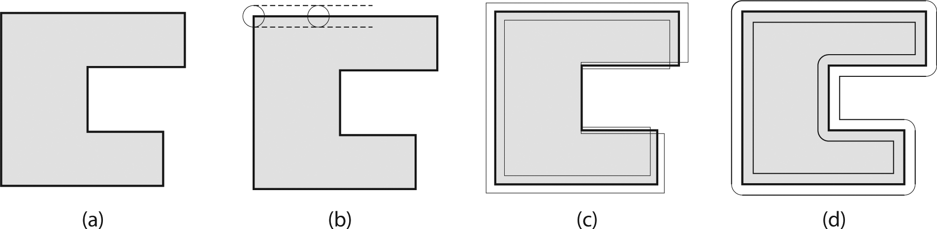
Traditional size tolerances consist of upper and lower limits to the size of a feature, as shown in Figure 1(a) for a solid cylindrical feature. Two size-related functions of the feature are captured using the so-called Taylor principle, a notion of size tolerancing that predates the information age. The first function (assembly, most often) is global in nature, where the entire manufactured feature depicted in Figure 1(b) cannot exceed a theoretical boundary that represents a worst-case mating part as shown in Figure 1(d). The second function (strength, conductance, clearance, or other) is local, where the cross section at any location as indicated by the arrows in Figure 1(c) should not have too little material. While the method of measurement for these features is not specified by the tolerancing standards, it is useful to note the correlation between classical inspection methods and these tolerances. Separate inspection methods are used to determine conformance to the upper and lower size specifications. We will illustrate these methods further using the example shown in Figure 1.
(a) Traditional size tolerancing of a cylindrical pin, (b) actual pin feature that is manufactured, (c) two-point measurement, and (d) global containment.
For this example, the upper size limit captures the size of a theoretical boundary within which the entire cylindrical feature must fit. This has been realized using hard (functional) assembly gauges for many years—if the feature will fit inside a gauge having the size of the tolerance limit, the feature conforms to that tolerance limit. This is a natural example of functional testing—the function is tested by “assembling” the part with the gauge. Figure 1(d) shows the actual feature contained within the bounding envelope. This requirement also enforces a relationship between the size of the feature and the form of the feature. If the part is at its maximum material condition (MMC), then it cannot have any form variation (either out-of-roundness or straightness of its axis), or it will not fit within the boundary. The phrase “perfect form at MMC” is used frequently to describe this relationship.
Continuing our example to the lower size limit, we now wish to evaluate the limit for local size at all locations on the part. This can be envisioned as a two-point measurement using calipers (for our external feature) or other device with opposing measuring faces. There is a subtlety here regarding the two-point measurement, in that different metrology tools will find different pairs of points in the evaluation. Considering the parallel faces of a caliper, the two contact points with the faces may not be diametrically opposed on the feature itself. For the figures in the first two rows of Table 1, it is clear that a pair of vertical lines (representing the caliper faces) will not touch the cross section at points that are diametrically opposite. Certain figures, referred to as curves of constant width (in 2D), will have the same two-point size regardless of the measurement direction, but are not circular in cross section. While such figures may be uncommon in actual definition, they do provide a useful analytical case where the different specification methods will result in a significantly different result. Examples of the Reuleaux triangle, a more rounded extension to the Reuleaux triangle, and a Fourier disk are shown in Table 1. The Reuleaux and Fourier shapes have been shown by Voelcker 1 relating to feature sizes.
Figures of constant width or constant two-point size.
If the two-point measurement is based on diametrically opposed points (i.e. points on a line passing through the center of the cross section), the Reuleaux shapes will not have constant two-point size for measurements in the cross section. However, the Fourier disk (shown in the last row of Table 1) is an example of another noncircular cross-sectional shape with constant two-point size, even when the two-point measurement is required to use diametrically opposed points. The construction of these figures can be extended to any cross sections with an odd number of sides.
While the examples shown here may seem to be contrived, this is no mere geometric curiosity—centerless grinding can produce such artifacts quite easily. It is interesting to observe that 7-sided and 11-sided curves of constant width are deliberately manufactured to mint coins in the United Kingdom and Canada, respectively, as shown in Figure 2. Maintaining the same width all around enables these coins to be used in vending machines just as a circular coin of the same width (or, equivalently, the same diameter). What is more, each of these coins has the same circumference as a circle with the same width; this fact is known as Barbier’s theorem. But each has a smaller area than the corresponding circle—a fact known as the isoperimetric inequality 2 —resulting in material savings when millions of such coins are minted. To clarify, these shapes shown in the following have cross sections of less area than a circular cross section of the same width, resulting in less material used in minting the coins.
Coins of constant width from UK and Canada.
The constraints imposed by the Taylor principle are the basis for the American Society of Mechanical Engineers (ASME) size tolerancing, which defaults to the use of this principle in “Rule #1” of the Y14.5 3 standard. Counter to this, the default principle of the International Organization for Standardization Geometrical Product Specification (ISO GPS) standards is that the size and form of objects are controlled independently, and that both the upper and lower limits of size are controlled by the two-point measurements. Recognizing that different situations call for different requirements, each tolerancing practice has developed syntax that allows the designer to override the default rules—the ASME default is overridden with a statement “Perfect form at MMC not required,” and the ISO default is overridden with a circled E symbol indicating the imposition of an envelope requirement.
As stated at the beginning of this section, the Taylor (or envelope) principle can address two aspects of part functionality: assembly and “minimum material presence.” While this connection is valid, these practices were guided by what can be verified using vernier caliper, micrometer, dial indicators, and hard gauges. The question for the present is what can now be done with the benefit of CMMs and other coordinate measuring systems that collect many points from the surface of the feature? Is it appropriate to simply emulate two-point measurement with these advanced systems, or should we look to expanding the notion of size tolerancing to better capture part function?
One strategy to make size tolerances more function-relevant is to take individual cases where the traditional size tolerances are not adequate for the designer’s intended function and explore how the true functional requirements could be expressed geometrically. This would allow the slow introduction of tolerancing syntax for various component functionalities. Another strategy is to develop a general syntax that describes a broad set of criteria for size and allow the designer to choose among these tools to specify appropriate geometry. This second strategy is implemented in the development and release of the new ISO standard on linear sizes, ISO 14405-1:2011, 4 and is discussed further in section “ISO extensions to size.”
Spines, offsets, and scaling
Voelcker5,6 outlined five conceptions of size. Three of these—parametric size, incremental size, and relative size—can be used interchangeably in describing the classic features of size specified in the tolerancing standards. This relationship is described in more detail in section “Features of size.” A fourth concept, generative size, appears in the ASME Y14.5.1M-1994 Standard, 7 which provides mathematical definitions for geometric tolerances. These mathematical definitions are intended to be consistent with the Y14.5-1994 Standard. Y14.5.1 addresses size in a generative sense, whereby spheres having diameters consistent with the tolerance limits are swept along spines, resulting in the boundaries of a tolerance zone to which the actual feature may be evaluated, as shown in Figure 3. The size of the minimum (or maximum) spheres that may be swept along a spine without intersecting the feature boundary determines the actual values for maximum and least material sizes. Opposing plane features of size may be treated similarly but have a spine that is a surface instead of a line.
Spines and their generated tolerance zone limits for a cylindrical feature of size.
Offsetting and scaling are two methods for describing size variation. In Figure 4, we see the trade-offs that occur with using these methods to define relative size. The nominal shape in Figure 4(a) might change size through scaling or offsetting. If scaling in Figure 4(c) is chosen, then the property that smaller parts “fit inside” larger parts is not maintained unless the object is convex. If offsetting by the radius of a disk or sphere in Figure 4(b) is chosen, then containment is maintained, but the “shape” of the nominal part is distorted, as shown in Figure 4(d). Voelcker5,6 pointed out the importance of both containment and shape invariance as they relate to assembly and function. The trade-offs shown earlier seem confounding until the class of features of size is considered.
(a) Nominal shape, (b) offsetting sphere/disk, (c) scaled shapes, and (d) offset shapes.
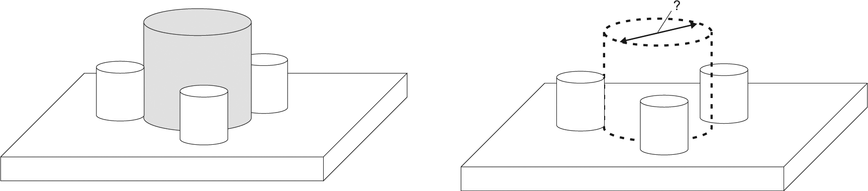
Extension to size specification. How might the function on the left be captured when tolerancing the pins (shown at right)?.
Features of size
In the world of ISO GPS, the specification of size is limited to features of size. Historically (in both ISO and ASME), these features of size have been limited to spherical and cylindrical surfaces, and pairs of opposing parallel planes. ISO now includes wedges and cones as features of size, 8 and Srinivasan 9 discusses the family of quadrics that support this addition to the feature of size “family.” In addition, the symmetry classes covered by these features of size are described, which influences their use as datum features. Each of these features of size has the geometric characteristic that it is Shape-Invariant under Offsetting (SIO). This concept, introduced by Voelcker and Sabin and reported by Voelcker, 5 describes those objects for which offsetting of the object boundary has the same effect as a scaling operation. For example, taking a cylindrical shell with diameter of 10 units and offsetting this boundary outward by 1 unit will result in a cylindrical shell of diameter of 12 units; scaling the original cylindrical surface by a factor of 1.2 would result in the same final surface. This shape invariance under offsetting is more than a geometric curiosity; it is a result of some desirable design properties outlined in the next section.
Properties of features of size
There are two basic properties that have historically been applicable to size tolerances. First, the size of a nominal feature is characterized by a single parameter. While this might be a diameter or distance, a single size tolerance will not be used to control both the height and width of a feature simultaneously. Second, containment is maintained monotonically for this size parameter, that is, a nominal (perfect form) feature with a size of λ will “fit inside” a nominal feature with a size of λ + ε, where ε can be arbitrarily small. These properties can be derived from the SIO property where a single parameter can represent the scale of the feature, and the scaled shapes will satisfy the property of fitting inside one another. The “under offsetting” property will ensure that two identical shapes of different sizes will have the same clearance between them around the entire boundary of the features.
This is a useful design tool when applying tolerances to guarantee assembly of rigid components—if an opening is required to be larger than size X, then a mating part that is smaller than size X will always be able to fit into the opening. Complementary specifications observing this rule are frequently used in tolerancing for assembly.
Extensions to size
Although the assembly of rigid components is a classic and important design problem, there are other functional requirements that might have us think about size differently. Many industrial components have tolerances that are tight enough that the assumption of rigidity is no longer valid—with tolerances of a few micrometers, the deformation of many industrial materials is of the same order of magnitude. A round, household plastic container provides a compelling domestic example. The inner circumference of the lid and the outer circumference of the container that comes into contact with the lid should be toleranced carefully to ensure an airtight closing. These objects are not easily stretchable and maintain good integrity of their circumference, whereas their flexibility renders their diameter to vary even under normal conditions. Concerning additional (nonassembly) applications, the circumference of a feature may also be of importance if this feature rolls on another feature or surface. In all these cases, instead of indirectly controlling the circumference using a linear size tolerance, it may be more effective to place the geometric control directly on the characteristic that is important (namely, the circumference). A similar situation can be envisioned if the volume of a tank or displacement of a solid is part of the primary function of a part or feature.
Another area where additional specification tools are needed is when mating parts do not have the same nominal geometry. For instance, we may wish to capture the end of a shaft within a nest of rigid fingers, or pins, as shown in Figure 5. While it has been possible for many years to control the location and size of a pattern of pins, the control of the inner diameter constrained by contact with the pin surfaces is far more difficult to control directly. The standard tools used to ensure that a set of pins will fit within a set of holes (such as mounting a wheel to the hub of an automobile) will not provide very good control over the cylinder that is inscribed within the set of pins.
The extensions to size that have been introduced in the tolerancing standards are described in the following section. While the properties of monotonic containment may not be required explicitly by the ASME Y14.5-2009 standard, there is evidence that this desirable trait will be maintained, even with the extensions described in the following.
Standards for size tolerancing
ISO has popularized the notion of “limits and fits” where the tolerance values are indicated only symbolically; for example, an indication of 16 h7 in the specification means
The main standards that will be discussed here with respect to size tolerances are ASME Y14.5-2009 3 and ISO 14405-1:2010. 4 As described in section “Traditional size tolerancing and the Taylor principle,” there are two major default interpretations of ± size limits in geometric tolerancing: (1) ASME Y14.5 Rule #1, also known as the Taylor principle, that requires two-point measurements and envelope requirement, and (2) ISO 8015 (which defines the terminology and fundamental concepts used in ISO 14405 and other ISO GPS standards) that specifies a default of two-point measurements. Regardless of the tolerancing system used, the envelope requirement implies a perfect form at the MMC—thus coupling the notions of size and form. With the envelope requirement, the parameter of interest is the size of the mating perfect form envelope, and deviations away from this envelope will not cause the envelope size to change. The extent of form deviation allowed is captured by the other (upper or lower) size limit where any form deviation will have an effect on the local two-point size.
Two types of extensions to the conventional envelope and two-point specification methods above have been recently introduced by standards. The first is the expansion of the class of features of size to objects that do not easily conform to the single parameter quantification of the classic features of size. This is manifest in the ASME Y14.5:2009 standard 3 under the name of irregular features of size. The second extension is in the specification of the size based on new analysis methods for the data extracted from an actual, imperfect part feature. By giving the designer the freedom to specify the way in which the size parameter is defined, it is envisioned that the design intent can be more closely captured than with traditional association methods. A set of 14 new specification modifiers appear in ISO 14405-1:2010. 4
ASME extensions to size
The main changes to size specification in ASME Y14.5:2009 are in the introduction of irregular features of size. These are categorized further into those features that contain (or are contained in) an envelope that is one of the classic features of size (e.g. sphere, cylinder, and parallel planes) and those which are related to an envelope of some other shape. The first type of irregular feature of size is shown in Figure 5, where the pins contain a cylindrical envelope from which a size value is induced. The second type of irregular feature of size might be an irregular surface profile. One might ask why it is important to classify these irregular shapes as features of size, rather than allow them to remain as simple profiles. The main reasons are to permit location tolerancing of these features with material condition modifiers (i.e. additional positional variation is permitted as the feature changes size) and also to use the features as datums, again with material condition (material boundary, in Y14.5 terms) modifiers. To clarify, the benefit of this extension to the class of features of size is not directly in the control of the feature, but in the use of the feature’s “size” to permit additional variation in other tolerances or mobility in datum reference frames.
ISO extensions to size
The release of ISO 14405-1:2010 is a major development in the definition of linear size tolerances. It defines 14 types of linear size tolerances, as shown in Table 2, for cylindrical and two parallel planes features. The first two (LP and LS) are explicitly local in their interpretation, while the next three (GG, GX, and GN) can be applied globally to the entire feature. Of the three calculated sizes, CC and CA are local (cross-sectional), while CV is global. The final six tolerance symbols are applied to populations of values (two point, by default, but other methods may be specified) obtained from a feature. These symbols provide a vast array of methods for specifying feature sizes.
ISO 14405-1:2010 specification modifiers for linear size.
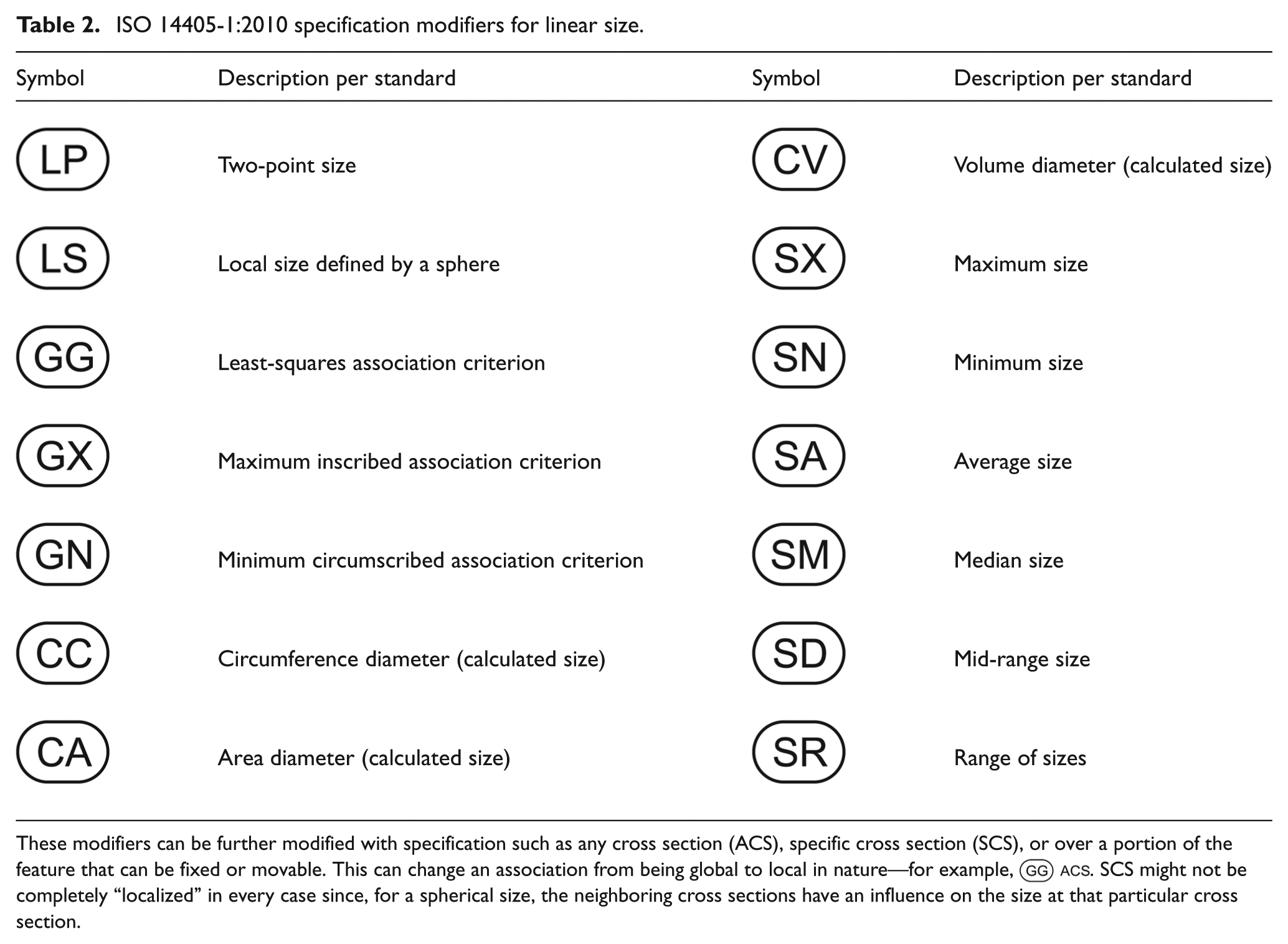
These modifiers can be further modified with specification such as any cross section (ACS), specific cross section (SCS), or over a portion of the feature that can be fixed or movable. This can change an association from being global to local in nature—for example,  . SCS might not be completely “localized” in every case since, for a spherical size, the neighboring cross sections have an influence on the size at that particular cross section.
The introduction of these new linear size tolerancing symbols and their modifiers gives rise to an interesting emergence of size tolerancing algebra. In simple cases, it is easy to see that the combination of LP (for the lower size limit) and GN (for the upper size limit) is equivalent to the ASME Rule 1 for solid cylindrical features, but the combination of LP and GX for the same solid cylindrical feature poses an interesting question—should this be forbidden or be allowed to enable the designer to ensure that there is some “bulk” in the solid cylinder? Such rules for combination have not yet been developed.
An example of how this specification might appear on a drawing is shown in Figure 6. In this case, the specification of GG controls the association of the actual surface feature in the determination of conformance to specification.
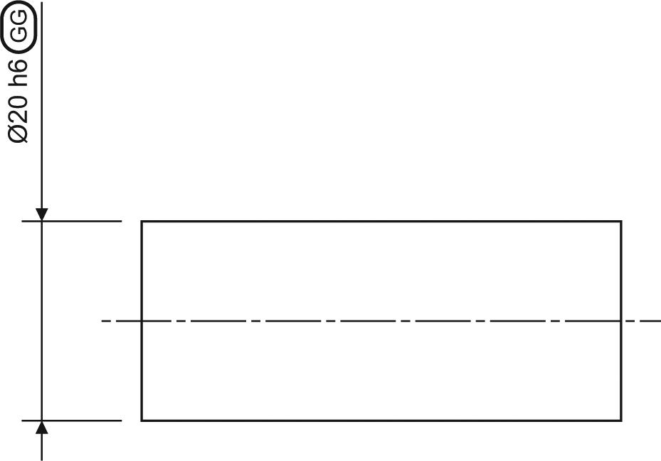
Specification of a feature of size using the Gaussian (least-squares) association criterion.
Uses and implications
The uses of these new size specifications and the implication of having the symbols available to designers are of real interest, both to the design community and to those who must inspect the features to determine conformance to the tolerances specified. Prior to the introduction of these new symbols, there were aspects of functional specification that were not easily captured with the standard syntax of the tolerancing standards. This is represented graphically in Figure 7(a), where the rectangle representing standardized controls does not cover all the geometric configurations that are needed for function (e.g. circumference of a roller and area of a conductor cross section). In Figure 7(b), we show how the state of affairs may have changed. In using the new standards, there are many more things that can be specified; however, it is unclear what fraction of these specifications is addressing the area of functional control that is desired. The figure also attempts to draw attention to the necessarily regular structure of standardized specifications (hence the rectangular regions) and to recognize that the occasional use of nonstandard specification methods may be needed to ensure the appropriate geometric control for specialized functional requirements.
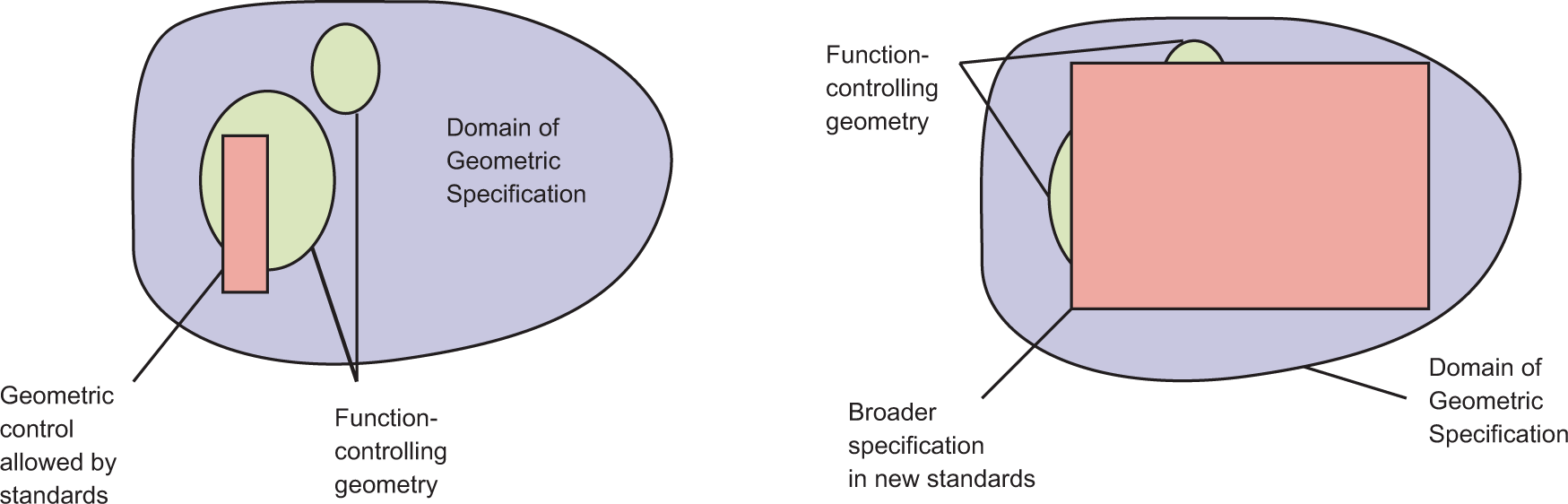
Schematic representation of functional coverage of geometric standards, (a) before and (b) after the introduction of recent documents.
At the moment, we can propose that the new specifications may be of use to some plastic and rolling bearing manufacturers and in industries that have other rolling components. In addition, industries where volume is measured for dispensing chemicals, medicines, or other product may specify containers and dispensers using this new syntax. If a product’s raw material is very expensive, molded or forged parts might also have a volume-limiting requirement—if not for function, for controlling the cost of materials.
The case of roller bearings brings us to a final interesting question: while an individual roller may be specified by its circumference or average size or some other size specification, the performance of the assembled bearing is critically linked to the nature of the entire set of rollers that are used in the assembly. The interaction of rank ordering of size values on individual components, combined with the use of population characteristics (statistical tolerancing) on the population of parts, is a matter for further study, as these may ultimately converge to a single functional specification if the designers can determine what is required.
Open issues
The specification operators defined in the ISO 14405-1:2010 standard provide mechanisms that expand the domain of possible size specifications. What remains unclear is how specific desired functional requirements are represented within this domain. As also discussed in section “Uses and implications,” there are interesting issues surrounding the use of population characteristics and their interaction with the specifications that classify size based on order statistics within an individual feature.
The verification of size specified according to ISO 14405-1 can be viewed using the same conceptual separation as is expressed in the specification: global, calculated, and statistical. However, additional issues surround the specifics of the verification of tolerances that are specified with this new syntax. Coordinate metrology has long wrestled with the issue of how many points to measure in order to adequately represent the part surface. This question is also present for the rank-ordering specifications: not only does the inspector need to decide how many points are suitable at a given cross section, the number of cross sections needed to determine a median value (for example) must also be chosen. Also, for volume-based size specification, the inclusion (or omission) of “end surfaces,” which are traditionally not part of a feature of size, must be addressed.
At present, there exists no formal method to ensure that a specific physical inspection technique conforms to a specific size modifier, and no validation of the algorithms that operate on sampled coordinate data to determine conformance to specifications (with the exception of some least-squares testing). While the theoretical answer may be clear for some of these validation methods, the estimation of task-specific measurement uncertainty for determining conformance to these specifications will be a challenge for years to come.
Summary
The increased richness of size specification in the recently released standards opens a much larger domain of specification for the designer. There are some specifications that, while syntactically valid, may not correspond to a functional requirement that can be envisioned today. It is hoped that this wider array of tools will be judiciously used by designers to more closely capture the functional requirements of their designs.
With the publication of these new tolerancing standards, the use of these tools in industry may reveal new avenues of functional size specification that have not been mentioned here. Future study remains in pursuing functional specifications that will allow more effective, succinct use of GPS. In addition, the interaction of within-part and part-to-part specifications is an area where much is still to be learned.
Footnotes
Acknowledgements
The authors thank Professor Herb Voelcker for his insights regarding the subtle nature of size control in mechanical design and his leadership toward a careful evaluation of size specifications. The authors would also like to thank the members of national and international standards bodies who have spent many years in developing the principles that underlie geometric tolerancing specifications, Joshua Lubell for his insightful and constructive comments on the manuscript, and Tom Charlton for his thoughts on applications for global size tolerances. Any mention of commercial products within this article is for information only; it does not imply recommendation or endorsement by NIST.
Funding
The first author’s research was funded in part by a grant from NIST, grant number is 60NANB11D166.