
Abstract
The original Johnson–Cook equation fails to describe the significant thermal softening phenomenon of flow stress in cutting process of titanium alloy Ti6Al4V. Recently, some researchers developed some modified Johnson–Cook models of Ti6Al4V by introducing some additional parameters. But effective parameter identification method is unavailable in those research works. In this work, an inverse approach is developed to determine the additional parameters. A modified Johnson–Cook model with the hyperbolic tangent function is adopted, in which four unknown parameters need to be determined. The parameter assessment is taken as an optimization process based on the unequal division parallel-sided shear zone model. Along with the measured cutting force and chip thickness, the firefly algorithm is introduced to search for the parametric optimal solution. Those four parameters are determined when the difference between the predicted and experimental effective stress at shear plane reaches its minimum. The identified constitutive model is subsequently verified by finite element simulation of orthogonal cutting process, and compared with previous different material models. With the identified modified Johnson–Cook model, the serrated chip is observed in all the simulations. A good agreement between verification experiments and simulations is achieved. An acceptable prediction accuracy with an error of 10.28% on cutting force and an error of 18.12% on chip size is achieved.
Introduction
Ti6Al4V is a titanium alloy that is most commonly used in the aerospace industry. However, its poor machinability is a perennial problem due to the low thermal conductivity, low elastic modulus, and high chemical reactivity. The poor heat transfer performance induces heat accumulation in the primary zone, which produces localization of shear plastic deformation. Therefore, the chips are usually found to be serrated in cutting Ti6Al4V. Low thermal conductivity also gives rise to very high temperature at the contact zone. It produces a very complicated physical and chemical interaction between cutter and workpiece, which accelerates the tool wear and increases cutting forces. In addition, low elastic modulus and cyclical serrated chip formation lead to rapid cutter wear and poor surface integrity.
In order to avoid expensive cutting experiment, especially for residual stress measurement, finite element simulation of cutting process is usually employed to predict cutting performance and optimize process parameters.1,2 A roadblock for numerical modeling of cutting process is the plastic constitutive model of Ti6Al4V at large strain, high strain rate, and high temperature. A plenty of empirical statistical models were proposed by the previous researchers, including the Johnson–Cook (JC) model, power law model, and Zerilli–Armstrong (Z-A) model, and so on.3–6 Among these models, the JC model is one of the most commonly used plastic constitutive models for machining. The traditional approach to determine the model parameters is the high-speed compression test, such as the split Hopkinson pressure bar (SHPB) test. However, it needs a lot of experiments to obtain a high fitting precision, which leads to a high economic efficiency and time-consuming cost. Furthermore, another fatal flaw of this approach is the limited range of strain/strain rate. The available maximum strain and strain rate are about 0.6 and in the order of
To describe the flow stress softening phenomenon, some researchers recently improved these classical material models for Ti6Al4V. Combining the strengths of JC model and Z-A model, Che et al. 16 proposed an integrated model simultaneously including the coupled effects of strain, strain rate, and temperature. Kizhakken and Mathew 17 improved the prediction accuracy of burr thickness for micro-end milling of Ti6Al4V by including machining temperature into the hyperbolic tangent material model. Considering the temperature-dependent dynamic recrystallization, Huang et al. 18 improved the JC model by coupling the effects of the critical strain and temperature on flow stress softening of titanium alloy Ti6Al4V in cutting process. Similarly, Calamaz et al. 19 proposed an improved JC model of titanium alloy Ti6Al4V. The main feature of the empirical model is to add a new term into the original equation with the hyperbolic tangent function. In this model, the strain softening phenomenon is captured. In addition, they subsequently made a further improvement by incorporating the temperature and strain rate effect.20,21 Sima and Özel 13 reviewed the modified JC model and developed an improved temperature-dependent flow softening model. They claimed that the thermal softening effect is stronger than the strain hardening effect, and the strain rate sensitivity will decline with the increase in strain. Based on the work of Calamaz and Sima, Liu et al. 14 built an enhanced Z-A model of Ti6Al4V by introducing a failure function. They linked the loss of material load resistance to the void and crack formation and the dynamic recovery. The adiabatic shear band formation in cutting process is accurately simulated using the enhanced constitutive model. Karpat 22 also proposed an improved material model of Ti6Al4V based on micromechanical constitutive model developed by Yen, Jain and Altan. 23 He added an additional term similar to Calamaz’s model into the existing model to describe the strain softening phenomenon at high strain. The effect of softening parameters on the simulated cutting forces and chip thickness were subsequently studied. Then, the optimum additional parameters were determined by single factor method. To describe the material response of Ti6Al4V above the recrystallization temperature, Andrade et al. 24 introduced a new term to the original JC equation. But the model is limited to a low strain range. Liu et al. 7 subsequently expanded the scope of application to higher strain range using a strain-based piecewise function. Simultaneously, they also built another similar piecewise constitutive equation of Ti6Al4V. 8 The latter differs from the former by considering the recrystallization temperature as the demarcation point. All the above models except Andrade adopted a new additional term called the hyperbolic tangent function. It is due to its quality that the large slope locates the middle region and there is almost no slope in both the two side regions. It maintains the flow stress to be identical at low strain after modifying, but reduces the flow stress to an almost constant low value at high strain after the critical point. These research works showed that the hyperbolic tangent function can perfectly accomplish the task of capturing flow stress softening of Ti6Al4V. However, there is a legacy issue on determining the modified parameters. The previous studies determined these parameters by single factor screening approach or simple search algorithm.13,14 Obviously, these methods are too simple to guarantee in obtaining the optimal parameter combination.
Inverse approach based on evolutionary algorithm may be an effective way to determine material constitutive equation. Based on the finite element analysis, Ren et al. 25 inversely determined the constitutive equation of titanium alloy Ti6Al4V for orthogonal cutting. Linjiang et al. 26 conducted similar work on another material—Ti2AlNb intermetallic alloys. With inverse identification method, Chen et al. 27 determined Al6063 constitutive model for cutting process based on the quasi-static compression, orthogonal cutting, and cutting simulation. Above-mentioned research works need to conduct lots of time-consuming simulations. Laakso and Niemi 28 developed a method to determine material model parameters from orthogonal cutting experiments using the extended Oxley’s shear zone theory.
The purpose of this article is to determine the modified constitutive parameters by a reverse approach based on firefly algorithm (FA) and shear zone model. The remainder of this work is organized as following. In section “Constructive model,” a modified flow softening model of Ti6Al4V is introduced based on Calamaz’s model. The effect of modified parameters on flow stress is then analyzed. Section “Inverse identification approach” subsequently presents the inverse approach for determining modified constitutive parameters. The unequal division parallel-sided shear zone (UDPSSZ) model, which is developed in our previous research, and the FA are employed in this method. 29 Based on the proposed inverse approach, the modified parameters are determined using the orthogonal cutting experiments in section “Determination of modified JC parameters.” And, the two-dimensional (2D) finite element model of orthogonal cutting Ti6Al4V is built using finite element software DEFORM-2D. Then, the simulated cutting forces for different material models are compared with the measured data. Finally, this article concludes with a summary of this work in section “Conclusion.”
Constitutive model
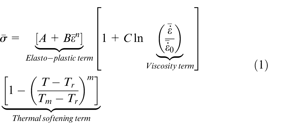
The JC equation is extensively adopted to evaluate the flow stress at a wide range of strain, strain rate, and temperature, especially for machining. It simultaneously includes the influence of strain, strain rate, and temperature, but does not consider their coupling effect. The original JC equation is defined as a combination of three functions
where
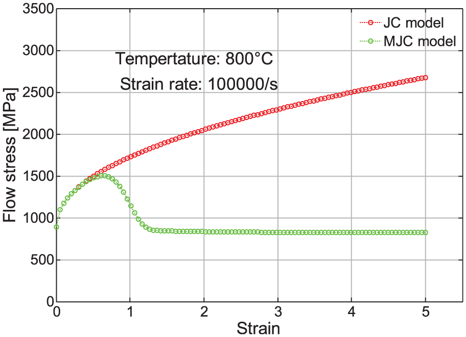
Figure 1 shows that the flow stress rises with increase in the strain. As mentioned above, the microcrack, thermal softening, and dynamic recrystallization will give rise to the obvious flow softening in cutting process. Therefore, some researchers improved the original JC material models to describe this material behavior. Among these models, a typical representative is Calamaz’s model.19–21 They considered the critical strain value as the watershed between strain hardening and flow softening. In this article, a similar modified material model is developed based on the previous work and is given in equation (2)
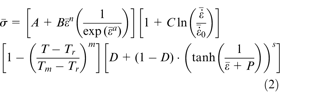
where
where a, b, d, and s are the positive material constants.
Stress–strain relation of titanium alloy Ti6Al4V.
The exponential function is added into the first term to reflect flow softening phenomenon at large strain caused by the microcrack in chip. The fourth term is used to describe the flow softening behavior induced by the temperature rise. Figure 1 shows the original and modified JC constitutive equations. It can be observed that the modified curve almost coincided with the original curve when the strain is less than about 0.6. Then, the modified flow stress has a large decline when the strain ranges from 0.6 to 1.2. At the high strain region, the modified model outputs an almost constant low stress while the original model still produces a continuous increase in stress. It should be noted that the high strain is very difficult to obtain by the SHPB test due to the limitation of the impact speed. However, the strain in cutting process usually reaches to 5, or even larger.
Figure 2 presents the effect of modified parameters on the flow stress. For all the curves, the five original JC parameters are from Lee’s data based on the SHPB test (A = 724.7, B = 683.1, C = 0.035, m = 1.0, n = 0.47, Tr = 20 °C, Tm = 1604 °C, and
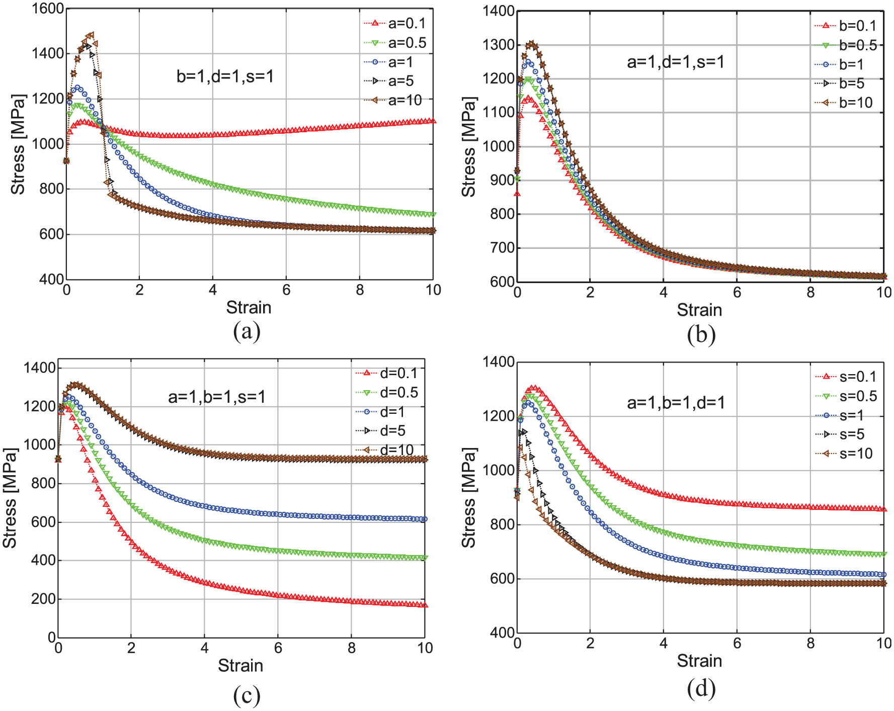
Effect of modified parameters on flow stress: (a) parameter a, (b) parameter b, (c) parameter d, and (d) parameter s.
Inverse identification approach
UDPSSZ
Figure 3 displays the unequal division primary shear zone model of 2D cutting. The cutting speed is v and the rake angle is α. Symbols tc and tu represent the chip thickness and the undeformed chip thickness (UCT), respectively. The plastic deformation is limited in the zone between the CD and EF. CD is the inlet boundary and EF is the outlet boundary. Both the boundaries are supposed to be parallel to AB.
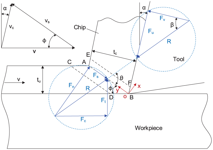
Orthogonal cutting model with an unequal division shear zone.
According to equation (4), the shear force

where
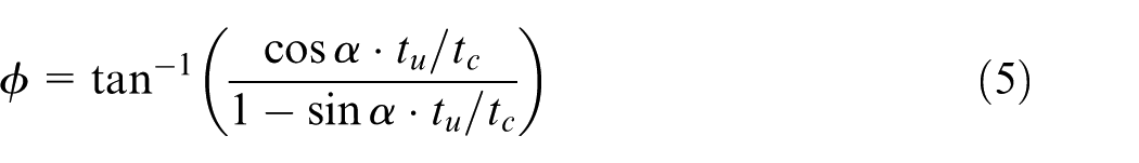
Equation (5) presents the expression of shear angle
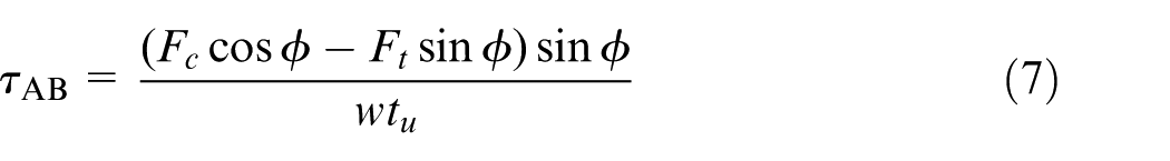
The shear stress can be expressed by equation (6)
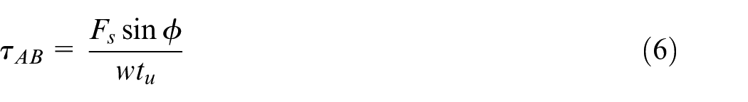
where w is cutting width.
Substituting
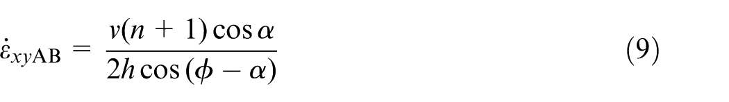
In the UDPSSZ model, 29 the strain rate distribution of the primary shear zone can be calculated by equation (8)
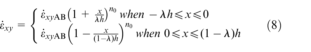
where
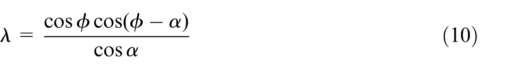
The
Pan et al. gives the expression of the ratio
From Shi et al.’s study, 31 the thickness of shear zone can be expressed by equation (11)
where
The shear strain of shear zone can be obtained by integrating the shear strain rate with respect to time, as shown in equation (12)
where
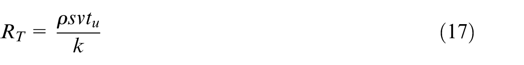
In this article, Boothroyd’s 33 cutting temperature equation is adopted to calculate the temperature rise of the shear plane, as shown in equation (14)

where
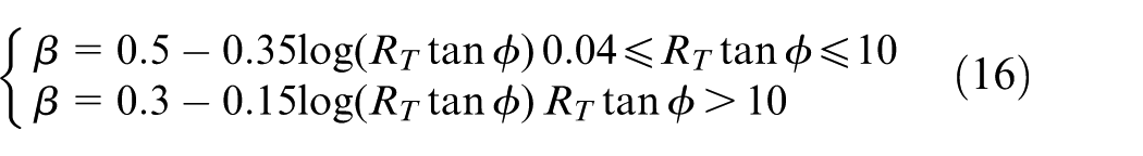
According to Boothroyd’s theory, the temperature rise is expressed by equation (15) 34
where
where
where
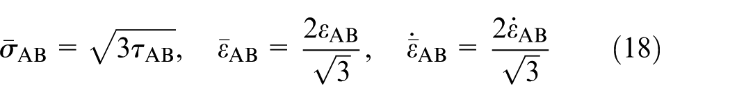
From the analysis above, the equivalent stress, strain, and strain rate can be calculated by equation (18) with Mises yield criterion
FA
Xinshe Yang developed the FA from the firefly’s behavior, which is a nature-inspired metaheuristic algorithm.35–37 He gives three rules for the FA: (1) fireflies attract each other regardless of their sex, (2) attractiveness is proportional to the brightness, and they both decrease as their distance increases, and (3) the brightness is determined by the objective function.
Taking the maximum optimization problem as an example, brightness
where
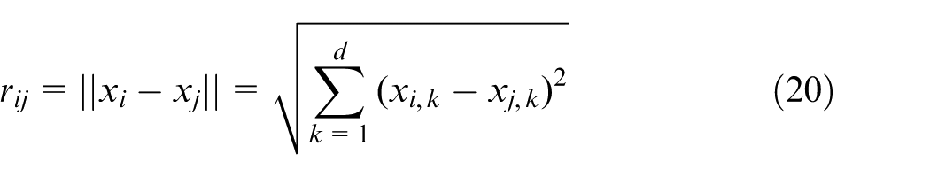
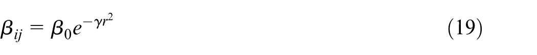
where xi, k is kth component of the spatial coordinate xi of the ith firefly. Firefly updates its location by equation (21)
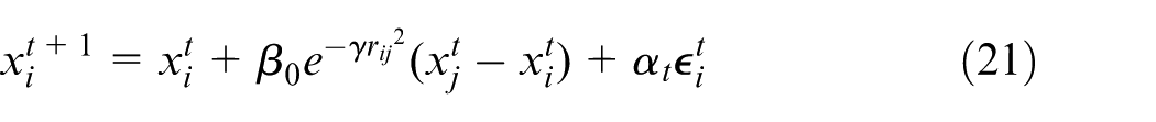
where the first term is the location of ith firefly at the previous iteration,
where

where
Optimization routine
In the current research, there are four modified parameters a, b, d, and s to be determined. And, an inverse approach is developed to identify the parameters. This algorithm takes experimental cutting force and chip thickness as the input parameters. Based on the UDPSSZ model, equivalent stress, equivalent strain, equivalent strain rate, and temperature of the primary shear plane can be obtained with these measured data. One minimization optimization technology is introduced to determine the modified parameters. The four parameters, a, b, d, and s, approach gradually their optimal value when the error of the equivalent stress gets smaller. The established optimization model is presented in equation (24). And, the optimization process is described in Figure 4. The FA is adopted to search for the optimal solution
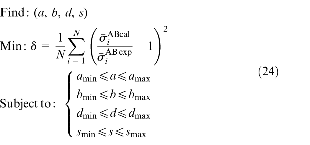
where N is number of cutting experiments,
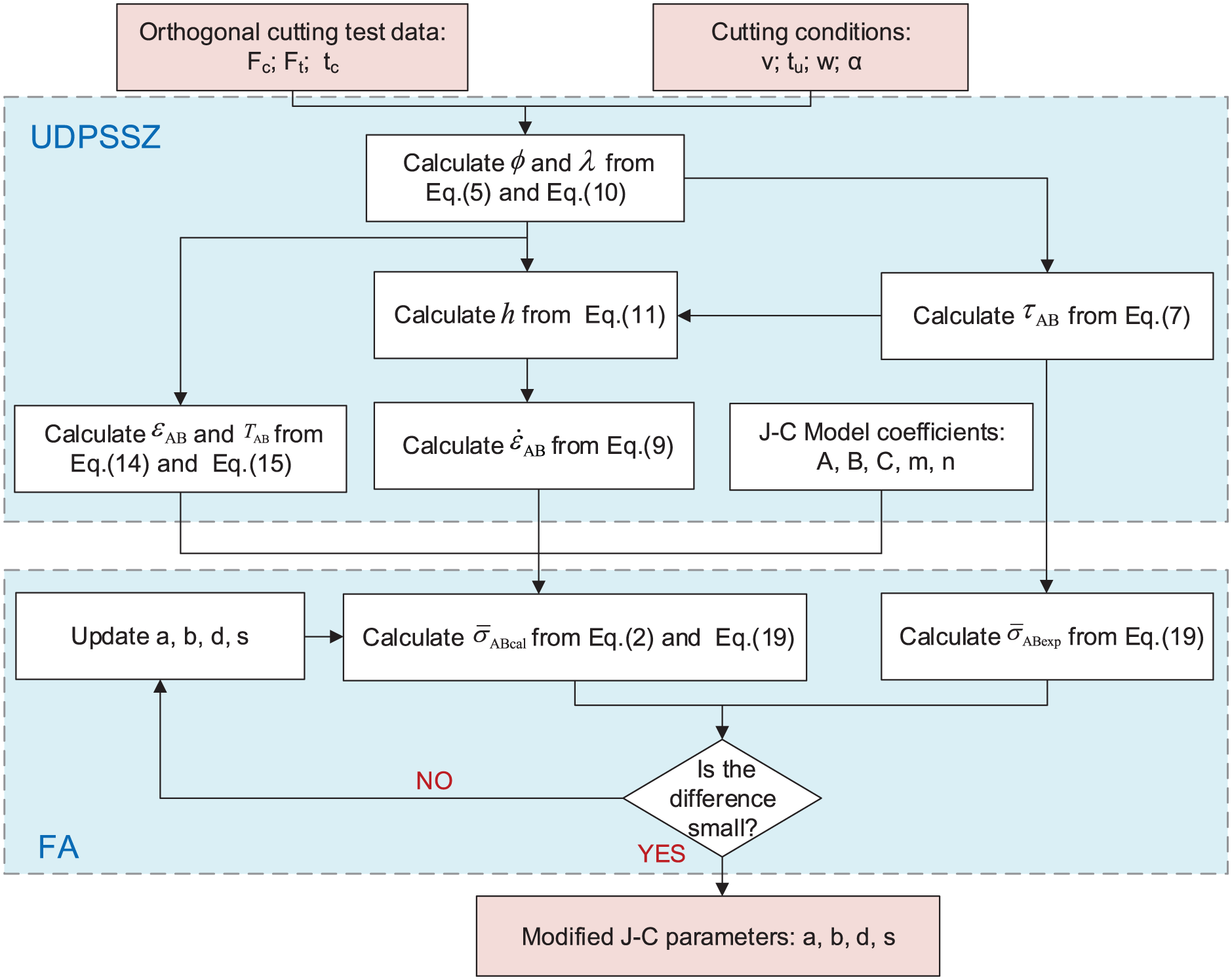
Flowchart for determining the modified JC parameters.
Determination of modified JC parameters
Orthogonal cutting experiment
A total of 24 experiments of turning Ti6Al4V are conducted on HK63, three-axes, machine without cutting fluid. The commercial coated carbide cutting inserts (SECO-LCMF-160404-0400-FT, CP500, SECO Co., Ltd.) are used. And, a left-hand cutter holder is used to fix inserts. A new cutting edge for each experiment is used to avoid the effect of cutting edge wear. The cutting rake angle, relief angle, and edge radius are 12.62°, 7.36°, and 30 µm, respectively. The measurement detail is available in Zhou et al. 29 The workpiece is a cylinder of titanium alloy Ti6Al4V with diameter of 94 mm and length of 350 mm. The workpiece is pre-grooved out some bosses with 2.0 mm width for orthogonal cutting, as shown in Figure 5. In the experiment, the cutting force test system includes the Kistler force dynamometer (type 9257B, Kistler Co. Ltd.), Kistler multi-channel charge amplifier (type 5080A, Kistler Co. Ltd.), dynamic data acquisition and processing system (Strtust STG), and data processing software (DEWEsoftx7.1, DEWESoft Co. Ltd.). Stable cutting force signal data are averaged and taken as the cutting force result. Some chips are saved after each cutting experiment, and their thickness is measured with a micrometer. An average value of five measurements in different locations is taken as the chip thickness.
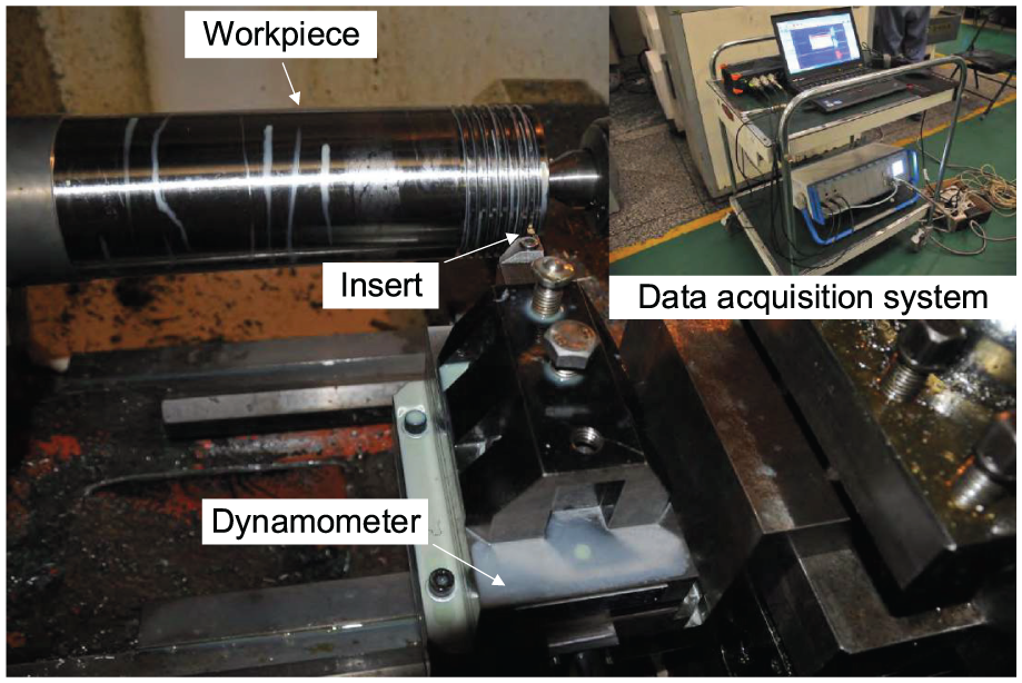
Experimental setup of the orthogonal cutting Ti6Al4V.
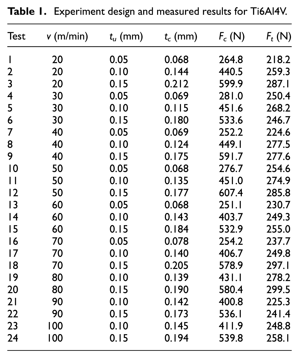
There are two design factors in the experiment, including cutting speed and UCT. A single factor experiment with two factors is employed in the current work. The cutting speed ranges from 20 to 100 m/min when the UCT changes from 0.05 to 0.15 mm. Table 1 shows the factor design scheme and the measured results, including the thickness of chips, main cutting forces, and trust forces. Three experimental data in high cutting speed range are deleted due to large test error. All the 24 tests are used to calculate the modified JC parameters. Three experiments with different cutting speeds and UCT including No. 11, No. 20, and one additional experiment are taken as the verification experiments. The chip topography and size are measured with the form and roughness measurement instrument InfiniteFocus G4 (made by Alicona Co., Ltd). The measured cutting forces and chip size of those three experiments are simultaneously used as the verification data.
Experiment design and measured results for Ti6Al4V.
Optimized result and discussion
Optimized result
The inverse determining process of the four parameters is executed on MATLAB 2012a software platform. In the current work, the algorithm parameters are set as follows: the attractiveness
The developed inverse approach is implemented in a 64-bit win7 system with an Intel® Core™ i5-4590 CPU with 3.30-GHz processor. Figure 6 shows the iterative process of the FA. It is confirmed that the FA has the ability to achieve convergence. After about 50 generations, the optimized solution converges to the final error (about 14.519%). It indicates that that the predicted equivalent stress agrees well to the measured results. Although adopting a large population size, the developed MATLAB program still does not lose computing efficiency due to the high efficiency of the FA. With the termination criterion defined by equation (24), the global optimum solution is found within 50 generations and only 14.428 s is taken to accomplish the whole search process.
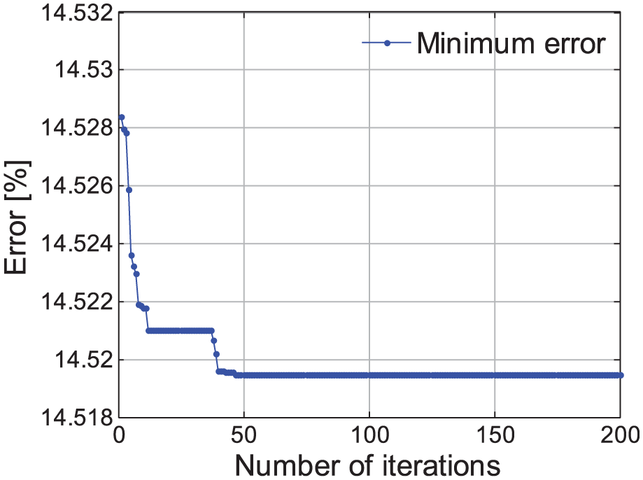
Error of the best result for each generation.
The optimized result is a = 2.872, b = 4.678, d = 9.843, and s = 0.001. Therefore, the modified JC model for Ti6Al4V can be expressed as follows
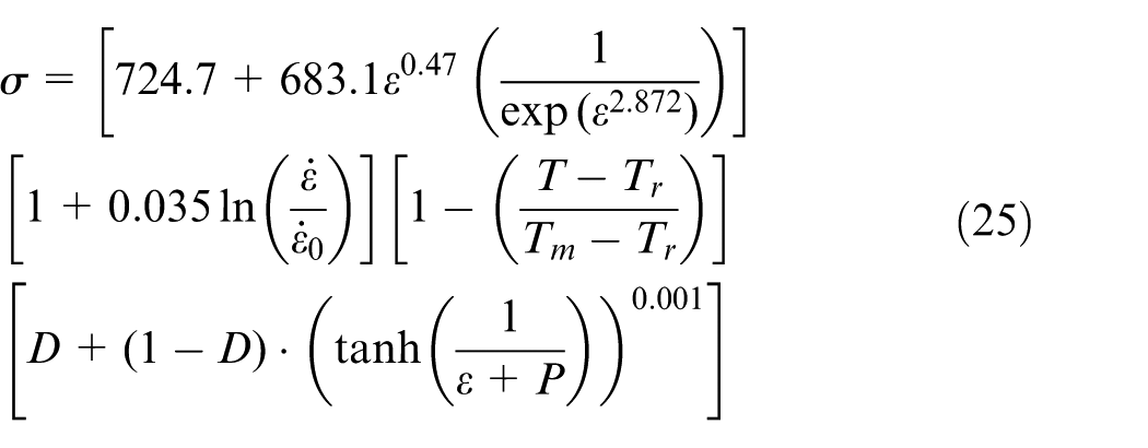
where
Discussion on uniqueness of optimized solution
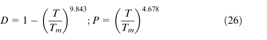
The inverse engineering generally suffers the major limitation with the uniqueness of the optimized parameters. The inverse identification of the JC constitutive parameters may export several solutions due to the high non-linear relationship between the input and output variables.31,38 In this work, the developed MATLAB code is executed five times with different initial guesses of the material parameters. And, the obtained optimized solutions are listed in Table 2. Similar fitting error of about 14.52% is achieved. It should be noted that overmatch between the experiment and the calculation does not benefit due to the fact of measured error. It can be seen that the material parameters b and d present some differences, while the material parameters a and s are unique. In fact, the effect of parameter a beyond 3.899 on stress–strain curve is very limited according to the stress–strain curve. It can be also seen that material parameter has little effect on flow stress when its value is beyond five from section “Constructive model.” Therefore, the different levels of combination of those two parameters probably yield similar optimal solutions as shown in Table 2. It can be found that the five solutions correspond to the same flow stress curve as shown in Figure 7. All the solutions show that the flow stress has a large decline at the high strain region. Now that no difference is found in the different solutions, the first material parameters are used for the following finite element modeling (FEM).
Optimized solutions with different initializations.
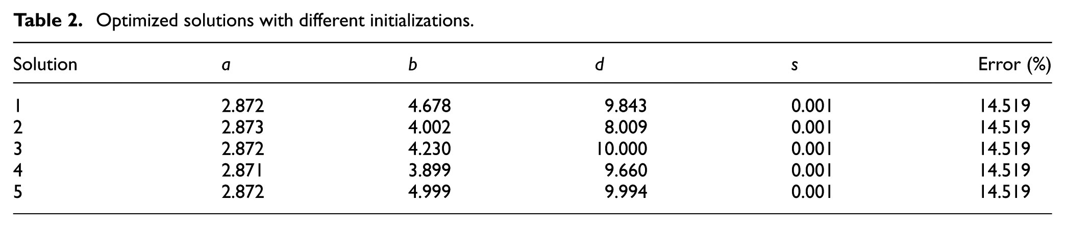
Stress–strain curve for five different solutions.
Verification
Numerical model
To verify the effectiveness of the determined modified JC model, a 2D finite element model of turning Ti6Al4V is developed in DEFORM-2D V10.2 platform. DEFORM employs auto-updated Lagrangian formulation. It has so robust remesh capability that neighboring grid density of cutter tip is high enough to catch the larger deformation in cutting process.
31
The orthogonal cutting process with thermo-mechanical effect is analyzed based on the assumption of plane strain. The cutter and the workpiece are modeled as an elastic body and elasto-plastic material, respectively. The cutter geometry is accordingly defined by a rake angle of 12.76°, a relief angle of 7.22°, and a cutting edge radius of
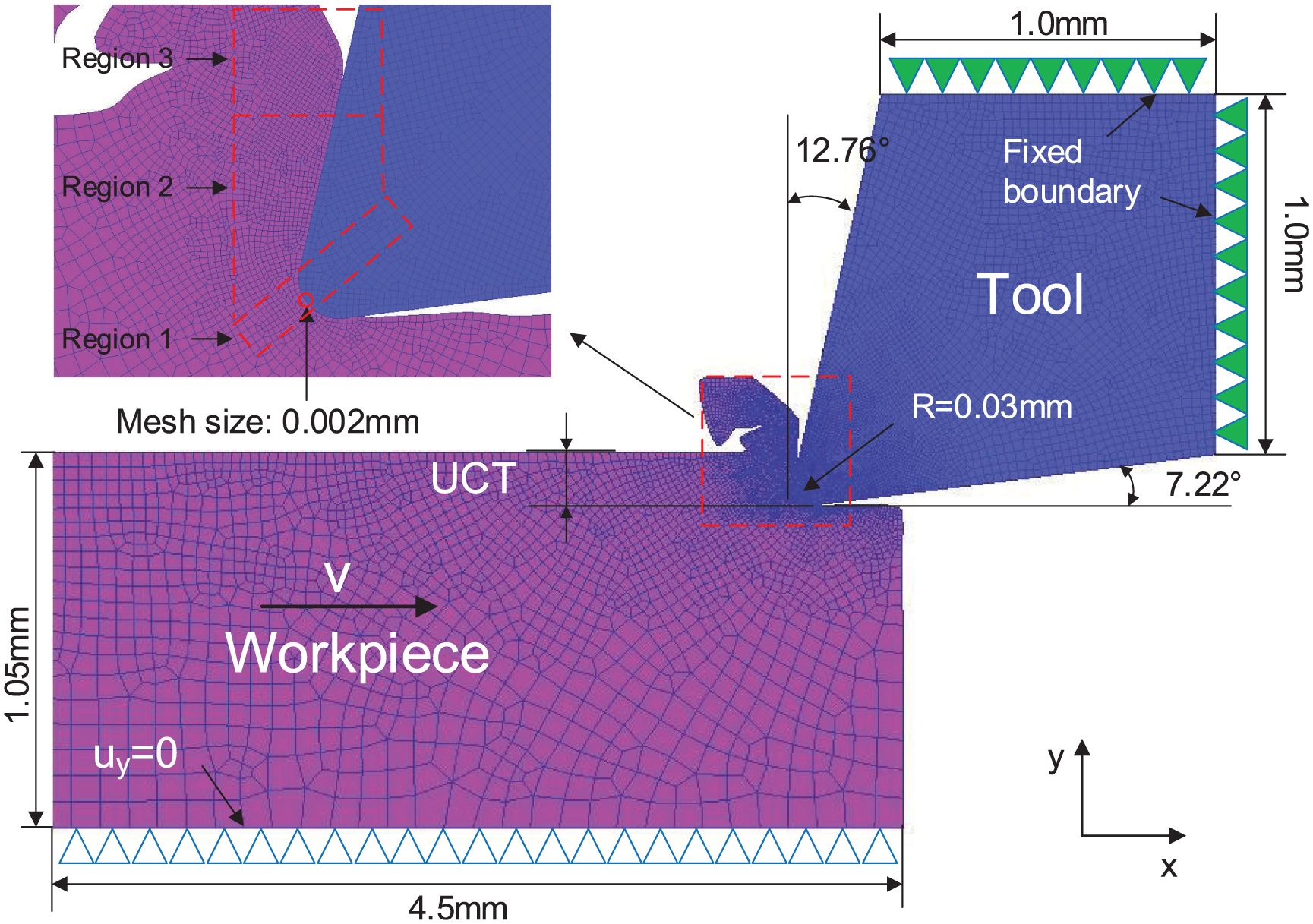
FEM model for orthogonal cutting Inconel 718.
There are two contact models for modeling the contact behavior between cutter and workpiece in machining process, Coulomb contact model and shear contact model. Shear model is commonly employed under severe contact condition, while Coulomb model is used to describe mild contact behavior
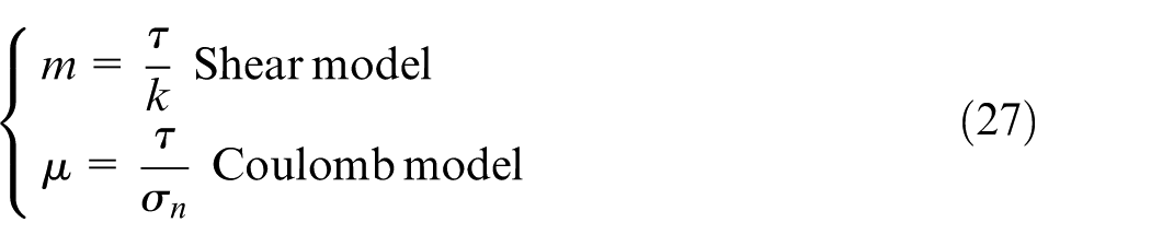
where
The friction between cutter and workpiece is defined with three segregated contact regions.14,22 As shown in Figure 8, a shear model with a high friction coefficient (m = 1) is used for the sticking region from the cutter tip to the point of tangency between cutter and workpiece. A fixed shear friction coefficient of 0.85 is used to describe the rubbing behavior between cutter and workpiece in the region from the tangency point to the uncut chip thickness boundary. The rest region of the rake face has a moderate contact behavior with chip. And, a Coulomb coefficient of 0.5 is adequate to describe the sliding contact condition. A very large heat transfer coefficient (h = 1000 W/m2 k) is adopted to speed up the temperature rise process. And, it has no effect on the simulated results.
14
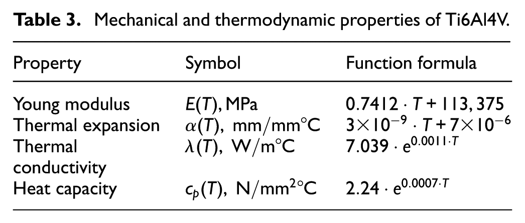
The heat convection coefficient with external environment is set as
Mechanical and thermodynamic properties of Ti6Al4V.
Three simulations with meshes of 2000, 5000, and 10,000 for workpiece are conducted to study the effect of mesh density on performance. It was found that the mesh density has no significant influence on the cutting forces when the number of mesh exceeds 2000. Figure 9 shows the simulated results. The maximum and minimum values are 249.58 and 245.01 N/mm for the main cutting force and 111.19 and 108.73 N/mm for feed force. The error induced by changing mesh number is limited by 2%. Considering both the computational accuracy and efficiency, 5000 elements are used to initially discrete the cutter and the workpiece in this work, respectively. In order to demonstrate the effectiveness of the identified modified JC model for FEM, three other modified JC models are set as the control group. The material constitutive models used in the simulation process are shown in Table 4. The model 1 is the proposed modified JC constitutive model. For the FA, 300 fireworms are initialized with random value. Therefore, one random initial material parameter is selected for the model 2. The models 3 and 4 come from the previous classical research works.14,19 It should be pointed out that there are no specified parameters a, b, and c for Calamaz’s 19 model. Therefore, similar material parameters to Sima’s model is employed for the model 3. All the modified models are input into the finite element software platform DEFORM-2D to conduct the simulations.
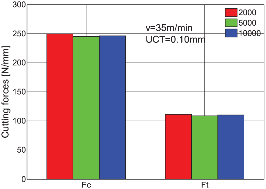
Effect of mesh density on cutting forces.
Modified JC model parameters of Ti6Al4V.
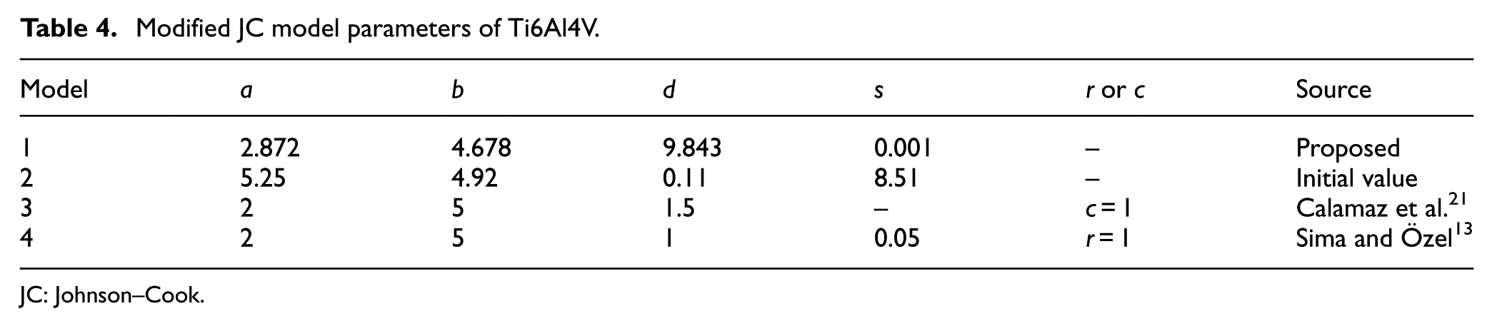
JC: Johnson–Cook
Results and discussion
As mentioned above, three experiments are employed to verify the effectiveness of the identified constitutive model of Ti6Al4V titanium alloy. Cutting parameters of the additional experiment are set as cutting speed of 85 m/min and UCT of 0.05 mm. Simultaneously adopting used and additional experiments makes the verifications complete. A total of 12 simulations with four different material constitutive models are executed on the DEFORM-2D software platform. The maximum cutting length is less than 4.5 mm. Each simulation is completed within 10 h in a 64-bit win7 system with an Intel® Core™ i5-4590 CPU with 3.30-GHz processor. The cutting force and chip size are taken as the assessment indicators for the simulations. The cutting width for orthogonal cutting is 1 mm in default in DEFORM-2D. Therefore, a half of the measured cutting force is taken as a reference value due to the different cutting widths between experiment and FEM simulation.
Figure 10 shows the measured and simulated cutting forces using the proposed modified JC model with three cutting parameters. It can be found that the predicted cutting forces agree well with the measured value. It can also be seen that the main cutting forces are more close to the measured average cutting forces than the feed forces. The prediction errors of main cutting force and feed force are 8.90% and 11.66%, respectively. For all the simulations, the predicted feed forces are slightly less than the measured value while the main cutting force is in the opposite case. When UCT equals 0.05 m/min, a better agreement with the experimental results is obtained on the main cutting forces. It can be found that there are cyclical fluctuations with large amplitude for the main cutting forces and the feed forces have smaller amplitude. In fact, this is one of the phenomena for cutting process with adiabatic shear. In adiabatic shear process, the low coefficient of heat conduction induces heat accumulation in the primary shear zone. Heat accumulation leads to a large temperature rise. According to equation (2), the modified JC model strengthens the thermal softening effect. Therefore, the flow stress will decrease with the increasing in the temperature in primary shear zone. Cutting force will accordingly decline. Smaller cutting force tends to produce less heat in turn and therefore leads to a temperature decline in primary shear zone. Then, a weakened thermal softening effect will induce the increasing of cutting force. The circulation of this process leads to the fluctuation of cutting force.
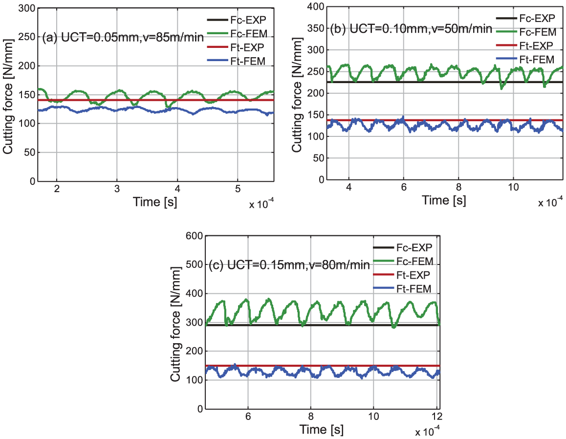
Measured average and predicted instantaneous cutting force.
Figure 11 presents the simulated and experimental chip morphology. All of the simulations and experiments produce serrated chip when feed changes from 0.05 to 0.15 mm. Adiabatic shear, which is often observed in cutting process of titanium alloy, is considered as the root cause for serrated chip. Low heat transfer coefficient of titanium alloy should be responsible for adiabatic shear phenomenon. According to the modified JC model, flow stress declines rapidly with increase in strain. It facilitates the cyclical fluctuation of cutting force as described above. Then, the temperature at shear plane also presents cyclical fluctuation. The regular serrated shape of chip is the reflection of cyclical fluctuant cutting force and temperature.
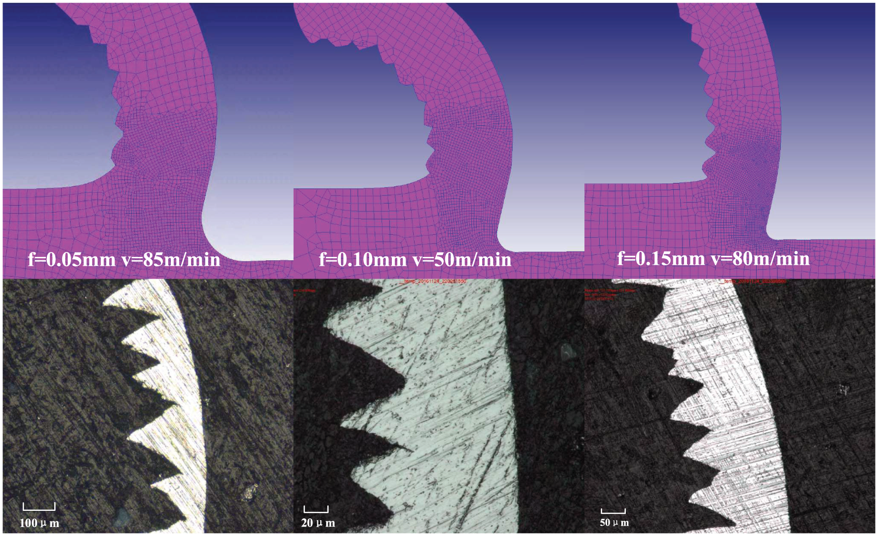
Experimental and predicted chip morphology.
To further demonstrate the superiority of the proposed constitutive model, simulations with the four different material constitutive models are compared with the experiments. Figure 12 shows the simulated and experimental average cutting force. It can be concluded that, compared with the other models, the proposed model tends to produce a higher accuracy on predicting cutting forces with the overall average error of 10.28%. And, the initial model has the largest prediction error of 37.03%. The prediction errors of Calamaz’s model and Sima’s model are 13.45% and 10.81%, respectively. Compared with the original JC model, the proposed JC material model has a large improvement of prediction accuracy on cutting force. However, it can be seen that the errors between simulation and experiment still exceed 10% using the proposed modified JC model. It may be due to the test error of chip thickness induced by the serrated shape. Another reason may be that the FEM does not consider the effect of insert coating on the performance. A noteworthy point is that the prediction accuracy of cutting force can further be improved using a more realistic friction model, such as pressure dependent shear friction model. 39
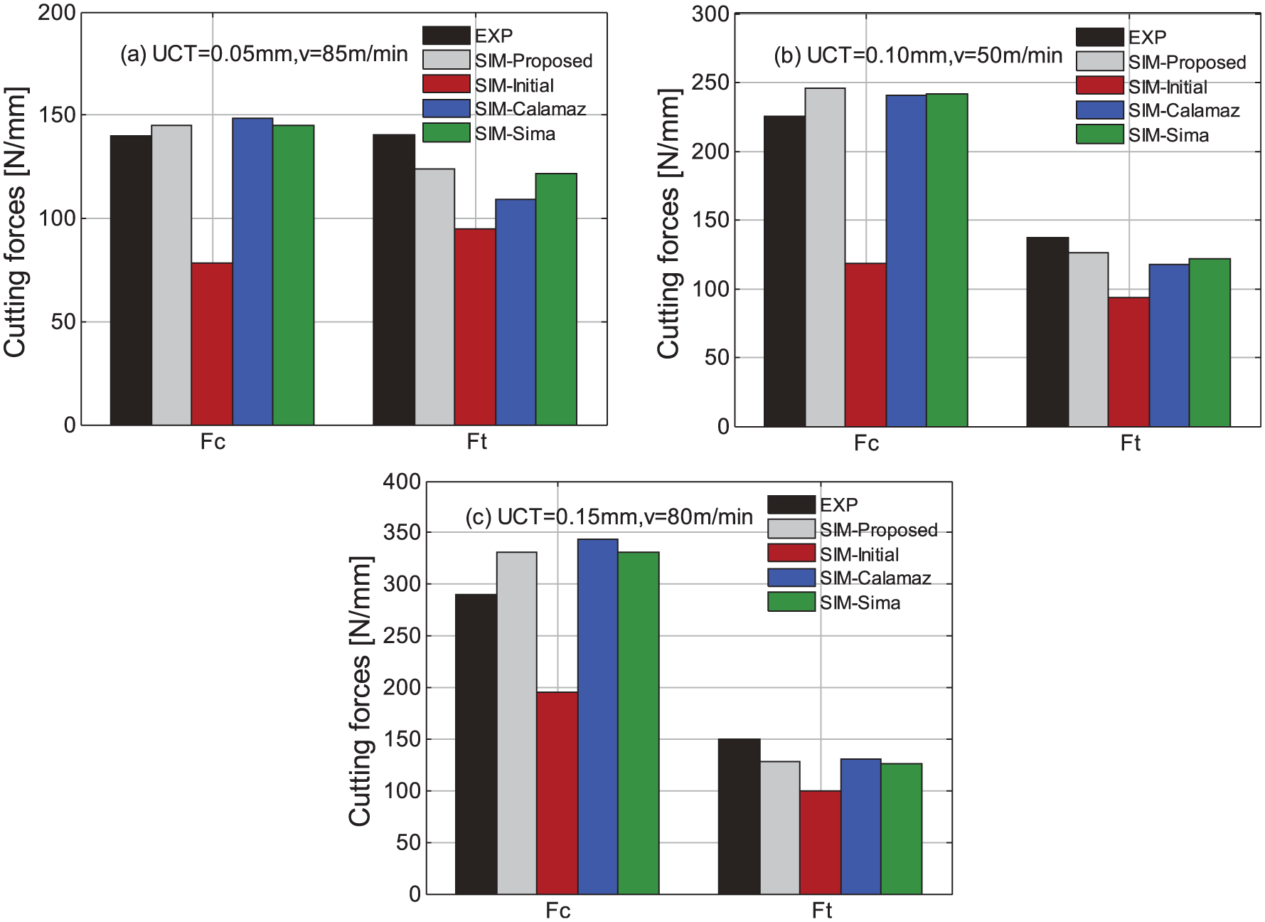
Measured and predicted average cutting force.
A lot of research works showed that cutting titanium alloy commonly produces serrated chip for a wide range of cutting speed.13,14,19–22 In this work, the serrated chip cross-section topography has also been observed, as shown in Figure 13. As mentioned above, serrated chip is the outward manifestation of the deformation localization induced by the thermal softening. It is also one of the characteristic features of the adiabatic shear in machining Ti6Al4V.
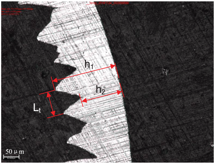
Measurement of serrated chip size.
The chip morphology is characterized by three parameters, including maximum chip thickness, minimum chip thickness, and sawtooth width. As shown in Figure 13, they are denoted as h1, h2, and Lt, respectively. Figure 14 displays the simulated and the measured chip size. It can be seen that the chip sizes predicted with the proposed model agree well with the measured results. In fact, the proposed model has the highest prediction accuracy. The total prediction errors with the proposed model, the initial model, Calamaz’s model, and Sima’s model are 18.12%, 59.53%, 57.50%, and 29.69%, respectively. The simulation errors of the maximum chip thickness, the minimum chip thickness, and the sawtooth width are 7.85%, 20.41%, and 26.09%, respectively. The relatively large prediction error on chip is due to the absence of fracture model in the finite element model of cutting Ti6Al4V titanium alloy. It needs to be pointed out that no serrated chips are found in all the simulations with Calamaz’s model. So, the sawtooth width simulated by the model equals to zero. As mentioned in section “Numerical model,” Calamaz’s research did not provide a complete optimal material parameters. 19 It is one of the reasons for producing the continuous chip for this model. However, the friction behavior is modeled according to Sima’s research, which is different from Calamaz’ study. 14 The different friction coefficient therefore has influence on the simulation results. Therefore, a further improvement on predicting chip size may be achieved by introducing realistic friction coefficient.
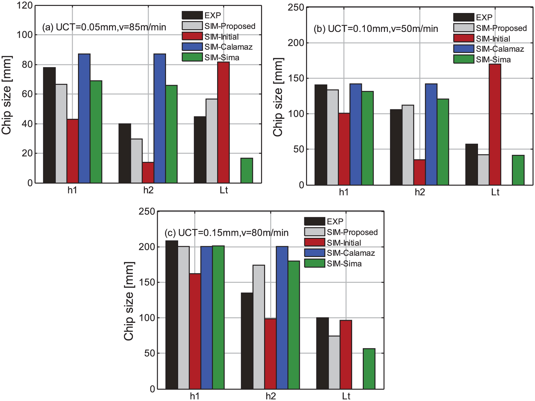
Measured and simulated chip size.
Conclusion
This article presents an inverse approach based on the UDPSSZ model for determining material constitutive law. The five additional parameters for the modified JC model of titanium alloy Ti6Al4V are accordingly identified using FA. The validation experiments show that the proposed inverse approach is effective to determine the modified JC constitutive model. Compared with other modified JC models from initial guesses and references, the developed material model tends to yield a larger improvement on predicting cutting force and chip size. Acceptable prediction accuracy with errors of 8.90% and 11.66% are achieved on the main cutting force and the feed force, respectively. Compared with cutting force, relatively large prediction error of 18.12% is obtained on chip size. But it could be improved by including a reliable fracture model in the finite element model of cutting Ti6Al4V titanium alloy. The serrated chip morphology is found, and cutting force presents cyclical fluctuation for all the simulations. It indicates that the flow stress softening leads to strain localization is captured in the finite element simulations. The simulation of cutting titanium alloy Ti6Al4V would benefit from further study on the friction behavior between cutter and workpiece. In addition, the developed inverse method can be extended to other metal material for machining.
Footnotes
Appendix 1
Author’s Note
Yong Jiang is now associated with Guangxi NanYe Machinery Equipment Co. Ltd, Nanning, China.
Declaration of conflicting interests
The author(s) declared no potential conflicts of interest with respect to the research, authorship, and/or publication of this article.
Funding
The author(s) disclosed receipt of the following financial support for the research, authorship, and/or publication of this article: This work was supported by the National Natural Science Foundation of China (No. 51775444) and the Fundamental Research Funds for the Central Universities (No.31020190502005).