
Abstract
Cathode design plays an important role in the electrochemical machining of aero engine blades and is a core issue influencing machining accuracy. Precision electrochemical machining of the leading edge of a twisted blade is particularly difficult. To improve the electrochemical machining accuracy of the leading edge, this article deals with cathode design by optimizing the design plane based on the three-dimensional potential distribution in the inter-electrode gap. A mathematical model is established according to the electrochemical machining shaping law, and the formation of the blade leading edge is simulated using ANSYS. The simulation results show that the blade leading-edge profile obtained with the optimized planar cathode is more consistent with the blade model profile. The optimized planar cathode and a non-optimized planar cathode are designed and a series of corresponding electrochemical machining experiments is carried out. The experiments show that the electrochemical machining process is stable and that the surface quality near the leading edge of the samples is slightly better than that of the body surface. Compared with the non-optimized planar cathode, the allowance difference at the leading-edge vertex is decreased by 0.062 mm. Using the optimized planar cathode allows fabrication of a workpiece whose shape is similar to that of the designed twisted blade.
Introduction
As core components of modern aeroengines, blades are generally made of hard-to-machine alloys such as titanium alloys or nickel-based superalloys. Furthermore, to obtain better aerodynamic performance, the blade shape is becoming ever more twisted and the manufacturing accuracy is increasing continuously.1,2 Therefore, blade machining presents a great challenge to the aerospace industry. Conventional processes, such as precision numerical control (NC) milling, precision forging and precision casting, can be used in the manufacture of turbine blades. For thin-walled, twisted blades, these traditional processes have reached their technological and economic limits, and an unconventional manufacturing technology such as electrochemical machining (ECM) could therefore offer a cost-effective alternative, with advantages that include high material removal rate, no tool wear, applicability to difficult-to-machine materials and absence of white layers or heat-affected zones.3–5
Because of the above advantages, ECM is applied widely to components with complex profiles, such as engine components. 6 In this type of non-contact machining, materials are removed by anodic dissolution and the workpiece profile is obtained by copying the cathode profile. Therefore, under certain electrical and electrolyte parameters, it is the tool cathode that determines the accuracy to which the workpiece is formed. To improve the machining accuracy, there has been a considerable amount of research into cathode design in the ECM process. Typical methods for cathode design include geometric design, the finite element (FE) method and the correction method. The cos θ method is a representative geometric design method employed by Tipton; 7 the assumption is that the inter-electrode gap (IEG) width is inversely proportional to cos θ, where θ is the angle between the normal to the workpiece boundary and the cathode feed direction.
The FE method has been developed with the extensive application of numerical calculation software. Jain and Pándey 8 described a way to use FE techniques to design a tool for ECM under specific conditions and predicted the shape of the anode for a tool with complex shape. Sun et al. 9 presented an FE method for designing tools for ECM, enabling the tool cathode to be designed from the profile data of a workpiece with a known three-dimensional (3D) freeform surface. Li and Niu 10 also presented an FE numerical method for cathode design based on the potential distribution in the ECM gap, and they analysed the convergence of the algorithm. McClennan et al. 11 described a numerical method for tool design for two-dimensional (2D) cases based on the electric field during the ECM process. Lu et al. 12 provided a numerical method for solving the design problems of 2D and 3D tools in steady-state ECM. Ernst et al. 13 proposed an inverse approach based on material-specific data to improve the adaptation of the cathode and shorten the development cycle, whereby the desired vane geometry was obtained. Yao et al. 14 carried out flow-field simulation for a thin, hollow cathode and proposed design rules for the cathode based on numerical fluid-dynamics analysis.
Starting with the initial tool design, the correction method has been a commonly used approach in cathode design. Reddy et al. 15 proposed an iterative-correction tool-design model based on using the correction method to correct the tool shape and the profiles were obtained by repeated amendments to meet the accuracy of the anode profile. Hardisty and Mileham 16 modified the cathode surface iteratively by converting deviations in the current density into position errors, thereby generating the desired tool shape iteratively with the specified workpiece shape. Zhu et al. 17 described a cathode design method based on iteratively correcting the predicted profile errors. First, based on the law of ECM forming, a mathematical model of machining forming was established. The prediction error was then simulated in ANSYS, whereupon the initial cathode profile was corrected iteratively according to the simulation results.
In addition, researchers have developed some novel cathode design methods for ECM. Alder et al. 18 proposed an analytical method for tool design based on Fourier series, which can be used for simulation by iterative techniques. Chang and Hourng 19 investigated how the thermal fluid properties of the ECM electrolyte influence the tool design; they used a 2D two-phase numerical model to predict the thermal fluid field. Kozak 20 developed a computer simulation system to address ECM manufacturing issues such as designing the tool electrode and selecting the machining parameters and optimization. Klocke et al. 21 developed an interdisciplinary simulation model for the ECM of aeroengine blades and showed that an appropriate cathode geometry could be calculated directly by inverse modelling. Purcara et al. 22 used the computer-aided design software SolidWorks integrated with an electromechanical 3D simulation system to design the electrode shape by analysing the electric field distribution in the gap region; they carried out a comparative study of a 3D forming simulation and a 2D cross-section simulation. Demirtas et al. 23 proposed a simplified mathematical model to obtain the cathode profile for ECM with a high-curvature freeform surface; their method requires only a few node coordinates of the anode surface and the boundary conditions to obtain the correct cathode surface. Liu et al. 24 presented a generic ECM anti-copy method with machining-gap control to eliminate the restriction on the anode material, and they revealed the machining-gap relationship between the anti-copy tool stage and the workpiece-copying stage. Shaikh et al. 25 conceived a novel twin-complementary-cathode design for electrochemical honing of gears and maintained a constant IEG between the workpiece and cathode gears.
It is difficult to manufacture the margin profiles of blades with precision ECM. Zhu et al. 26 proposed a cross-structural cathode structure for machining the leading/trailing edges of blades, which is designed only for 2D conditions. However, according to the basic principle of ECM, the influence of a 3D electric field on the blade edges during processing is evident in the case of a blade structure with a large twist. Therefore, it is unreasonable to design a cathode structure only in simplified 2D conditions. To achieve accurate ECM processing of the leading edge of a twisted blade, we design a pair of cathodes by optimizing the design plane based on the 3D potential distribution in the IEG of a twisted blade. Finally, we perform experiments and machine a sample with the optimized planar cathode.
Principle of optimizing the cathode design plane
ECM principle for a blade
The ECM process for a twisted blade is illustrated in Figure 1. As shown, the workpiece, the cathode and the electrolyte between them constitute an electrochemical reaction system. Electrolyte flows from the blade platform and is divided into two parts, which respectively flow across the convex and concave parts of the blade at high speed, taking with them electrolytic products and Joule heat. The concave and convex parts of the cathode, both connected to the negative power supply, feed towards the workpiece simultaneously in opposite directions; the blade, connected to the positive power supply, is held in a fixture. During the process, the blade is formed gradually from a blank to its designed shape.
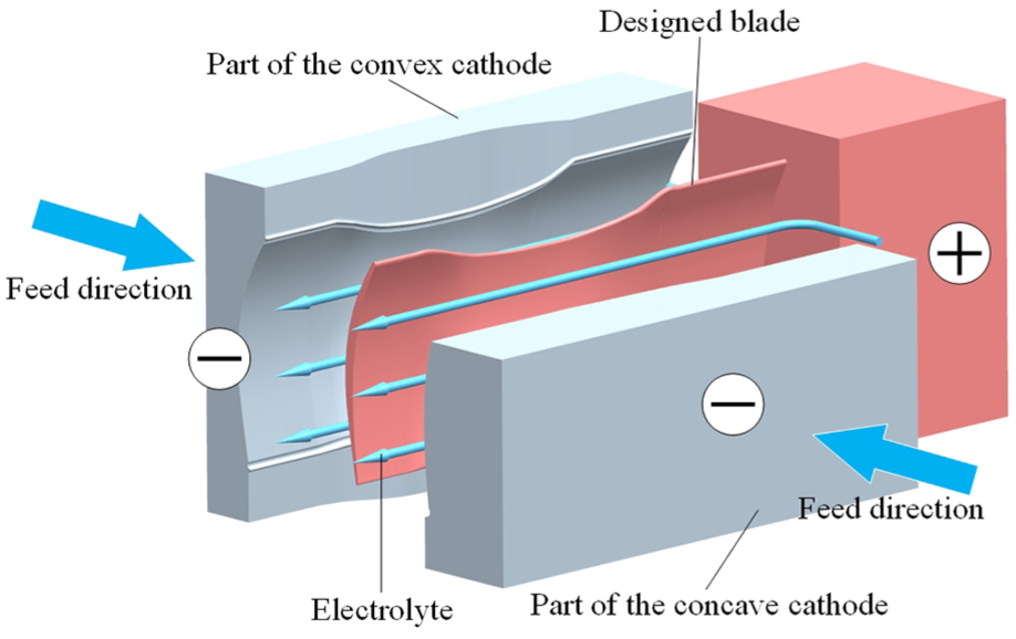
Schematic of electrochemical machining (ECM) process for twisted blade.
Traditional cathode design method
The full profile of the twisted blade designed herein is shown in Figure 2. The blade comprises a platform and a profile. The blade pedestal is used for installation in a fixture and plays electricity-conducting and positioning roles. The blade profile is divided into three parts, namely (1) the leading edge, (2) the body surface and (3) the trailing edge. The overall structure of the blade is clearly complex and distorted, especially near the blade root at the leading edge.
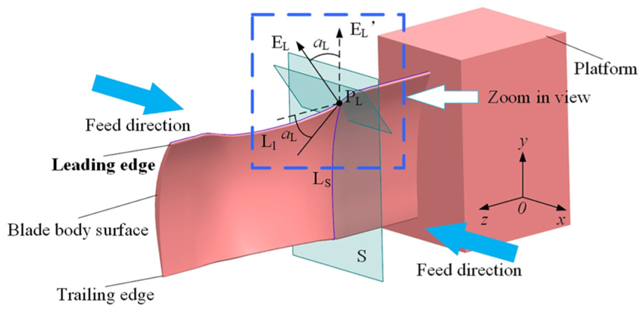
Full profile of designed twisted blade.
In traditional cathode design, the 3D blade model is sliced to transform it into a 2D planar problem. The cathode curve corresponding to each slice is then analysed independently, and finally all the cathode curves are combined into a continuous surface. An axial plane S (shown in Figure 2) is taken near the root of the leading edge of the twisted blade; plane S is parallel to the xoy plane and is used as the cathode design plane. Plane S intersects the blade model at the contour line LS. Point PL is the vertex of the leading edge on LS and is the point at which the y coordinate on LS is the largest. All the vertices on the blade leading edge are connected to form line Ll.
In the traditional 2D simplified method, as shown in Figure 3, because the design plane is 2D, the 3D normal electric field intensity in the IEG is replaced by the 2D electric field intensity. This causes errors in the design of the cathode profile and leads to considerable machining error of blades at their leading edges in the case of large twist angles. To address these shortcomings, a method for optimizing the cathode design plane based on the 3D electric field distribution in the IEG is proposed herein to improve the leading-edge precision of blades with large twist.
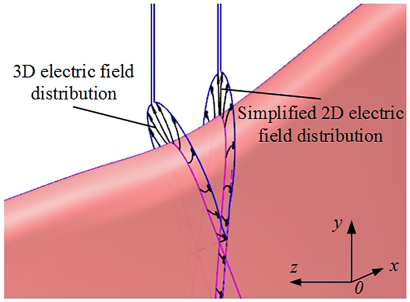
Three-dimensional (3D) electric field distribution in inter-electrode gap.
Method for optimizing the cathode design plane
According to the distribution of electric field intensity at the blade leading edge in the axial plane S in Figure 2, the optimized cathode design plane is shown in Figure 4. The actual electric field intensity EL in the ECM of the twisted blade at point PL is perpendicular to the tangent of Ll. Herein, we use the plane in which the actual electric field intensity at vertex PL is located as the cathode-optimization design plane. In the traditional 2D simplified method, the electric field intensity EL′ at the leading-edge vertex PL is perpendicular to the z axis. Therefore, the angle between the optimal design plane and the traditional design plane equals the angle between EL′ and EL. The latter angle can be obtained by measuring that between the tangent of the curve Ll at point PL and the z axis. Obviously, according to the law of cosines, the larger the value of αL, the smaller the component EL′ of the electric field intensity in the direction of the actual electric field EL and the larger the cathode design error, thereby increasing the profile error of the blade leading edge.
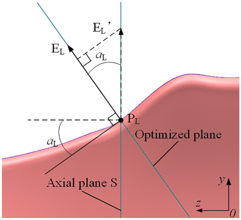
Schematic of electric field direction in ECM: magnified x-direction projection of leading edge.
Vertex PL as optimization parameter
Given the relatively small radius of curvature at the vertex of the leading edge, the electric field tends to concentrate there during ECM, resulting in relatively fast etching of the vertex and poor controllability of the vertex final processing position. If the position of vertex PL is too high or too low, an error will arise in the blade chord, thereby affecting the leading-edge contour accuracy. In Figure 5, an example is given in which the vertex PL′ of the actual machining profile of the leading edge is lower than vertex PL of the model profile. The errors between the model contour and the actual contour are D0, D1, …, DL, …, Dn-1, Dn from the convex side to the leading edge to the concave side, where DL is the leading-edge error at the vertex. The vertex error DL is often the maximum error in the leading-edge profile and has a greater effect on the accuracy of the leading edge than do the other points. Therefore, the position accuracy of vertex PL is a key parameter for ensuring the profile accuracy of the leading edge. Based on the above analysis, it is reasonable to use the plane corresponding to the direction of the electric field intensity at vertex PL of the blade leading edge as the optimized design plane.
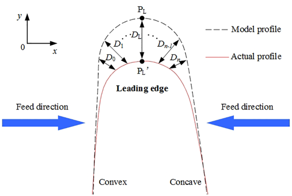
Schematic of processing error of blade leading edge.
In summary, the plane corresponding to the electric field intensity at vertex PL of the blade leading edge is defined herein as the cathode-optimization design plane. It can be obtained by rotating the axial plane S around a straight line passing through PL and parallel to the z axis.
Principle of optimal design of cathode profile
According to the above analysis, the cathode design accuracy can be improved by optimizing the design plane of the twisted-blade leading edge. Here, the difference in cathode geometry between the optimized planar cathode and a non-optimized planar cathode is compared quantitatively at first.
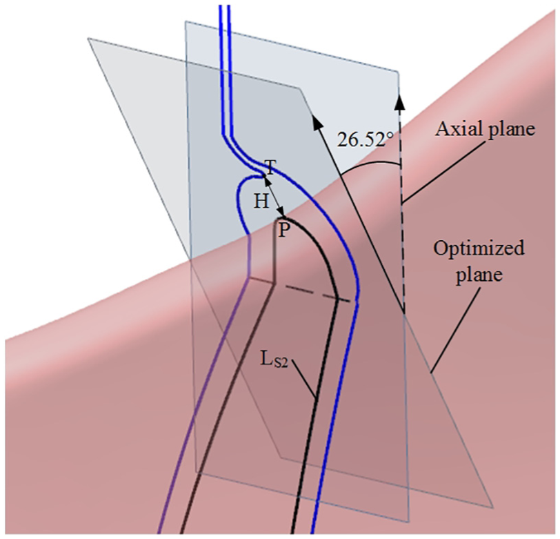
We use cross-structural cathodes at the leading edge (as shown in Figure 6), and this structure has the advantages of reducing the variation in machining current when forming the blade edge profile and improving the blade repeatability. 27 The distance H between the cathode crossed point T and the model-blade leading-edge vertex P is the key parameter of the cross-structural cathode design, where the blade tip P corresponds to vertex PL in Figure 4. The position of T is determined by the distance H and has a great influence on the position of the tip of the blade leading edge, thereby affecting the profile accuracy of the latter.
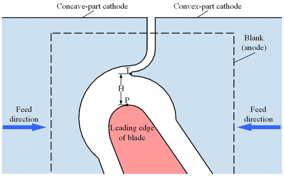
Sketch of cross-structural cathodes.
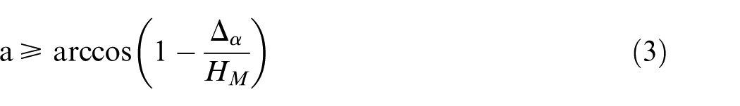
As shown in Figure 7, we analyse the improved cathode accuracy in the optimized plane of the blade leading edge. The blade observation angle is consistent with that shown in Figure 4. The region near point P is selected for analysis, where P is the arbitrarily selected leading-edge vertex. Here, the angle between the optimized plane and the axial plane S is a, the cathode crossed points are T1 and T2 and the corresponding vertex clearances are HP1 and HP2, respectively. The lines connecting the cathode crossed points in this region are approximately LT1 and LT2, and the distance between them is Δ α , which is the improved cathode design accuracy due to the optimized plane, namely

Because the cross-sectional profiles of the cathode in the optimized plane and the axial plane are the same, we have HP1 = HP2 = HM. Therefore, the improvement Δ α in the cathode design accuracy due to the optimized plane is

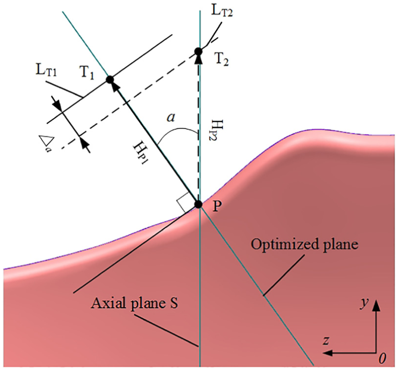
Diagram for analysing the increased precision of the cathode due to the optimizing design plane.
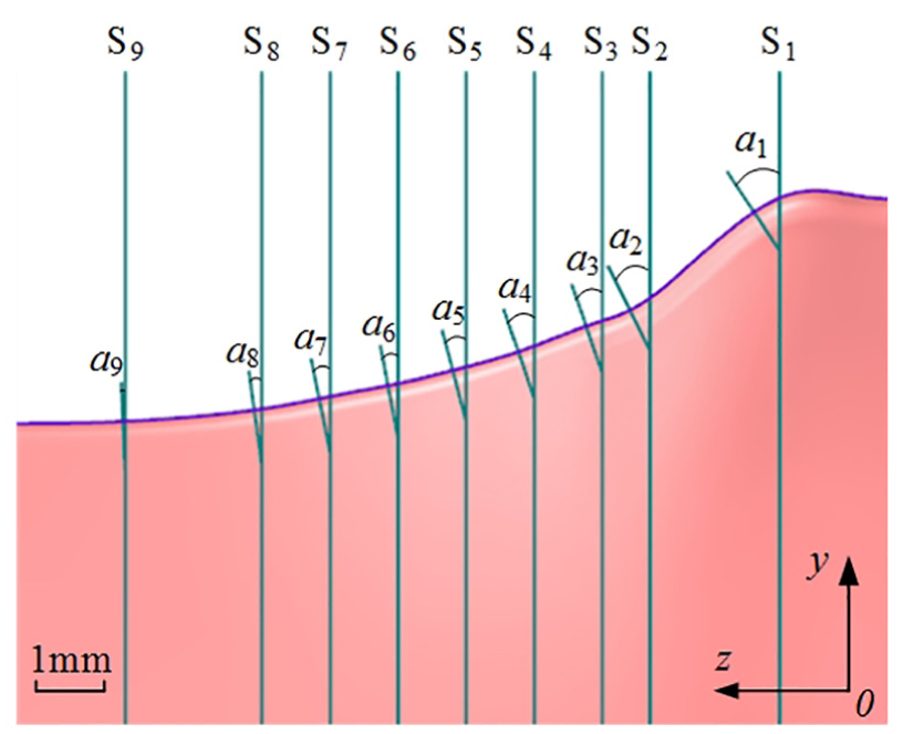
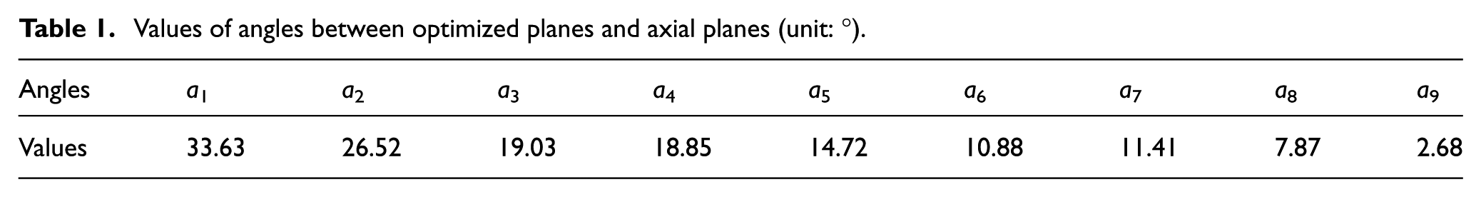
Herein, we take the twisted blade designed in Figure 2 as the research object. As shown in Figure 8, nine axial planes near the root of the leading edge of the twisted blade are selected for analysis, the angles between the axial planes S1–S9 and the corresponding optimized plane being a1–a9, respectively. The values of the angles between each axial plane and the optimized plane obtained by Unigraphics NX (UG) are given in Table 1.
Angles between optimized planes and axial planes.
Values of angles between optimized planes and axial planes (unit: °).
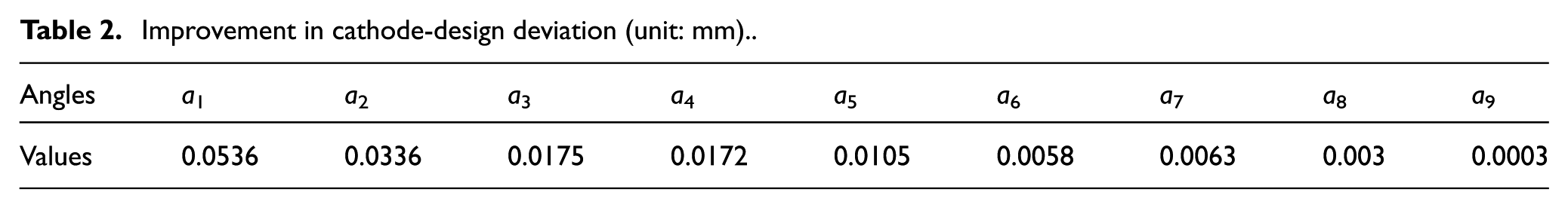
We calculate the incremental design deviation Δ α of the cathode contour line corresponding to each axial plane of the blade leading edge. The gap at the cathode crossed point of each axial plane is obtained through a simulation calculation. Zhu et al. 27 introduced a specific calculation method. The calculated value of H at each of these nine axial planes is 0.32 mm, meaning that HM = 0.32 mm. Therefore, according to equation (2), the design precision improvements of the cathode due to the optimized planes are shown in Table 2. At S1–S5, Δ α clearly exceeds 0.01 mm, whereas at S6–S9Δ α is less than 0.01 mm. Because it is difficult to guarantee the manufacturing accuracy of the cathode for Δ α less than 0.01 mm, we define the cathode design plane to be optimized when Δ α exceeds 0.01 mm. Therefore, for the twisted blade designed herein, as calculated by equation (3), when the angle between the optimized planes and the axial planes exceeds 14.36°, the cathode design plane must be optimized
Improvement in cathode-design deviation (unit: mm).
Herein, the axial plane S2 is selected for detailed analysis. As shown in Figure 9, the relevant cathode section profile is obtained by optimizing the design plane. The operation of other axial planes that require the design plane to be optimized is consistent with that of axial section S2.
Schematic of cathode design at twisted-blade leading edge.
Simulation of ECM process for blade leading edge
To verify the impact of the optimized planar cathode on the machining accuracy of the blade leading edge, we choose the cathode section profile at axial section S2 as a detailed research object. We conduct relevant forecasted profile simulations according to previous simulation of the blade ECM process. 17
Modelling and boundary-condition loading
The assumptions made about simplifying the blade leading-edge ECM model are as follows:
The electrical conductivities of both the cathode and anode are much larger than that of the electrolyte, and the electrodes can be treated as equipotential surfaces. 28
The current density depends on the conductivity of the medium in the gap and on the voltage according to Ohm’s law, and by introducing the total potential to account for the electrochemical reaction. 29
The machining rate at the anode satisfies Faraday’s law. 28
The electrolyte is homogeneous and has constant electrical conductivity. 30
A schematic of the electrical model close to the blade leading edge is shown in Figure 10. Boundary Γa is the suction side of the rectangular blank. Boundaries Γcc and Γcv are the convex-part and convex-part cathode profiles, respectively, both of which are fed towards the workpiece simultaneously. Boundary Γo is the fixture boundary; the fixture material is insulated and remains stationary. The workpiece, cathode and fixture boundaries together form a processing area that is filled with electrolyte. The specific conditions for the fixed boundary are


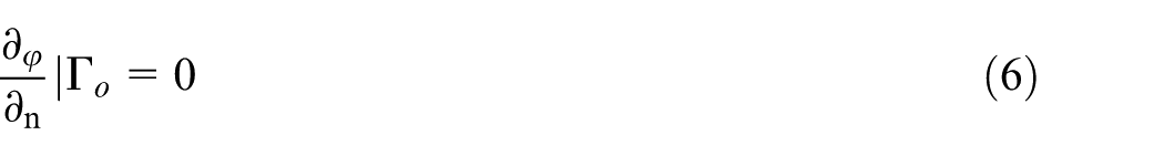
where

where n is the direction normal to the boundary.
Herein, the simulation parameters are as follows: U = 20 V; the frequency is 1000 Hz; the duty cycle is 55%; the electrolyte conductivity is 152 mS/cm, which is obtained from practical experimental measurements; the feed distances of the concave and convex parts of the cathode are determined by the crossed point T, and their feed rate is 0.5 mm/min. After setting all the boundary conditions and simulation parameters, the dynamic simulation is conducted using the ANSYS Parametric Design Language (APDL).
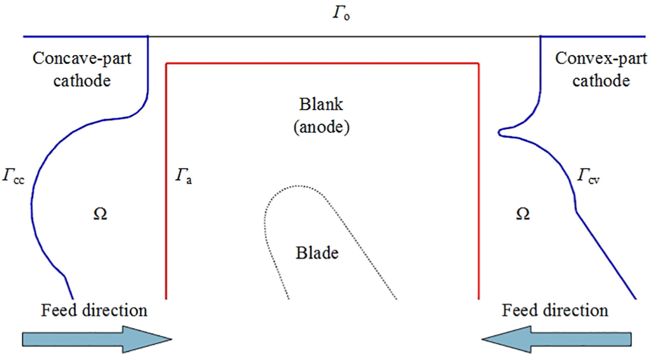
Schematic of electrical model close to blade leading edge.
Simulation principle of ECM process of blade leading edge
Based on Ohm’s law and Faraday’s law, the dissolution velocity of the workpiece contour is
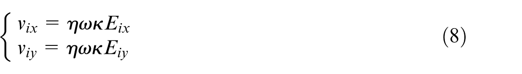
where vix and viy are the components of the dissolution velocity at the arbitrary ith point on the contour of the workpiece in the direction of the x and y coordinate axes, respectively, η is the current efficiency, ω is the volume electrochemical equivalent of the workpiece material, κ is the electrolyte conductivity and Eix and Eiy are the components of the electric field intensity at the ith point in the x and y coordinate directions, respectively.
For any point P(xi, yi) on the workpiece contour, after an iterative time Δt, its coordinates are updated once to P′(xi + 1, yi + 1). The formula for doing so is
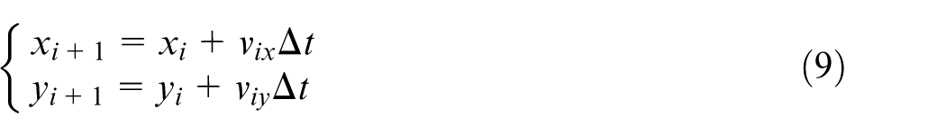
Using equation (9), the coordinates of a series of points on the leading edge of the workpiece can be simulated as the processing time changes. When the simulation process is conducted to the final moment, all the points on the contour of the leading edge of the workpiece are fitted to the spline curve in order, that is, the predicted workpiece.
Discussion of simulation results
Based on the analysis of the optimal design of the cathode profile in Figure 7, a simulation model of an optimized planar cathode and a non-optimized planar cathode is established using the corresponding cathode vertex gap H at axial plane S2. The two values of H used in the simulation are 0.32 and 0.286 mm, respectively.
The predicted blade leading-edge profiles are obtained as shown in Figure 11. For H = 0.32 mm, the predicted profile of the blade leading edge is basically the same as the model profile, and there is only a small amount of prediction bias. However, for H = 0.286 mm, the predicted blade profile has more material removed and its predicted contour exhibits obvious over-cutting. At this time, the predicted maximum profile deviation between H = 0.32 mm and H = 0.286 mm in the vertical direction is 0.051 mm, and the overall deviation of the blade leading edge by non-optimized planar cathode is large. Therefore, the accuracy of the cathode structure obtained by optimizing the design plane is higher.
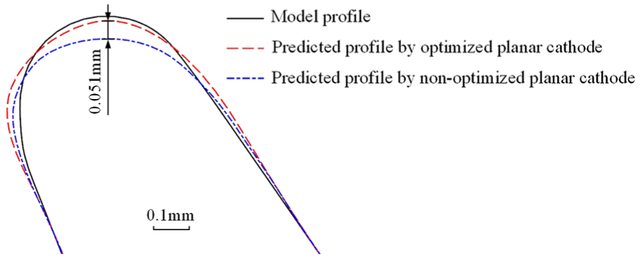
Predicted leading-edge profiles for both types of cathodes.
Experiments and discussion
Experimental conditions
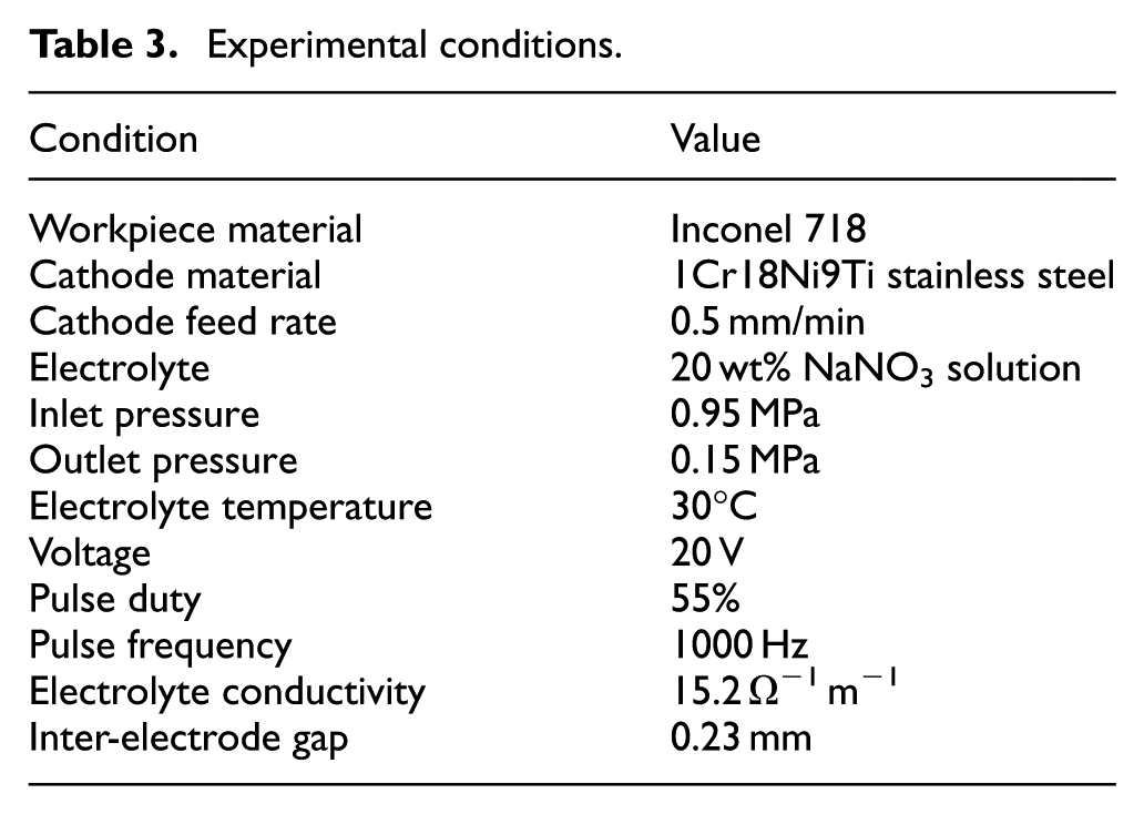
To verify the influence of the optimized planar cathode on the blade-forming effect, an ECM contrast experiment was conducted. The experimental conditions are listed in Table 3.
Experimental conditions.
The cathode model based on the optimized planar cathode design method is shown in Figure 12. Here, for comparative research, a set of cathodes that were not optimized for the plane were designed to be completed at the same time. Because of the particularly complex profile of the cathode, the two sets of cathodes were manufactured using a multi-axis milling machine. The designed twisted-blade ECM experiments were carried out using the two sets of cathodes according to the above experimental conditions.
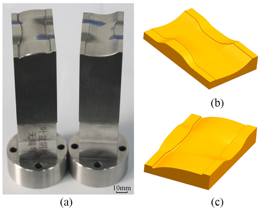
Optimized planar cathodes: (a) physical models, (b) convex part and (c) concave part.
A schematic of the fixture used for ECM of the blades is shown in Figure 13. During processing, the blade blanks are fixedly mounted in the fixture, while the convex and concave parts of the cathode feed uniformly at the same speed. The upper and lower fixtures are made specifically of insulating material to provide a sealed flow path for the electrolyte. The electrolyte flows from two inlets into separate convex and convex channels and finally converges at the tip of the blade. The cathodes and blanks are connected to the negative and positive poles, respectively, of the DC pulsed power supply.
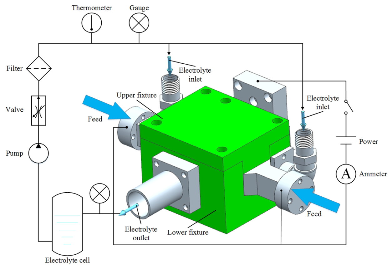
Diagram of blade machining fixture.
Experimental results and discussion
Current change during ECM
The current change during the ECM process for the twisted blade is shown in Figure 14. Obviously, the current change is stable throughout the process. The machining current varies with the cathode feed position and can be divided into three stages. In the initial stage, the cathode is fed from 0 to 7 mm, the blank machining area is formed gradually into a complex curved surface and the IEG is gradually uniform. In this stage, the machining current continues to increase steadily. The cathode is then fed from 7 to 9.8 mm, and the machining current is in a stable state because so are the machining area and the IEG. In the final stage from 9.8 to 11.4 mm, because of the gradual formation of the blade leading and trailing edges, the machining area is reduced rapidly, resulting in a rapid reduction of the machining current. According to the above analysis, the final position of the cathode is 11.4 mm and the constant cathode feed rate is 0.5 mm/min, as given in Table 3. Therefore, it takes 22.8 min to complete the machining of a single blade.
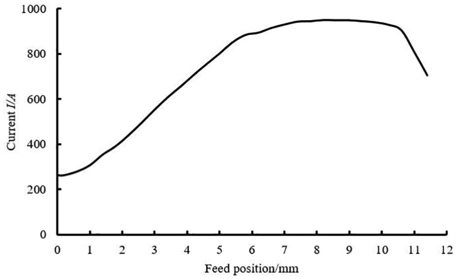
Machining current change during process with optimized planar cathode.
Machining profile accuracy
Figure 15 shows the blade machining samples. Sample (a) was obtained with the optimized planar cathodes and sample (b) was obtained with the non-optimized planar cathodes. Using a 3D coordinate measuring machine, the profiles of the leading edge were measured. The measurement results are shown in Figure 16. The results show that when using the optimized planar cathode, the profile of the blade leading edge is close to the theoretical profile. However, when using the non-optimized planar cathode, the material removal at the blade leading edge is increased appreciably and the overall contour is overcut. According to the measurement results, optimized planar cathodes can improve appreciably the machining accuracy of the twisted-blade leading edge. For the twisted blade designed herein, the precision of the leading-edge vertex at axial plane S2 has been improved by 0.062 mm. The experiment results are basically consistent with the simulation results. In addition, the maximum absolute values of the machining deviations at the leading edge for the optimized planar cathode and the non-optimized planar cathode blade are 0.039 and 0.067 mm, respectively. Therefore, using the optimized-design planar cathode, the machining accuracy of the blade leading edge was increased by 41.79%.
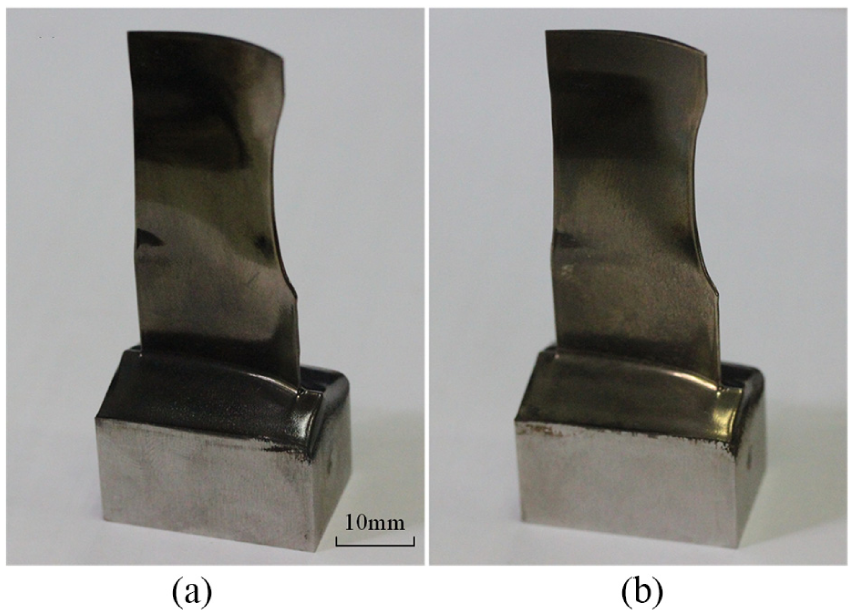
Machining samples using both types of cathodes: (a) optimized planar cathode; (b) non-optimized planar cathode.
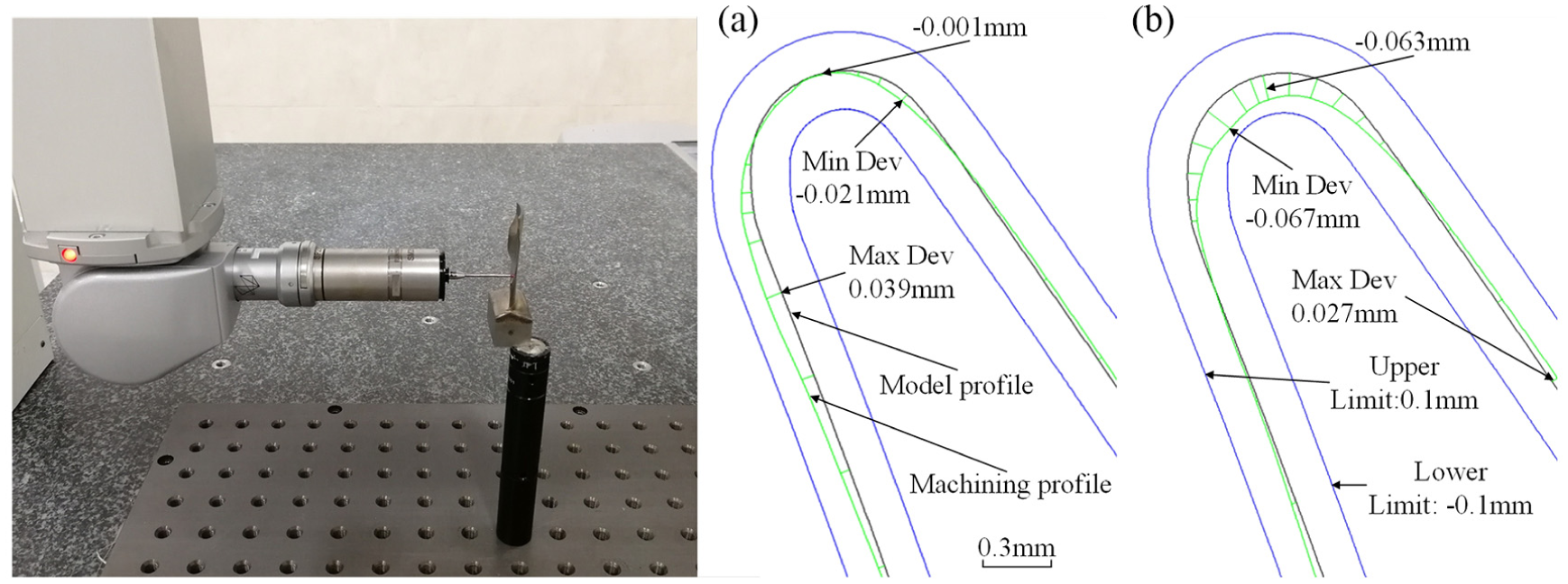
Samples of leading-edge profiles for both types of cathodes: (a) optimized planar cathode and (b) non-optimized planar cathode.
The profile simulations in this article are based on electric fields only, but blade ECM is a particularly complex process. The IEG is affected by factors such as pressure, temperature, electrolytic products and hydrogen evolution, in addition to being affected by the electric field. Therefore, there are some differences between the actual machining results and those of the theoretical simulation.
Analysis of surface morphology
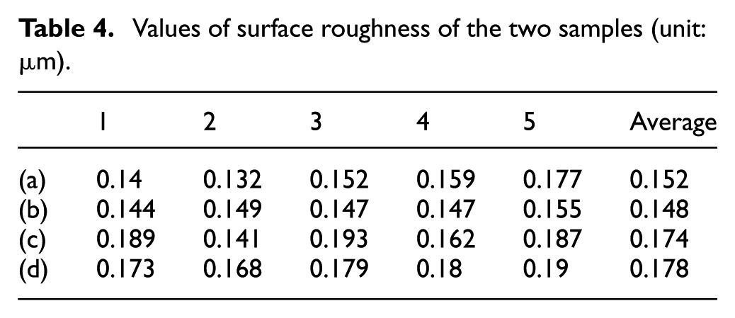
The 3D surface morphologies of both types of sample were detected with a 3D optical profiler (S-EOX; Sensofar, Spain) and the results are illustrated in Figure 17. Here, Figure 17(a) and (b) shows the surface topographies near the leading edges of the two samples, and Figure 17(c) and (d) shows the body surface topographies of the two samples. In these figures, the direction of electrolyte flow is along the y axis; evidently, there are no flow marks in any of the four locations. In addition, the surface roughness was analysed by taking five positions equally on the x axis on each of the topography charts; the results are given in Table 4. The surface roughness values near the leading edge of the two samples are basically the same, namely 0.152 and 0.148 μm, respectively. The surface roughness values of the body profile surface are also basically the same, namely 0.174 and 0.178 μm, respectively. Therefore, both samples have good surface quality. At the same time, we find that the surface quality near the leading edge of a sample is slightly better than that of the sample body surface. This is because the electric field intensity is concentrated near the leading edge of the blade and the machining current density is greater there than over the profile of the blade body, resulting in better surface quality.
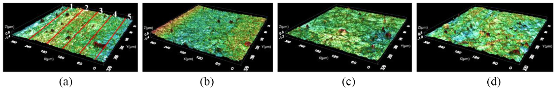
Samples of 3D surface morphology: (a) and (c) optimized planar cathode and (b) and (d) non-optimized planar cathode.
Values of surface roughness of the two samples (unit: μm).
Conclusion
An optimized planar cathode has been developed based on the 3D potential distribution in the IEG to improve the machining accuracy of the leading-edge profile of a twisted blade. The conclusions are as follows:
A method for optimizing the cathode design plane was proposed based on the distribution of the 3D electric field on the leading edge of the twisted blade, and this article defines the cathode design plane to be optimized when the improvement in the cathode design deviation exceeds 0.01 mm.
A 2D simulation model for optimized and non-optimized planar cathodes was established and a comparative simulation experiment was conducted. The simulations showed that the blade leading-edge profile obtained with the optimized planar cathode is more consistent with the blade model profile.
An optimized-planar-cathode ECM experiment was conducted. The experimental results showed that by optimizing the design plane of the leading edge of the cathode, the machining accuracy of the blade leading edge could be improved appreciably.
A reasonable cathode structure is very important for the ECM of blade leading edges. The method for optimizing the cathode design plane proposed herein can also be used to machine a workpiece with a shape similar to that of the designed twisted blade.
Footnotes
Appendix 1
Declaration of conflicting interests
The author(s) declared no potential conflicts of interest with respect to the research, authorship and/or publication of this article.
Funding
The author(s) disclosed receipt of the following financial support for the research, authorship and/or publication of this article: This study was sponsored by the National Natural Science Foundation of China (Grant no. 51675271), the Natural Science Foundation of Jiangsu Province (Grant no. BK20171413), the Fundamental Research Funds for the Central Universities (Grant no. NE 2017003) and the Qing Lan Project.