
Abstract
Stretch-flangeability of sheet metal is normally quantified by hole expansion ratio. Researchers have determined hole expansion ratio with various punch geometries such as conical, flat-bottom and hemispherical, and reported different hole expansion ratio values for identical test condition. Finite element investigation confirms that alteration of deformation path with punch geometries consequence different hole expansion ratio values. Necking and failure take place slightly away from the central hole edge for flat-bottom and hemispherical punches, while at the central hole edge for conical punch. Approximately plane strain tensile deformation prevails at the failure location for flat-bottom and hemispherical punches, while pure uniaxial tensile deformation prevails for conical punch.
Keywords
Introduction
Two failure criteria, forming limit curve (FLC) and hole expansion ratio (HER), are widely used to describe sheet metal formability of metals. Researchers determine the left side of the FLC from uniaxial tensile and notch tensile tests by local strain measurement on different sheet metals.1–6 However, determination of HER from normal uniaxial tensile test is not possible due to the fundamental difference of deformation process.7,8
HER is widely used as a limiting criterion during edge stretching operation of sheet metals. HER is normally measured from hole expansion test where a punch expands a central hole. Punch with different geometries such as conical, flat-bottom and hemispherical are used by various research groups. HER can be defined as
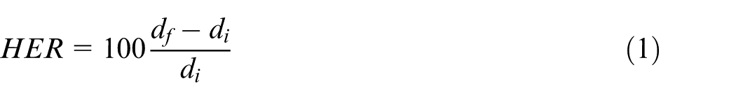
where
Experiment and finite element simulation
DP600 steel (an advanced high-strength steel (AHSS) which contains ferrite and martensite phases) with the initial sheet thickness of 1.85 mm is selected for this study. Tensile and HER with reamed edge experimental data are collected from the literature. 12 The schematic diagram of hole expansion test is illustrated in Figure 1(a). Geometries of conical, flat-bottom and hemispherical punches are shown in Figure 1(b). The conical punch has 50 mm diameter and 60° cone angle. Flat-bottom punch has 50 mm diameter and 9 mm profile radius. Hemispherical punch has 50 mm diameter and hemispherical profile with diameter of 50 mm as well. Punch, upper and lower dies are modeled as a rigid body. The punch movement is set at a constant velocity of 1 mm/s. Coefficients of Coulomb friction between tool and blank is set as 0.2. El-Magd’s 16 strain-hardening law is used to fit the true stress–strain curve of DP600 steel. El-Magd’s 16 strain-hardening law can be expressed as

where A, B and β are the material constants for El-Magd’s law. For DP600 steel, the values of
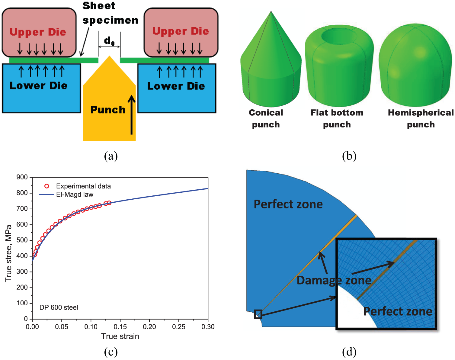
(a) Schematic diagram of hole expansion test; (b) different punch geometries for hole expansion test; (c) true tensile stress–strain curve and fitting of El-Magd’s law for DP600 steel (experimental data collected from Pathak et al. 12 ); and (d) one-quarter of sheet specimen for finite element simulation of hole expansion test.
Results and discussions
Figure 2(a)–(c) shows the in-plane maximum principal strain in hole expansion test sample for punch geometries of conical, flat-bottom and hemispherical, respectively. For conical punch, localized necking and failure are initiated at the central hole edge only (Figure 2(a)). However, localized necking and failure are initiated slightly away from the central hole edge (Figure 2(b) and (c)) for flat-bottom and hemispherical punches. Pathak et al. 12 and Suzuki et al. 18 have experimentally noted that crack is initiated slightly away from the central hole edge for hole expansion test with flat-bottom punch, while many researchers reported19–21 from experimental observation that crack is initiated at the central hole edge for hole expansion test with a conical punch. The cause of initiation of localized necking and failure at different locations for different punch geometries is discussed in Figure 3. Experimental forming limit data of DP 600 steel are collected from Pathak et al. 12 For conical punch, the strain paths at the edge of perfect zone and at the edge of damage zone (location of localized neck) are plotted in a diagram of major strain (ε1) versus minor strain (ε2). Both the strain paths follow perfectly uniaxial tensile deformation (Figure 3(b)). Deviation from uniaxial tensile strain path is found at the edge of damage zone after FLC, and it is because after initiation of localized neck, plane strain deformation prevails. For flat-bottom punch, the strain paths at the edge of perfect zone and at the failure initiation location (damage zone where localized necking occurs and crack initiates) are plotted in Figure 3(c). The strain path at the edge of the perfect zone is purely uniaxial tensile in nature, while the strain path at the failure initiation location (situated in the damage zone and little away from the central hole edge) is perfectly plane strain tensile deformation in nature from the beginning of the hole expansion test. For the hemispherical punch, the strain path at the edge of perfect zone is also purely uniaxial tensile in nature (Figure 3(d)), while at the failure initiation location (located in the damage zone and slightly away from the central hole edge) is complex in nature. Initially, deformation is uniaxial tensile up to 6% of major strain, after that deformation is almost equi-biaxial from 6% to 12% of major strain and after that almost plane strain tensile deformation path is followed until failure. This complex deformation path consequence intermediate HER result for hemispherical punch.
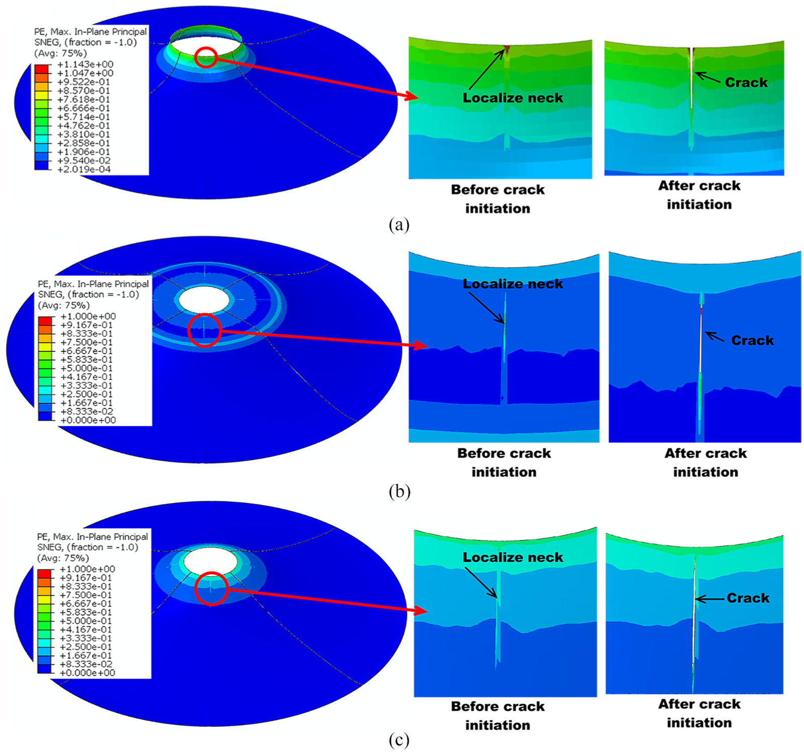
In-plane maximum principal strain in hole expansion test sample with different punch geometries: (a) conical punch with cone angle of 60°, (b) flat-bottom punch and (c) hemispherical punch.
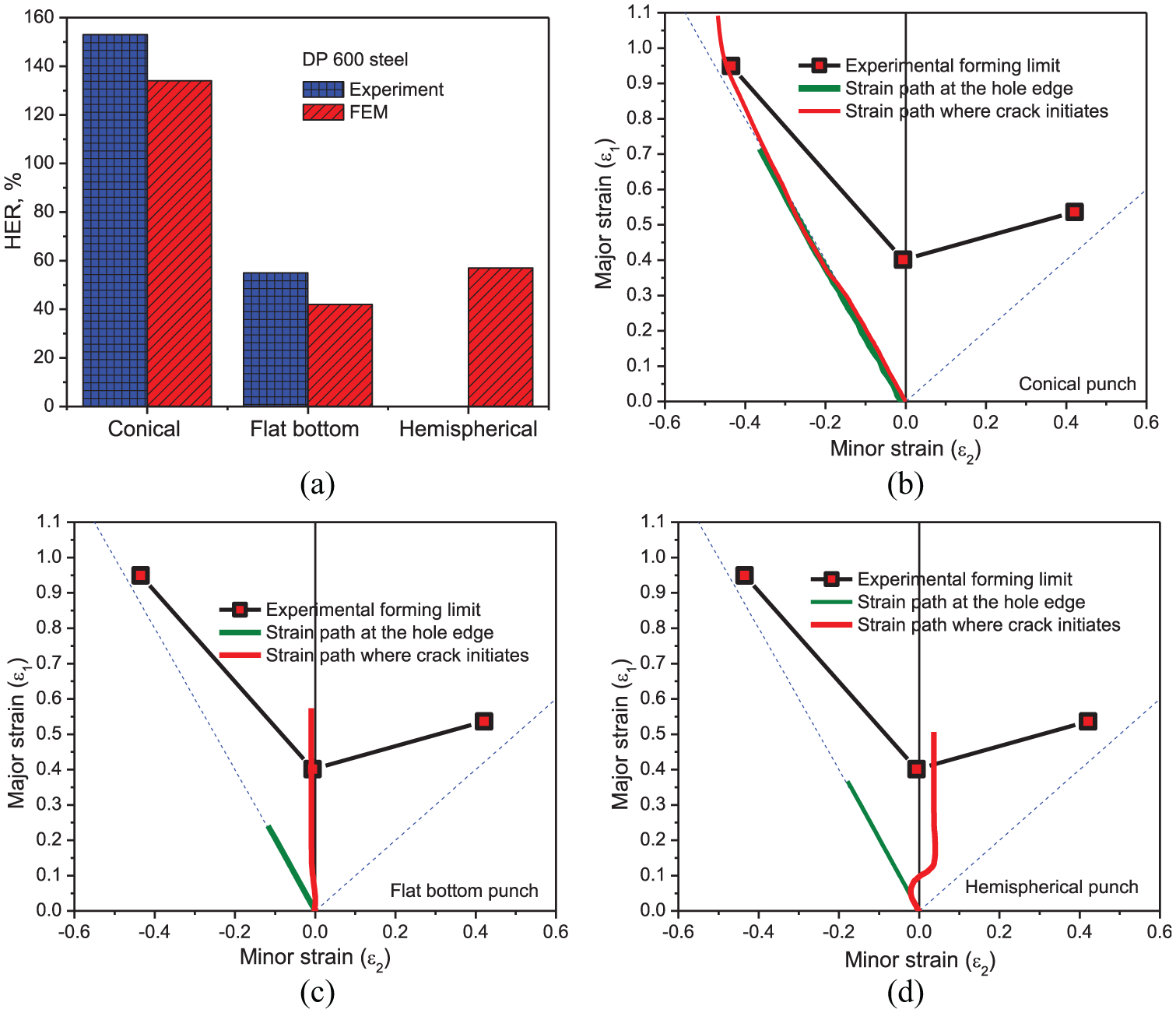
Experimental data collected from Pathak et al. 12 (a) Comparison of HER for different punch geometries; deformation paths during hole expansion test for different punch geometries. (b) Conical punch with cone angle of 60°, (c) flat-bottom punch and (d) hemispherical punch.
For detailed analysis, a line is selected on the sheet sample’s perfect zone as shown in Figure 4(a). In all the figures within Figure 4, the distance is taken from the central hole edge and distance increases as the point of interest moves away from the central hole edge. In-plane maximum (major strain, ε1), in-plane minimum (minor strain, ε2) and out-of-plane maximum (thickness strain, ε3) strains are plotted with distance in Figure 4(b)–(d) for conical, flat-bottom and hemispherical punches, respectively. From Figure 4(b)–(d), it can be stated that irrespective of punch geometries, the deformation state on the central hole edge is uniaxial tensile. However away from the central hole edge, the deformation state alters with punch geometries. Very little deviation from uniaxial tensile deformation state is observed for conical punch. However, plane strain followed by biaxial tensile deformation states are observed for both flat-bottom and hemispherical punches. From the diagram of major strain (ε1) versus minor strain (ε2), that is, forming limit diagram (Figure 3), it can be noted that localized necking takes place earlier for plane strain condition and late for uniaxial tensile deformation. Therefore, little away from the central hole edge (Figure 2) as plane strain deformation condition exists, localized necking and failure initiation will be logically commencing at that location. Pathak et al. 12 and Suzuki et al. 18 have experimentally observed similar finding for hole expansion test with a flat-bottom punch. Detailed finite element analysis also perfectly explains the mechanism behind it.
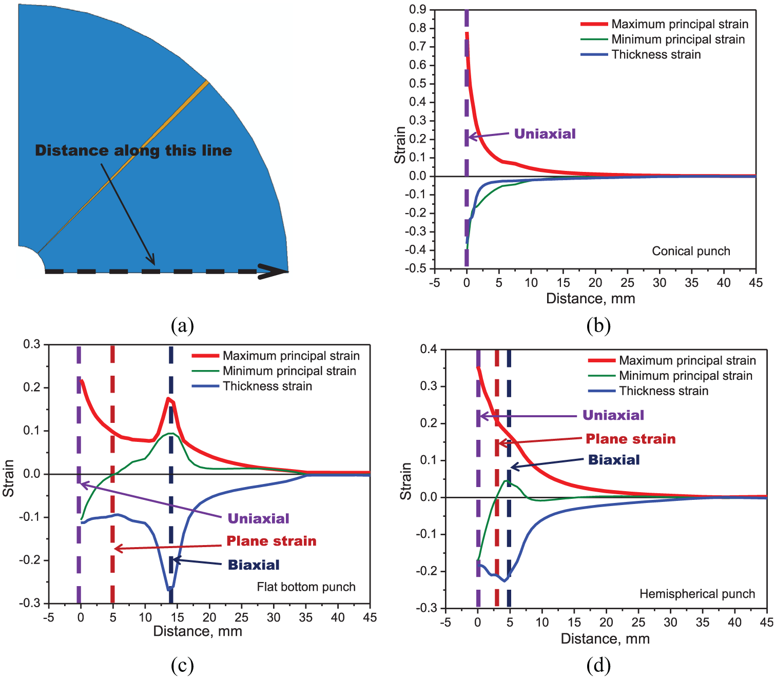
(a) Schematic diagram of distance (i.e. distance moving away from the central hole edge); variation of in-plane maximum, in-plane minimum, out-of-plane maximum (thickness) and principal strains along the width of the sample (i.e. distance specified) for different punch geometries. (b) Conical punch with cone angle of 60°, (c) flat-bottom punch and (d) hemispherical punch.
As necking and failure do not take place at the central hole edge for flat-bottom and hemispherical punches, edge conditions have little effect on the HER. Pathak et al. 12 also reported from the experimental result that central hole edge condition has little effect on the HER with flat-bottom punch. Localized necking followed by failure occurs little away from the central hole edge where plane strain tensile deformation state prevails. Therefore, the failure during hole expansion test with flat-bottom and hemispherical punches is due to plane strain localized necking which is exactly the same as in the forming experiment (Nakajima test). As a result, the true stretch-flangeability of sheet metal can be quantified from the hole expansion test with conical punch only.
Conclusion
In this study, a detailed finite element analysis has been done to simulate hole expansion test with different punch geometries such as conical, flat-bottom and hemispherical. To capture instability numerically, MK model is introduced in the sheet specimen. Finite element simulation result states that localized necking and failure take place from the central hole edge for hole expansion test with conical punch, while necking and failure occur slightly away from the central hole edge for hole expansion test with flat-bottom and hemispherical punches. Deformation state at the failure location for conical punch is uniaxial tensile, for flat-bottom punch is perfectly plane strain tensile and for hemispherical punch is complex and roughly plane strain tensile (i.e. uniaxial tensile followed by biaxial, and finally plane strain). Stretch-flangeability of sheet metal can be measured from hole expansion test with the conical punch, while hole expansion test with flat-bottom and hemispherical punches replicates failure condition of plane strain necking.
Footnotes
Acknowledgements
The author expresses his gratitude to Dr S. Tarafder, Head, Division of Materials Engineering, CSIR-National Metallurgical Laboratory (Jamshedpur, India), and Dr Saurabh Kundu, Chief Product Research, R&D, Tata Steel Limited (Jamshedpur, India), for their valuable suggestions.
Declaration of conflicting interests
The author(s) declared no potential conflicts of interest with respect to the research, authorship and/or publication of this article.
Funding
The author(s) received no financial support for the research, authorship and/or publication of this article.