
Abstract
Stretch-flangeability of sheet metal is normally represented by hole expansion ratio. Hole expansion ratio cannot be determined from uniaxial tensile test though uniaxial tensile deformation occurs at the hole’s edge, because of fundamental difference in deformation and damage processes present between hole expansion test and uniaxial tensile test. It is proposed that only localized necking is observed in hole expansion test; however, diffuse necking followed by localized necking is observed in uniaxial tensile test of sheet metal. It is noticed that the hole expansion ratio is marginally higher than maximum diffuse neck strain determined from uniaxial tensile test with local strain measurement by digital image correlation technique. The absence of diffuse neck in hole expansion test with defect-free central hole (i.e. electrical discharge machined hole) results far higher hole expansion ratio than uniform elongation of the material.
Keywords
Introduction
Sheet metal formability is normally controlled by primarily two forming properties: forming limit curve (FLC) and hole expansion ratio (HER). Definitely, the low HER of advanced high-strength steel is the primary bottleneck to reduce the weight of automotive structures.1–4 Researchers established direct correlation between left side of the FLC and tensile properties of various sheet metals.5–11 The left side of FLC can be determined directly from normal tensile and notch tensile tests,12–15 as similar deformation and necking are observed. However, HER cannot be determined directly from the uniaxial tensile test though uniaxial tensile deformation prevails at the hole’s edge during hole expansion test. One of the prime reasons is the hole edge condition.16–19 Central hole of the hole expansion test sample is normally prepared by punching process. Researchers reported the presence of micro-cracks and dimples at the shear edge of the central hole.16–19 For the same reason, researchers recently established correlation between HER and fracture toughness.17,18,20,21
Many researchers reported the correlations between the tensile properties and HER of specific steel groups,22–31 but the relationships are not universal and not derived from the fundamental of deformation process. Researchers also reported the relationship between the micro-structural features of material and the HER,3,30,31 but limited to similar steel grades. Therefore, in order to clearly understand the governing factors of stretch-flangeability, the differences in deformation and damage behavior between hole expansion test and uniaxial tensile test should also be taken into consideration. In this investigation, the fundamental of deformation and damage aspects of stretch-flangeability, of sheet metals, are experimentally studied.
Experimentation
Cold-rolled ferritic steel (high-strength interstitial free steel) and dual-phase (DP) steel (contains ferrite and martensite phases) are selected for this investigation. Sheet thickness of ferritic and DP steels are 0.7 and 1.4 mm, respectively. Flat tensile specimens with a gauge length of 25 mm are used. A constant strain rate of 0.001 s−1 is maintained throughout the uniaxial tensile test. All tensile experiments are carried out in laboratory environment in a 100 kN loading capacity servohydraulic test frame. All tests are continued until fracture of the tensile sample. Basic tensile properties of selected steels are tabulated in Table 1. Commercially available two-dimensional (2D) digital image correlation (DIC) system from LaVision 32 is used for local strain measurement. Normally, 100–200 images per test specimen are stored for determination of local strain components.
Mechanical properties of ferritic and dual-phase steels.
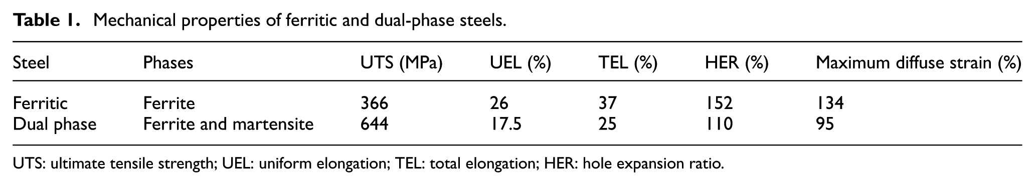
UTS: ultimate tensile strength; UEL: uniform elongation; TEL: total elongation; HER: hole expansion ratio.
Hole expansion test is carried out on a 100×100 mm2 square-shaped sheet specimen with a center hole diameter of 10 mm, using a conical punch with cone angle of 60°. Center hole of the hole expansion test sample is prepared by electrical discharge machining (EDM).
Results and discussion
Deformed specimen after hole expansion test is shown in Figure 1(a). The presence of multiple localized neck and visible crack at the central hole edge after hole expansion test is observed. Figure 1(b) shows the schematic diagrams of deformation process in uniaxial tensile test and hole expansion test. Uniform deformation takes place during uniaxial tensile test, while a clear deformation gradient present for hole expansion test specimen (edge of the central hole to edge where blank holds by die/punch). Highest tensile deformation is noticed at the hole edge and the amount of deformation decreases with increasing distance from the central hole edge. Figure 2 shows the schematic details of deformation and necking in uniaxial tensile test and hole expansion test. Normally, necking of sheet metal during uniaxial tensile test can be classified into two categories such as diffuse and localized necking. Normally, localized necking is observed after diffuse necking in sheet metal. Strain concentrations in both the width and thickness directions are comparable in case of diffuse necking. In contrast, the strain concentration in the thickness direction is far higher than that in the width direction for localized necking (i.e. an indication of plane strain deformation). Necking can only takes place at the central hole edge for hole expansion test. Continuous presence of material (edge of central hole to edge where blank holds by die/punch) and existence of deformation gradient (high deformation at central hole edge and negligible deformation at blank holding portion), consequence suppression of diffuse neck formation at the central hole edge. Only localized neck formation is observed at the central hole edge during hole expansion test with EDM cut central hole (almost defect free at central hole edge).
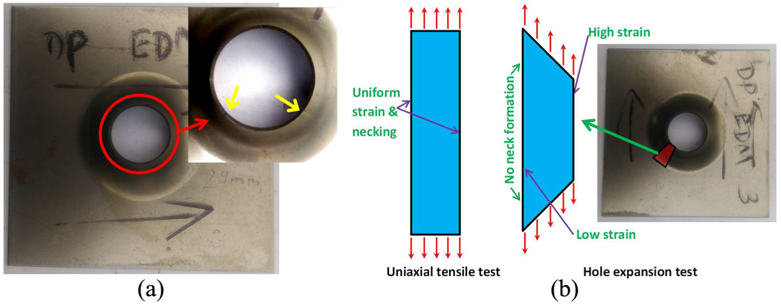
(a) Specimen after hole expansion test: localized neck and visible crack and (b) deformation gradient in hole expansion test and uniform deformation in uniaxial tensile test.
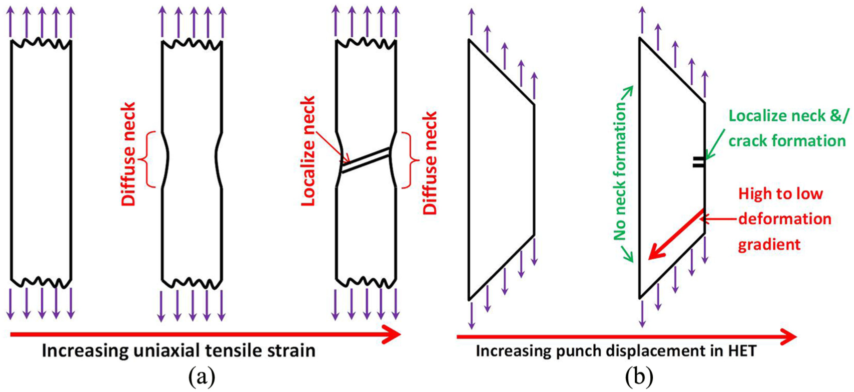
Details of deformation and necking in (a) uniaxial tensile test: diffuse neck followed by localized neck and (b) hole expansion test: no diffuse neck, only localized neck and crack propagation.
In normal uniaxial tensile test, the overall engineering strain is measured by contact extensometer. However, the strain at necked region cannot be measured by contact extensometer. DIC technique can be effectively used to measure axial strain at the necked region. 33 DIC technique is adopted in this work to measure local strain at necked region.
Two different zones one at the necked region and other at the outside of necked region but within the gauge length are selected for further examination. The evolution of local strain components (εXX and εYY ) at the two selected zones at various overall strain levels are plotted in Figure 3(a) and (b). At outside the necked zone, local strain components (both εXX and εYY ) remain almost constant after uniform elongation. Whereas at the necked zone, local strain components (both εXX and εYY ) increase rapidly with increase in overall strain level after uniform elongation. Figure 3(b) shows a region where both strain components (εXX and εYY ) increase with straining after uniform elongation, and in this region, diffuse necking takes place. After that, εXX in necked zone remains constant, while εYY increases with straining, and in this region, localized necking occurs. This indicates that during localized necking, the axial elongation takes place at the expense of thinning (thickness strain), while width remains constant implying a plane strain deformation condition. However, the localized neck is not distinguishable with DIC for DP steel in Figure 3(b). From Figure 3, maximum diffuse true strain (strain at which localized neck initiates) for DP and ferritic steels are observed as 0.67 and 0.85, respectively. Corresponding maximum engineering diffuse strain of DP and ferritic steels are 95% and 134%, respectively (obtained from simple true to engineering strain conversion formula).
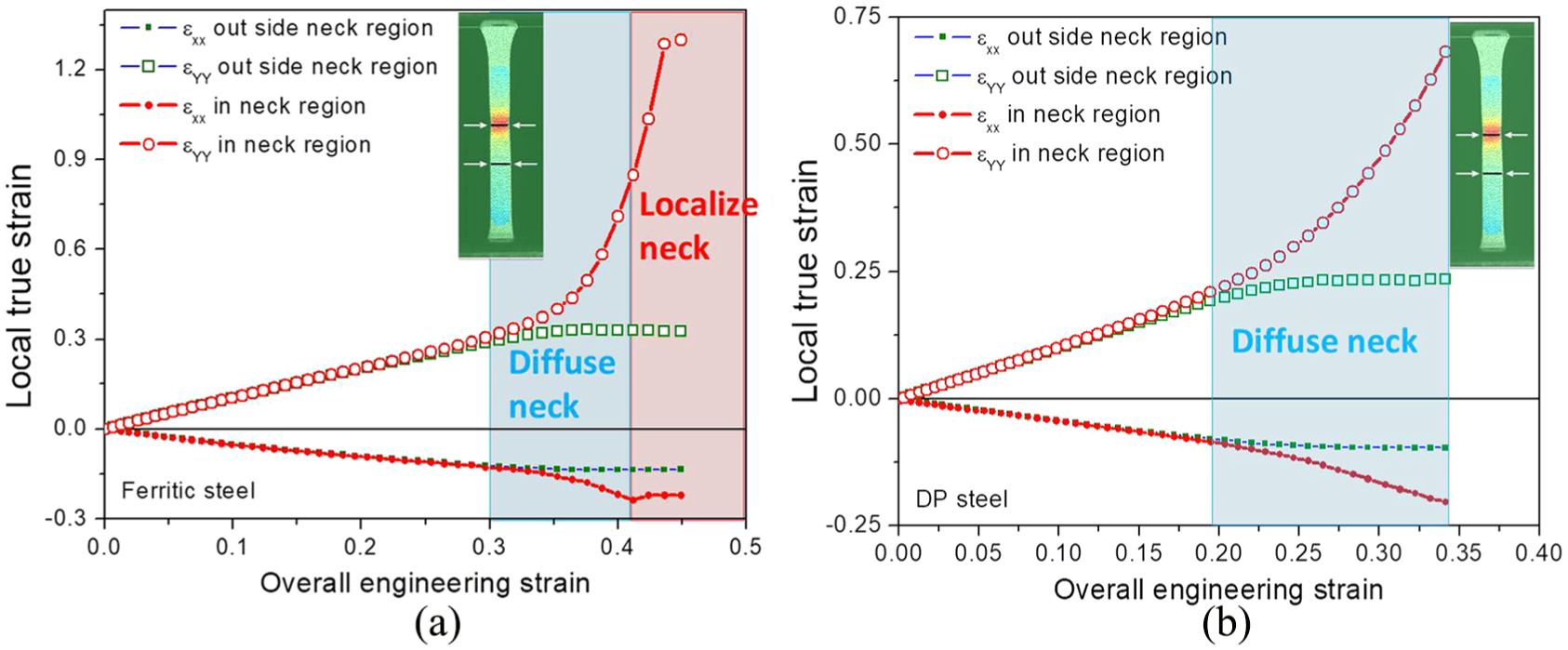
Evolution of local average strain components (εXX and εYY ) at various overall strain levels during a tensile test of(a) ferritic steel and (b) DP steel.
Negligible number of defects are present at the central hole edge which is machined by EDMtechnique.16–19,21,25 HER for DP and ferritic steel sheets are 110% and 152% for EDM-machined hole, respectively (Figure 4). The uniform elongation of DP and ferritic steel sheets are 17.5% and 26%, respectively. The total elongation of DP and ferritic steel sheets are 25% and 37%, respectively. Hole expansion test is generally stopped after visible through-thickness crack formation. Therefore, localized necking and crack propagation also have contribution in HER. This conclusion is valid for the hole edge without defect condition (e.g. EDM-machined hole).
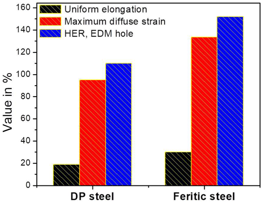
Comparison of hole expansion ratio (HER) for DP and ferritic steels.
Conclusion
For the first time, author showed that the absence of diffuse necking during hole expansion test results higher HER for EDM-machined central hole (i.e. defect-free central hole edge) than total elongation obtained from uniaxial tensile test. Maximum diffuse neck strain (i.e. strain at which localized neck initiates) is determined for both DP and ferritic steel sheets from uniaxial tensile test with local strain measurement by DIC technique. For both the steels, maximum diffuse neck strain is very much closer and little lesser than HER of EDM-machined hole, that is, defect-free hole edge. Contribution from localized necking and crack propagation (micro-crack to through-thickness visible crack) are responsible for this little deviation.
Footnotes
Acknowledgements
The author expresses his gratitude to Dr S. Tarafder, Head, Division of Materials Engineering, CSIR-National Metallurgical Laboratory, Jamshedpur 831007, India and Dr Saurabh Kundu, Chief Product Research, R&D, Tata Steel Limited, Jamshedpur 831001, India for their valuable suggestions.
Declaration of conflicting interests
The author(s) declared no potential conflicts of interest with respect to the research, authorship, and/or publication of this article.
Funding
The author(s) received no financial support for the research, authorship, and/or publication of this article.