
Abstract
In this study, experiments of high-speed face milling of A6061 aluminum alloy with a carbide insert milling cutter under dry cutting conditions were conducted. The contact length between tool and chip, the workpiece vibration amplitude, and the arithmetic average surface roughness were measured under varying cutting conditions (cutting speed, feed rate, and depth of cut). The characteristics of chip morphology were observed using scanning electron microscope. Experimental results showed that the increasing cutting speed reduced the tool–chip contact length, the workpiece vibration, and the surface roughness. The tool–chip contact length, the workpiece vibration, and the surface roughness were all increased with increasing cutting depth and feed rate. The results of chip morphology showed that the chips with serrated form were generated under high-speed cutting conditions. Moreover, scratch lines, plastic deformation cavities, and local molten chip material were observed on the slide chip surface.
Keywords
Introduction
Aluminum alloys have been widely used in the aerospace and automotive industries due to their low density, high specific strength, and specific stiffness.1,2 They are also employed in many engineering structures because of the increasing demands for lightweight structures. As a result, there is an increased need for machining of aluminum alloys. In addition, research on the optimization of cutting conditions for aluminum alloy machining has attracted significant attention from researchers.3–5 Among the modern manufacturing technologies, high-speed machining (HSM) is an innovative technique, which can improve machined surface finish, enable machining of difficult-to-cut materials, and offer high productivity.6,7 In metal cutting, the cutting speed, feed rate, and depth of cut are three main controlling parameters. The information on chip morphology, tool–chip contact length, and workpiece vibration is crucial for insight observation of tool life, cutting stability, and other machining properties. 8 Specifically, chip morphology contains deep information about the cutting mechanisms and machinability of an alloy in a cutting process. The tool and chip contact length closely concerns the area of interaction between the hot chip and the tool surface, and therefore the interface heat transfer zone. 9 The vibration of the workpiece significantly influences the surface integrity, especially when milling thin-walled components.10,11 Among the surface integrity aspects, surface roughness is one of the basic criteria for assessing the quality of a machining process. 12
Many experimental studies have been performed to explore the influence of cutting parameters on performance characteristics of HSM with aluminum alloys. The cutting forces, chip segmentation, and built-up-edge (BUE) formation in dry machining of the ductile aluminum alloy AA2024-T351 were studied.13–15 It was reported that the degree of chip segmentation was highly influenced by tool rake angle and uncut chip thickness. The contact/friction change at the tool–work material interface was the main reason of BUE formulation, which would be promoted by the ductile properties of the aluminum alloy. Ye et al.16,17 highlighted the evidence of serrated chip formation during the HSM of several high-strength aluminum alloys. Huang et al. 18 proposed a regression equation, which reflected the relationship between the cutting parameters and the residual stresses during high-speed end milling of the 7050-T7451 aluminum alloy. Pham et al. 19 also proposed equations for cutting force and chip shrinkage coefficient in milling of the A6061 aluminum alloy. Kazban et al. 20 measured cutting forces and temperature distribution at the tool tip in high-speed orthogonal machining of 6061-T6 aluminum alloy using a modified Hopkinson bar apparatus. Recently, ultra-high-speed machining (UHSM) is being investigated. Zhong et al. 21 investigated the surface morphology and microcrack formation of the 7050-T7451 aluminum alloy with slot milling speed up to 5000 m/min. The critical cutting speed and ductile-to-brittle transition mechanism for the workpiece material in UHSM of 8000 m/min were studied by Wang et al. 22 They found that the quality of surface finish with UHSM is worse than that of HSM due to the remained brittle fracture and fragment adhesion. Therefore, UHSM was recommended for rough machining or semi-finishing.
Besides the experimental approach, with the continuous development of numerical methods, the finite element method (FEM) has become an effective tool for the simulation of HSM of aluminum alloys. A numerical investigation on the serrated chip formation during HSM of the AA7075-T651 aluminum alloy was carried out by Jomaa et al. 23 They showed that the chip segmentation would occur in the adiabatic shear banding process at high cutting speeds. Shear strain localization at the tool tip and its propagation partway to the free surface of the work material were found to be the main causes of serrated chips. Ye et al. 16 carried out finite element simulations to obtain the dimensionless critical cutting speed at which the serrated chip flow is generated in HSM of several aluminum alloys. Xu et al. 24 introduced a theoretical calculation model of chip parameters applicable for high-speed orthogonal cutting of the aluminum alloy 6061-T6. Based on a finite element model, Pham et al. 25 studied the optimized cutting conditions for high-speed milling of the A6061 aluminum alloy considering objectives of cutting force and chip shrinkage coefficient. Several other numerical models for dry orthogonal cutting simulations of the A2024-T351 aluminum alloy have also been proposed.4,26,27 One model created by Madaj and Píška 26 adopted the smoothed particle hydrodynamics (SPH) method. This model was capable of predicting cutting forces and continuous chip morphology. Another model, called arbitrary Lagrangian–Eulerian (ALE) model, was also proposed.4,27 It was shown that the ALE approach is an appropriate formulation to study the adhesive layer formation along the tool rake face and chip formation process in HSM with transient cutting conditions.
The pioneer works have contributed great significance to understanding the physics and mechanics of aluminum alloys during HSM. However, there have been few studies on high-speed face milling of the A6061 aluminum alloy with an insert carbide cutter. Although this is one of the most common alloys of aluminum for aerospace, automotive, and general-purpose uses,28–30 some high-speed cutting characteristics have not been discussed sufficiently. In this work, high-speed face milling of the A6061 aluminum alloy is carried out with varying cutting parameters, that is, cutting speed, feed rate, and cutting depth. Based on the experimental results, the effects of cutting parameters on tool–chip contact length, workpiece vibration, and roughness of surface finish are examined. Properties of the generated chip morphology are analyzed using scanning electron microscope (SEM) images.
Experimental setup
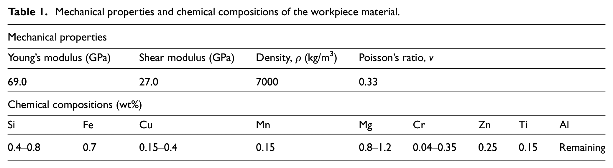
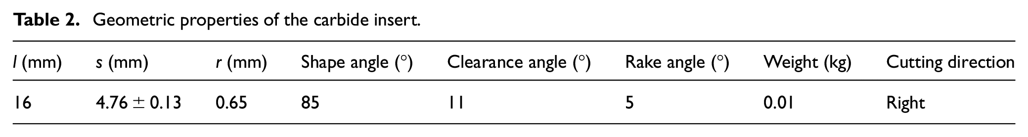
The experiments are conducted on an HS Super MC500 computer numerical control (CNC) vertical milling center. The workpiece is an A6061 aluminum alloy rectangle having the dimensions of 70 mm length, 80 mm width, and 30 mm thickness. Table 1 shows the mechanical and chemical compositions of the workpiece material. Dry cutting tests are performed by a 40-mm-diameter cutting tool and the radial depth of cut of 30 mm. Ceramic carbide inserts coated PVD TiN with ISO designation of APMT 1604 PDTR and grade LT 30 are mounted in the body of the cutter. The geometric and physical properties and chemical composition of the insert carbide are specified in Tables 2 and 3, respectively.
Mechanical properties and chemical compositions of the workpiece material.
Geometric properties of the carbide insert.
Physical properties and chemical composition of the carbide insert.
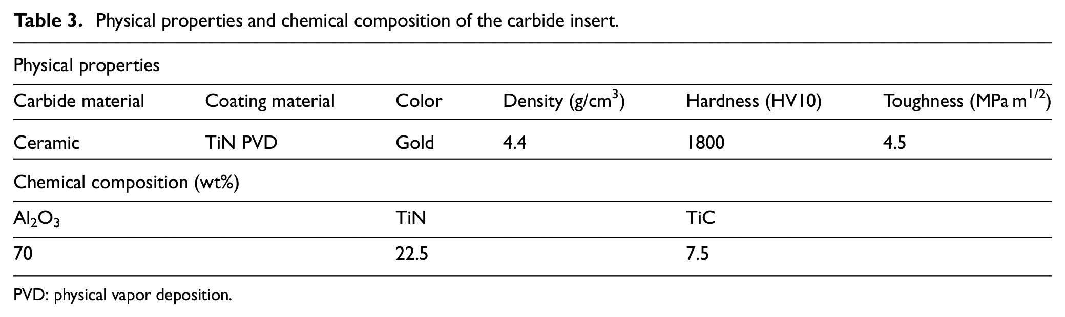
PVD: physical vapor deposition.
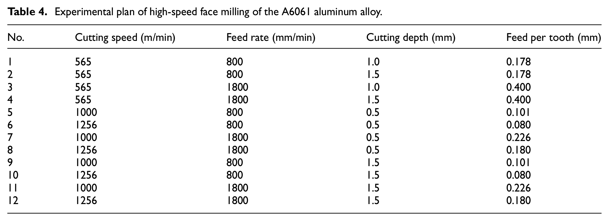
The vibration of the workpiece during cutting is measured by a three-axis acceleration sensor Triaxial DeltaTron® accelerometer of type 4525-B-001 (Brüel & Kjær). Silicone glue is used for mounting the accelerometer directly on the workpiece clamping fixture as shown in Figure 1. The accelerometer is able to measure vibration in three mutually perpendicular directions. The accelerometer is connected to a data acquisition (DAQ) device LAN-XI type 3160-B-042 (Brüel & Kjær). The measured signal is finally transferred to a laptop computer and then processed by a fast Fourier transform analysis. The sampling rate of vibration measurement is 131 kHz, and a low pass filter with a cutoff frequency of 10 kHz is applied on the measured signal. In order to measure vibration, two-step measurements are conducted. First, the measurement of a workpiece with an idle spindle, that is, without tool and workpiece interaction, is performed. Then, the workpiece vibration is measured while the tool is performing the cutting process. Subsequently, the final vibration is obtained by subtracting the vibration of the first step from that of the second step. This will help minimize the influence of environmental disturbances on the final vibration data. The contact lengths between the tool and the chip are assessed using a Keyence digital microscope model VHX-2000E. A SEM model S-4800 (Hitachi) is used to observe the generated chip morphology. The surface roughness of the workpiece is measured by a Mitutoyo surface roughness tester model SJ-400, which has a stylus tip radius of 5 µm, a resolution of 0.125 nm, and a stylus angle of 60°. All the surface roughness measurements are performed based on a 0.8 mm cut-off length and a 2.4 mm evaluation length. For the purpose of the investigation, the milling speed of 565–1256 m/min, the table feed rate of 800–1800 m/min, and the cutting depth of 0.5–1.5 mm are selected in the experiments. The feed per tooth can be determined accordingly from the cutting speed, table feed rate, tool diameter, and number of insert carbides. As a result, feed per tooth values ranging from 0.08 to 0.4 mm are calculated. The overall experimental plan is presented in Table 4. Each experimental test is repeated at least three times to ensure repeatability.
Experimental plan of high-speed face milling of the A6061 aluminum alloy.
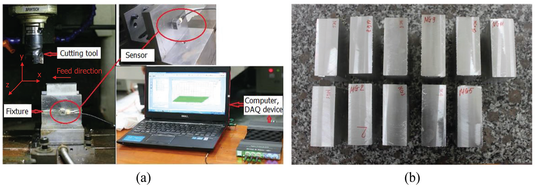
Experimental setup of high-speed milling: (a) experimental setup of cutting test and workpiece vibration measurement and (b) machined workpieces.
Experimental results
This section presents the experimental results of the chip morphology, tool–chip contact length, workpiece vibration, and machined surface roughness.
Chip morphology
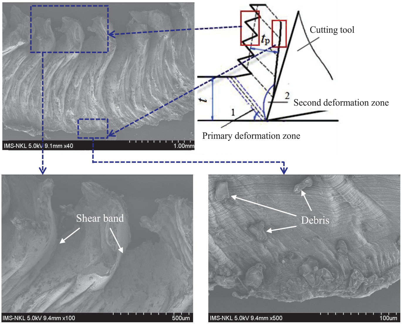
Observation of chip morphology during high-speed milling of the A6061 aluminum alloy is presented. Because there is no significant difference in chip morphology under a high cutting speed, only one sample of chip morphology is analyzed here with cutting speed V = 1256 m/min, feed rate f = 1800 m/min, and depth of cut t = 1.5 mm. Figure 2 shows typical SEM morphology of the chips, which take a main serrated form over their thickness. It is observed that the chip experienced monotonic changes in the degree of serration over its entire thickness. At a high cutting speed, under the effect of high strain and temperature, distinct shear slip occurs in the primary deformation zone, which is a slight trapezoidal deformation matrix as shown in Figure 2. As a result, serrated chips are generated mainly due to the thermal softening phenomenon and adiabatic shear occurred in a narrow zone. Figure 2 also shows the magnified side view of the chip surfaces. The slide surface, which is the surface contacting with the rake face of tool where the chip flows, is quite smooth. It is shown that there is a clear evidence of plastic deformation that occurred at the slide surface. This is because significant heat is generated in the secondary deformation zone resulting from sliding friction at the tool–chip interface zone. Metal debris is also observed nearby the slide surface of the chip. The free surface is rough where the adiabatic shear bands occur.
Chip morphology obtained in high-speed milling of the A6061 aluminum alloy.
Figure 3(a) illustrates the detailed plan view of the slide surface of the chip. Figure 3(a) clearly shows the sliding region with visible scratch lines, which are produced due to the friction of the flowing chip over the tool’s rake face. Figure 3(a) additionally shows the cavities, which are caused by sticking of the chip material to the tool, subsequently by its fracture beneath the slide surface of the chip. Moreover, local melting occurs on slide surface, which results in molten chip deposited on the slide surface (Figure 3(a)). This is caused by the effect of high temperature rise during cutting. Figure 3(b) shows the plan view of free surface of the chip. A rough surface mostly with minute wrinkles and metal debris can be observed from Figure 3(b). Moreover, the wrinkles are not perpendicular to the cutting direction, which could be attributed to the non-uniform deformation of the chip after cutting.

Slide and free surfaces of the chip generated in high-speed milling: (a) slide surface and (b) free surface.
Tool–chip contact length
The contact length between the tool and the chip is determined by measuring the length of the contact track on the insert rake face after the cutting tests. Therefore, tool–chip contact length reflects the length of the frictional interface between chip formation and rake face generated along the secondary deformation zone.
Figure 4 displays the digital image of the rake surface, from which the tool–chip contact length can be identified. Figure 4(a) illustrates the tool–chip contact length measured under the milling conditions of cutting speed V = 1256 m/min, feed rate f = 1800 m/min, and depth of cut t = 1.5 mm. Figure 4(a) also shows the adhesion of the workpiece materials on the cutter edge. During high-speed cutting, chips flowed out along the rake face, but there were still some small chips adhering on the cutter. Figure 4(b) shows the tool–chip contact length measured at a lower feed rate of f = 800 m/min, while the cutting speed and cutting depth are the same as in Figure 4(a). Reducing the feed rate obviously reduces the contact length between the tool and the chip because lowering the feed rate leads to the reduction of uncut chip thickness. Figure 4(c) shows the tool–chip contact length with a lower cutting depth of t = 1 mm. The other cutting conditions are V = 1128 m/min and f = 1300 mm/min. Compared to Figure 4(a) and (b), it can clearly be seen from Figure 4(c) that a reduction in cutting depth reduces the distribution length of chip trace on the tool rake face as indicated by a distance H. Moreover, the tool–chip contact length also changes, which further proves a strong dependence of the tool–chip contact length on the process parameters.
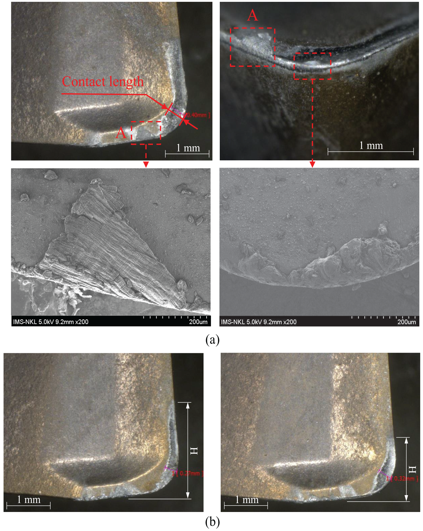
Measurement of tool–chip contact length: (a) V = 1256 m/min, f = 1800 m/min, t = 1.5 mm; (b) V = 1256 m/min, f = 800 mm/min, t = 1.5 mm; and (c) V = 1128 m/min, f = 1300 mm/min, t = 1.0 mm.
Detailed tool–chip contact length with varying cutting parameters is shown in Figure 5. With the cutting speed ranging from 565 to 1256 m/min, the tool–chip contact length varies within the range of 0.27–1.03 mm. The tool–chip contact length increased with the increase of feed rate or cutting depth. On the contrary, the tool–chip contact length decreases with the increasing cutting speed, which indicates a reduction in shear deformation during HSM.
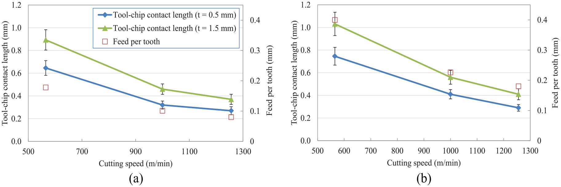
Measured tool–chip contact length with varying cutting parameters: (a) f = 800 (mm/min) and (b) f = 1800 (mm/min).
Vibration of the workpiece
Vibrations in milling are mainly caused by the exciting forces generated by the cutting teeth as they enter and leave the workpiece. In addition, the variation in chip width during milling also leads to self-exciting vibrations. One of the most critical vibration problems in milling is chatter vibration. Chatter is a kind of self-excited vibrations, which occur during the generation of chip thickness in the cutting operations.31–33
To determine the chatter and non-chatter vibration frequencies analytically, the mechanical model of the milling process can be constructed. Accordingly, based on Newton’s law, the mass of the tool, the damping coefficient, and the spring stiffness are used to elaborate into the equations of motion. Then, by applying several mathematical transformations, frequencies during chatter can be determined as follows 34


where fH and fPD refer to the secondary Hopf bifurcation and the period doubling bifurcation, respectively, which show up during chatter. Ω is the rotational speed of the tool in r/min, and z is the number of cutting teeth. ω is equal to ln(µ)/τ, where τ = 60/(zΩ), and µ indicates a characteristic multiplier of linear time-periodic delay-differential equations of motion. In the case of stable milling, non-chatter vibration frequencies can be calculated by

where fTPE reflects the tooth pass excitation effect.
As mentioned in section “Experimental setup,” two-step measurements are carried out to measure vibration of the workpiece. Figure 6(a) shows the frequency spectrum of vibration measured in the first step with an idle spindle. This figure clearly shows multiple harmonics of fn, which is the natural frequency of the workpiece and the clamping fixture system. Figure 6(b) displays the frequency spectrum of vibration measured in the second step with the tool and the workpiece interaction. Multiple harmonics of the natural frequency fn and also the tooth passing frequency of the cutting tool fTPE are observed in Figure 6(b). The final vibration results obtained by subtracting the vibrations in Figure 6(a) from those in Figure 6(b) are demonstrated in Figure 6(c). As shown in Figure 6(c), the cutting point is in a stable domain because only multiple tooth pass frequencies (i.e. non-chatter vibration frequencies) are observed in the vibration spectrum. 34 Therefore, vibrations during this high-speed milling are mainly caused by the exciting forces caused by the insert cutter when it enters and leaves the workpiece.
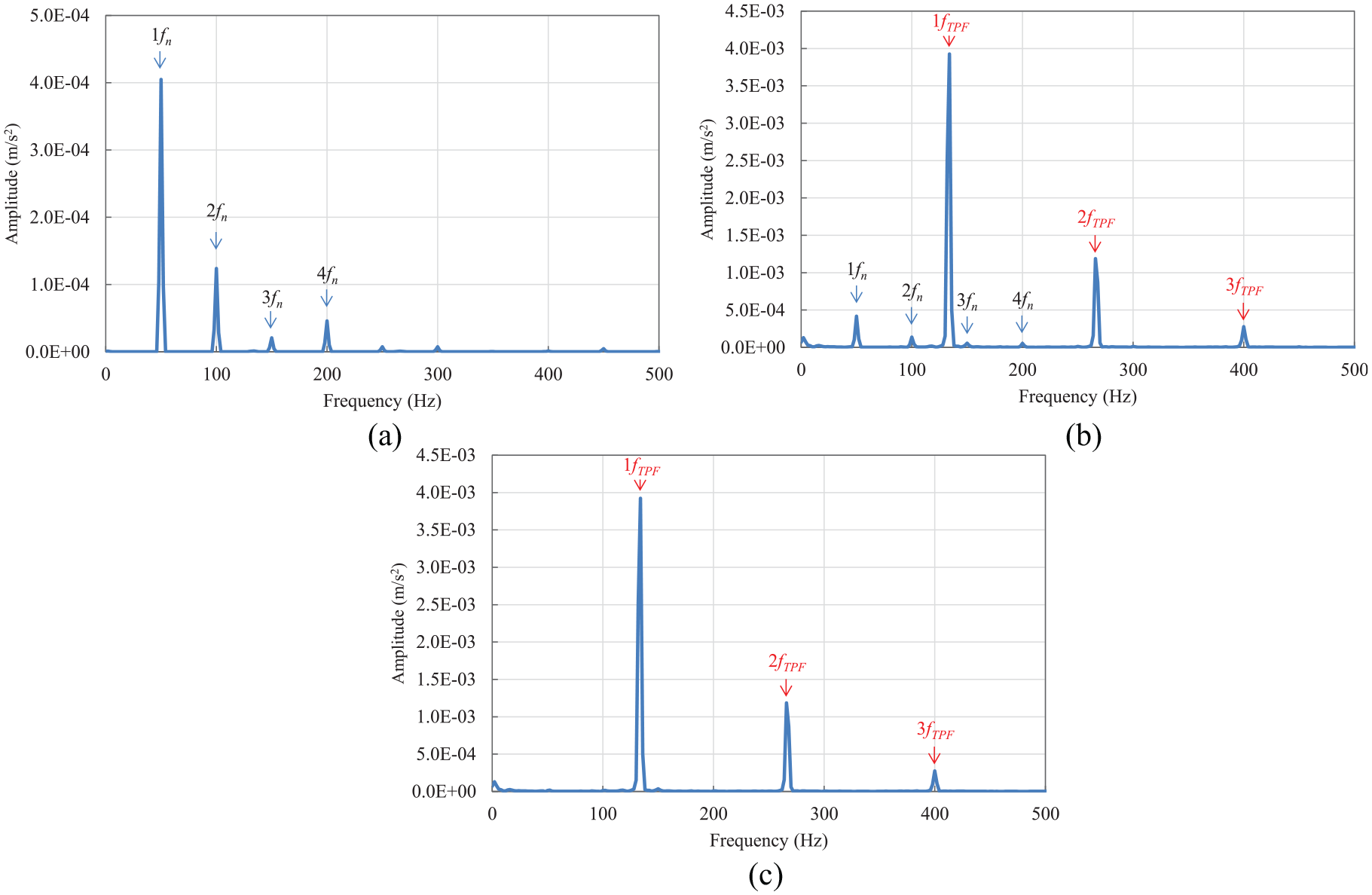
Measured vibration spectrum of the workpiece during milling; the vibration spectrum in the horizontal direction is shown. (a) Vibration spectrum of the first step measurement. The workpiece mainly vibrates at the natural frequency of the workpiece–clamping fixture system. Weak higher harmonics (up to 4×) are also visible. (b) Vibration spectrum of the second step measurement. Both the natural frequency and tooth passing frequency are shown. (c) Final vibration spectrum. Only non-chatter vibration frequencies fTPF are observed.
The vibration amplitude corresponding to the tooth passing frequency of the cutting tool fTPE, which is the first peak as shown in Figure 6(c), is employed for assessing vibration of the workpiece. Vibrations measured in the horizontal z-direction are used, which are regarded as the most significant vibration because the direct contact between the cutter relief and the clearance face with the workpiece acts a major source of vibration excitation. Figure 7 shows the measured vibration amplitudes as a function of cutting parameters. It can be observed from Figure 7 that the vibration amplitude reduces with the increasing cutting speed. This is because the cutting temperature gradually increases with the increasing milling speed, which subsequently softens the material and reduces the cutting force, thus decreasing the cutting vibration. 35 On the contrary, increasing either feed rate or cutting depth leads to the increase in vibration amplitude. When the feed rate increases, the milling vibration increases slightly as shown in Figure 7. The increasing amount becomes more obvious at a higher cutting depth. The increase in workpiece vibration caused by the increase in both feed and depth of cut is due to the increase in cutting force caused by the higher amount of material being removed. The results in Figure 7 also suggest that the workpiece vibration might be strongly influenced by the fact that the experiments were performed without coolant.
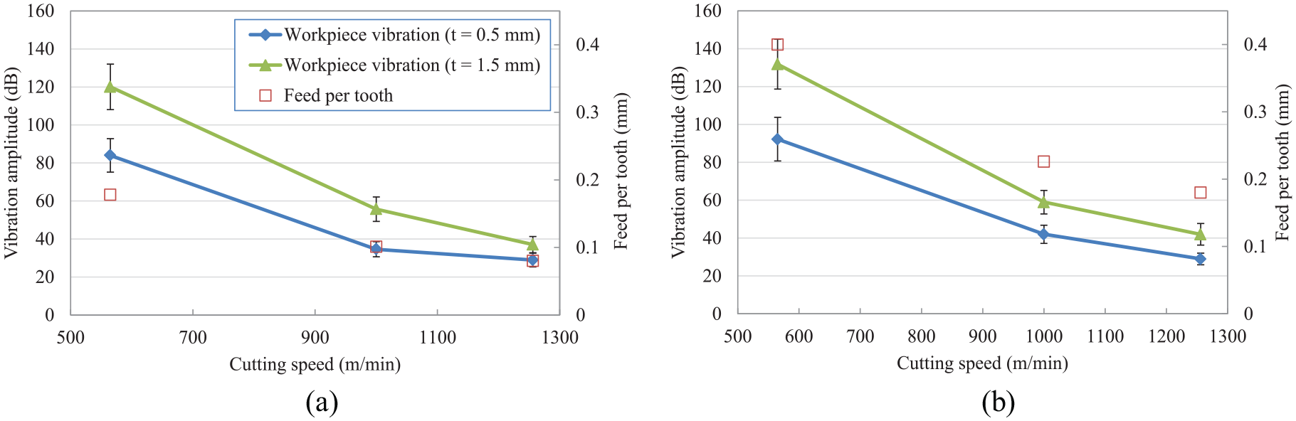
Measured vibration amplitude of the workpiece with varying cutting parameters: (a) f = 800 (mm/min) and (b) f = 1800 (mm/min).
Machined surface roughness
Surface quality of machined parts plays a very important role in engineering. Among the surface quality measures, surface roughness is essential for determining wear resistance, tensile, and fatigue strength of the machined parts. The profile of the machined surface was measured in the feed direction with a surface roughness tester. Figure 8 shows the profiles of the machined surface under different cutting conditions. As shown in Figure 8, a sawtooth shape profile is formed on the machined surface. Moreover, a similar pattern of all surface profiles is generated regardless of the machining condition. The generation mechanism of surface roughness is attributed to the retreat of the cutting edge and the deformation of the tool under the cutting forces. The sawtooth shape profile is generated due to a part of the cutting edge close to the corner retreats more than other areas under a high cutting speed. 36
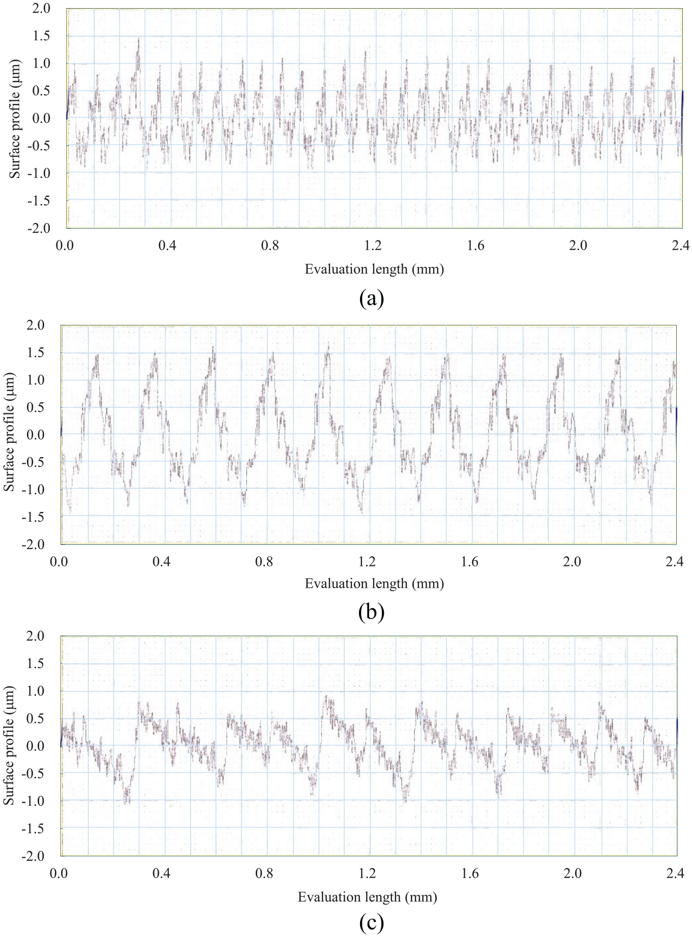
Surface profile of the workpiece generated after milling: (a) V = 1000 m/min, f = 800 m/min, t = 0.5 mm (feed per tooth = 0.101 mm, Ra = 0.42 µm); (b) V = 1000 m/min, f = 1800 m/min, t = 0.5 mm (feed per tooth = 0.226 mm, Ra = 0.64 µm); and (c) V = 1256 m/min, f = 800 m/min, t = 0.5 mm (feed per tooth = 0.080 mm, Ra = 0.39 µm).
Figure 9 shows the effect of cutting parameters on the arithmetic average surface roughness (Ra). It can be seen from Figure 9 that the surface roughness reduces with the increasing cutting speed. This variation trend is similar for almost all cutting tool materials. This is because the increasing cutting speed increases the cutting force and eliminates the BUE formation tendency. The surface roughness deteriorates because more BUE occurs in lower cutting speed machining of aluminum alloys. Deteriorating surface roughness with increasing feed rate can be attributed to the increasing material removal rate.
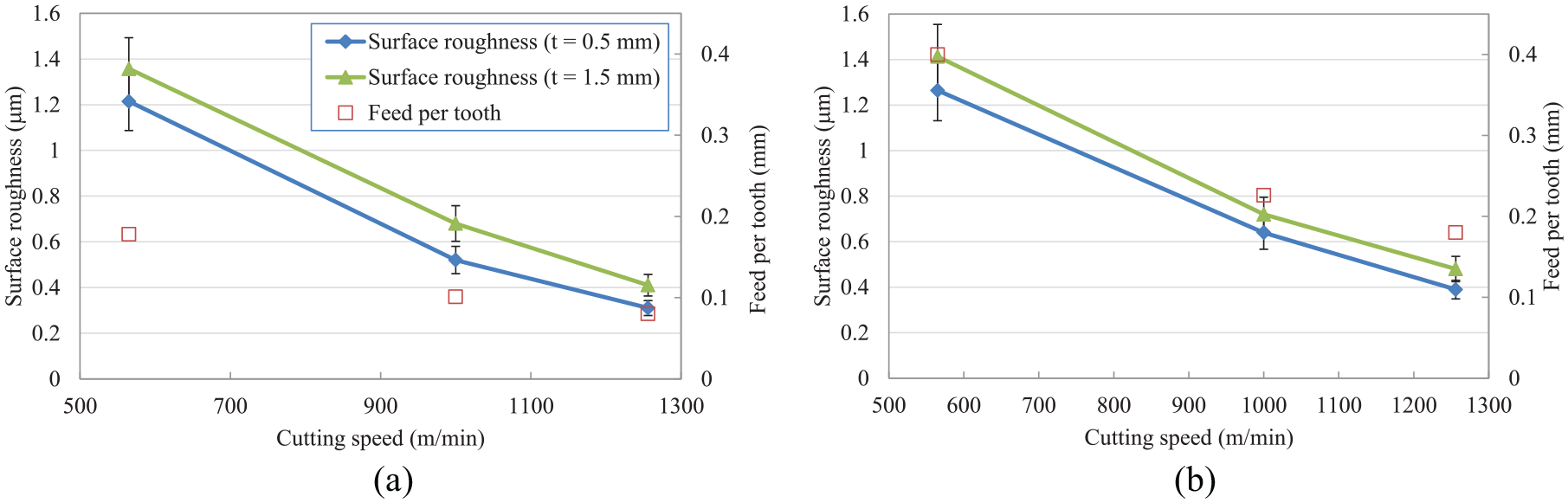
Measured surface roughness with varying cutting parameters: (a) f = 800 (mm/min) and (b) f = 1800 (mm/min).
Conclusion
In this study, an experimental study of high-speed milling of the A6061 aluminum alloy is performed. The influences of cutting parameters on various milling characteristics such as contact length between the tool and the chip, workpiece vibration, chip morphology, and surface roughness are discussed. The following conclusions are obtained from this study:
During high-speed milling, chips with the segmentation geometry are observed. The slide chip surfaces show scratch lines, cavities, and locally deposited molten chip. The chip material gets adhered to the cutter edge after machining.
The tool–chip contact length, workpiece vibration, and surface roughness are all reduced with the increase in cutting speed. On the contrary, they are increased with the increasing cutting depth and feed rate.
The experimental results exhibit a significant improvement in milling performance with high-speed milling. The effect of coolant on high-speed milling performance should be considered in future work.
Footnotes
Acknowledgements
The authors would like to thank the editors and reviewers for their suggestions and comments on the paper.
Declaration of conflicting interests
The author(s) declared no potential conflicts of interest with respect to the research, authorship, and/or publication of this article.
Funding
The author(s) received no financial support for the research, authorship, and/or publication of this article.