
Abstract
Conventional metal cutting processes involve massive consumption of energy where the specific cutting energy is usually high. A major division of this energy is converted into heat, which creates detrimental effects on cutting tool wear, surface quality of machined workmaterial and dimensional accuracy. Although cutting fluids are effective to coerce this energy transfer, the growing challenge to deal with the environmental and health aspects stood by coolant machining is imposing manufacturers to limit the usage of cutting fluids in current metal cutting practice. This research work introduces a new cutting tool, namely, electrostatic micro-solid lubricant–coated carbide tool with molybdenum disulfide as a solid lubricant. To exploit efficacies of newly developed electrostatic micro-solid lubricant–coated cutting tools in comparison with the uncoated cutting tools in machining processes, cutting forces, tool wear, chip formation and surface finish of machined workmaterial have been practically investigated. The results revealed that electrostatic micro-solid lubricant–coated tools performed much better as compared with that of machining with uncoated tools, and the adeptness of the electrostatic micro-solid lubricant–coated tools can make a potential alternative with additional benefits of being able to accomplish sustainable machining.
Keywords
Introduction
Turning operation is one of the most important and widely used material removal techniques in manufacturing industries. The influence of heat generation and frictional effects on contact surfaces during the machining process becomes subject of concern as they have considerable impact on machining efficiency, product quality and productivity. Effective lubrication in machining is essential to safeguard temperature levels do not become excessive. Cutting fluids have extensively been used in conventional cooling, flood cooling and near dry machining, raising, however, severe environmental and economic panics.1,2 Furthermore, cutting fluid application is not biological friendly; as the workers are continuously exposed to cutting fluids, they are mostly under impact of toxic fluids, which cause severe health harms such as lung cancer, genetic diseases, respiratory problems including occupational asthma and hypersensitive pneumonia, dermatological disorders such as irritation, oil acne and skin cancer.3,4 In addition to these biological problems, the inappropriate use of cutting fluids destructs ground water, air, soil, agricultural products and food contaminations because of their toxic effects. 5 Therefore, the growing demand to achieve sustainable machining objectives, that is, societal demands (cleaner, healthier and safer machining), is going to entail the use of alternative machining approaches to avoid or limit the consumption rates of cutting fluids.6–11
Effective countermeasures without the use of cutting fluid (dry cutting) in control of the above effects are strongly required in machining process. It is believed that any change in the contact conditions, as a means of better control over frictional interaction, results in a change in the tool–chip contact and mechanics of machining, thereby influencing the contact temperatures, tool wear, cutting forces and energy consumption. 1 This change is coupled with the requirement of improvement in cutting tool designs and tribological properties. Such improvement on cutting tools can be achieved in three different routes: (1) by using new cutting tool materials, (2) by adapting new cutting tool geometries and (3) by applying hard and/or soft lubricant material coatings on cutting tools. 12 Among these possible strategies, the assistance of solid lubricant as one of the self-lubricating alternative materials on cutting tools in current metal cutting practices has received recent attention because the solid lubricant is safe, clean and nontoxic that requires no expensive discard and can significantly enhance the machining process performance.
Solid lubricant coatings are widely employed to offer an alternative for modifying the tribological component surface properties in a wide range of manufacturing applications, primarily for wear resistance, thermal barrier and to make the machining a pollution-free environment. Advancement in modern tribology is increasingly paying attention on the selection of ecological solid lubricant materials such as molybdenum disulfide (MoS2), WS2, CaF2, graphite, hexagonal boron nitride (HBN), polytetrafluoroethylene (PTFE), TiN, TiC, diamond-like carbon (DLC) and TiB2, which can allow minimum frictional effects and control heat generation between rubbing surfaces in contact. 13 Transition metal dichalcogenides such as MoS2 and WS2 are among the most available and widely studied self-lubricant materials owing to their lubricity and layered crystal structure. 14 The low friction characteristics of these materials have been attributed to their anisotropic hexagonal layered structure with strong covalent bonds between M and X atoms (M=Mo, W; X=S) within a lamella, while adjacent lamella interact through relatively weak Van der Waals forces.15,16 This feature, MoS2 basal layer sliding and its weak Van der Waals forces interaction along the [002] plane, makes MoS2 one of the most promising self-lubricating material used in machining applications.
Over the past few decades, in search of new and further wear-resistant cutting tool materials, researchers and manufacturers have made significant advances through the development of techniques and methods for being used to produce solid lubricant coatings onto tribological components. Every technique has its distinctive advantages and its own application area, but not all of them are suitable for tribological applications due to their poor bonding strength, deposition rate, achievable coating thickness, cost and so on. The most common deposition methods employed in tribological coatings include flotation process, electrochemical deposition, dispersion (dipping, brushing), burnishing, bonding, particulate deposition (thermal spray) and vapor deposition. These deposition techniques allow us to prepare various adherent solid lubricant coatings from soft metal lamellar solids such as MoS2 and WS2 to hard metals such as cubic boron nitride (CBN), TiN and DLC. However, even if these diversified solid lubricant coatings can be achieved using the above-mentioned deposition techniques, there are still some challenges connected to the deposition of micron-size/nano-size particles as they have an extremely high surface area-to-volume ratio, leading to diffusion at high temperatures, often resulting in aggregates and agglomerates rather than a single primary particle. 17
Owing to its economic and simple in-house setup, high transfer efficiency and especially easy deposition on large and geometrically complex surfaces with high deposition rate and coating thickness, the application of electrostatic charging technique makes researchers extremely attractive to use in machining applications.18–20 The authors of the above work are successful in employing such technique and demonstrating the benefits of this approach in enhancing the machining process performance.
Literature review emphasized that the concept of electrostatic charging and its importance exist in some industrial powder coating applications; to the authors’ knowledge, still this technology is new in machining applications and the level of details provided in machining applications is not enough for understanding the benefits of such concept in deposition of micro/nano particles on cutting tools. In this context, in search of economical and environmentally compatible lubrication approach for machining operation, and to look into the feasibility of new coating materials and methods, this research work contributes to the development of the new solid lubricant–coated cutting tools, namely, electrostatic micro-solid lubricant (EMSL)–coated tools, using MoS2 as a solid lubricant. To endorse the performance of developed coated cutting tools, turning experiments were conducted on the aerospace workmaterial, aluminum alloy, AA7075-T6, on commercial high-precision lathe machine and the results in terms of cutting forces, tool wear, chip formation and surface finish of machined workmaterial were compared with that of uncoated cutting tools. The results are expected to be possible avenues to cater the present industrial requirements and can provide a way to make machining a pollution-free environment (sustainable machining).
Experimental procedure
Materials
MoS2 solid lubricant used in preparation of EMSL-coated cutting tools was obtained from Dow Corning Corp., UK, and supplied by Prabha Trade Impex Pvt Ltd, India, in highly refined and purified form with a mean particle size of about 0.6 µm. To enhance the coating adhesion to cutting tool substrate, the pure modified micron-sized phenolic novolac resin powder was used in composition with the solid lubricant. The workmaterial used in machining tests was aluminum alloy, AA7075-T6, which is widely used in transport applications including marine, automotive and aviation applications, due to its high strength-to-density ratio. In machining tests, commercially available SNMG 120408 carbide cutting tool inserts were used and mounted on a commercially available ISO standard tool holder. The composition and element limits for these materials were chosen according to the requirements of standards and were requested from material suppliers accordingly.
Preparation of EMSL-coated carbide cutting tools
Cutting tools used in this study were developed from the newly built EMSL coating deposition experimental system (Figure 1). The system comprises a high-voltage (HV) generator with air/solid lubricant pressure controls, lubricant container, electrostatic spray nozzle assembly and air compressor. These components are connected by hoses and cables and all the necessary regulators and fittings. The purpose of air compressor is to fluidize the solid lubricant particles by passing air through the lubricant container and then to transport the same to the electrostatic spray nozzle.
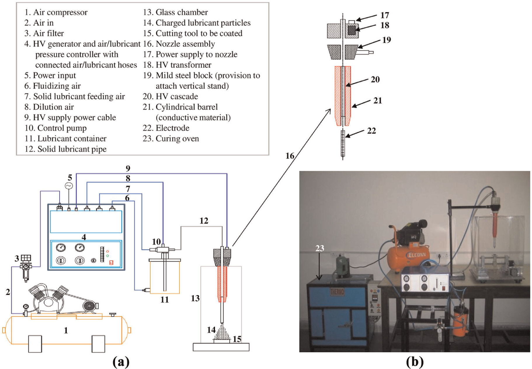
EMSL coating deposition experimental setup: (a) schematic view and (b) photograph of the developed system.
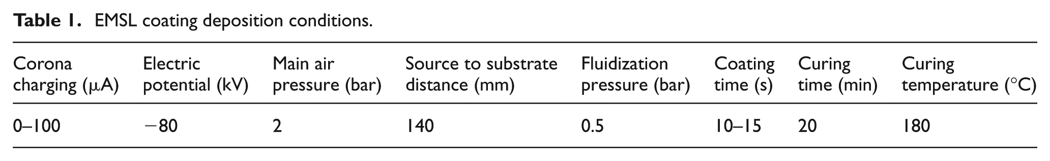
The system makes use of a corona charging principle (low amperage field) to impart the electrostatic charge to the solid lubricant particles passing through comb-like corona charging device, located at the tip of the nozzle. A HV in the range of 0–100 kV is applied to the nozzle to create a required electrostatic force within the sprayed particles. The electrostatic field created at the tip of the nozzle serves to ensure the charging of powder particles owing to ionized airflow in the stream, and consequently, the in-line air supply through nozzle provides easy transfer of particles toward the grounded specimens. The lubricant flow is regulated by controlling the air supplied to the lubricant container. To avoid lubricant particles to mix with air, the coating deposition system is enclosed in a glass chamber. After the deposition of solid lubricant particles onto cutting tool substrates, a convective oven was employed to cure the temporarily adhered solid lubricant particles and to form continuous films that permanently adhered to the substrate. All the EMSL coating deposition conditions are listed in Table 1. Figure 2 shows the photographs of the coated cutting tool specimens and microscopic image of the corresponding coated surface.
EMSL coating deposition conditions.
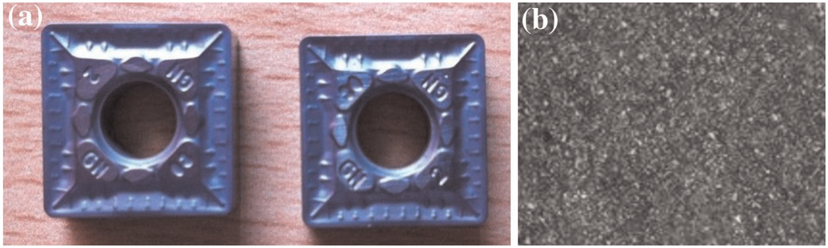
(a) Photograph of the EMSL-coated cutting tools used in turning tests and (b) microscopic image of the coated surface corresponding to (a).
Machining tests
The turning experiments were performed on a commercial high-precision lathe machine at different cutting speeds (vc = 150, 175, 200, 225 and 250 m/min) under a constant feed (f = 0.2 mm/rev) and depth of cut (ap = 2 mm). The ISO standard SNMG cutting tool inserts, characterized by a rake angle γ = −6°, clearance angle α = 6° and nose radius re = 0.8 mm, were used all over the machining tests. All the turning experiments were carried out on a cylindrical workmaterial with initial values of length and diameter equal to 500 and 55 mm, respectively. Two different machining test environments were chosen are as follows: (1) machining with EMSL-coated tools and (2) machining with uncoated tools. Each machining test was conducted for 15 min for all the cutting speeds considered. Each experiment was repeated three times at every cutting condition, and the average of three measurements was used to represent the performance parameters such as cutting forces, tool wear, chip formation and surface finish of machined workmaterial. After completion of each experiment under specified cutting conditions, surface finish on the machined workmaterial was measured using a surface profilometer (Taylor Hobson Surtronic S25). The cutting force and feed force were measured with a strain gauge dynamometer. Cutting temperatures at the tool–chip interface were measured with the help of a thermal infrared (IR) imaging camera (FLIR E60) with 320 × 240 pixels having thermal sensitivity less than 0.05 °C at 30 °C. The chip thickness and tool wear of cutting tools were analyzed using tool maker’s microscope (Olympus STM6) and scanning electron microscope (SEM). A schematic view of the experimental setup for orthogonal machining with a sample measure of chip–tool rake contact temperature using thermal IR imaging camera is shown in Figure 3.
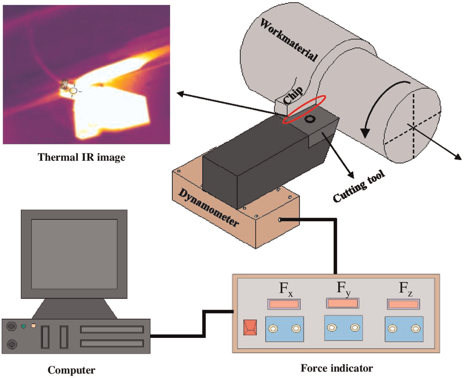
A schematic view of the experimental setup for orthogonal machining with a sample measure of chip–tool rake contact temperature using thermal IR imaging camera.
Results and discussion
Machining process efficiency directly relies on the ability of cutting tool in arresting the frictional influences, contact temperatures, tool wear, cutting forces and energy consumption during cutting process and ensuring they do not become unwarranted. Thus, in order to assess the performance of the developed EMSL-coated cutting tool, an attempt has been made in comprehending its results on tool wear, chip formation and surface finish of machined workmaterial. Machining performance as assessed by the above parameters has long been recognized as they have considerable impact on the productivity, product quality and overall economy.
Cutting forces
The cutting force (Fc) and feed force (Ff) are measured in the direction parallel and perpendicular to the relative velocity of the cutting tool and workmaterial. The effect of cutting speeds on cutting and feed forces in turning of AA7075-T6 with and without coated tools is presented in Figure 4(a) and (b). It was observed that the cutting speeds were found to have a significant effect on the forces. In both the machining, forces decrease when the cutting speed increases, while variation in these forces during machining with EMSL-coated tools seems to be quite steady and are lesser as compared to those forces found during machining with uncoated tools. Also, the performance of the EMSL-coated tool is the most obvious and was reduced the forces by on average of 15% in tested conditions. This is due to the fact that as the presence of MoS2 film exists on tool face, the friction on the tool–chip interface zone is reduced and thus the cutting force is reduced.
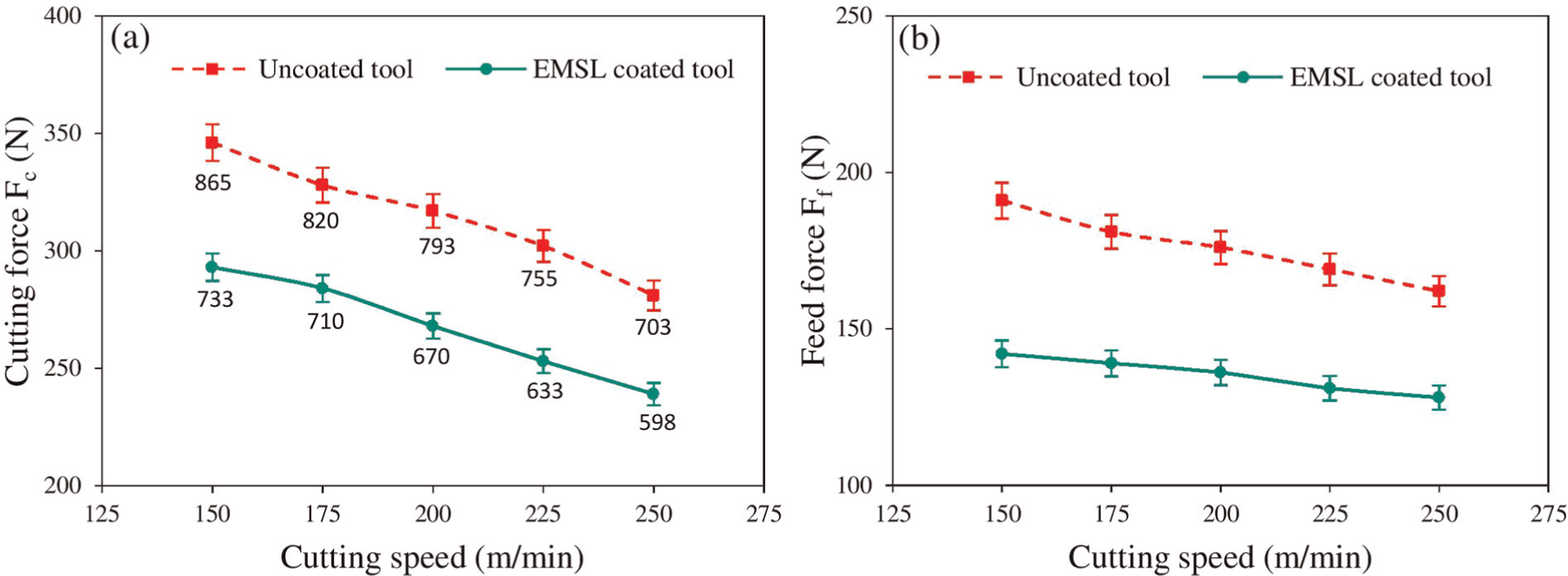
(a) Cutting forces with induced specific cutting energy (us) (see data point values) and (b) feed forces measured during machining with and without coated cutting tools.
Measured horizontal force (cutting force) and vertical force (feed force) on the tool rake face are usually transformed in the direction of primary motion and feed motion, that is, to the normal force (N) and friction force (F) in orthogonal cutting. Based on the geometric parameters of orthogonal cutting, the average coefficient of friction (µ) between the tool and chip can be calculated using equation (1)
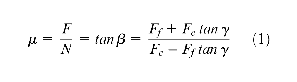
where β is the friction angle and γ is the rake angle.
The specific cutting energy, us, which represents the energy consumed in removing a unit volume of work material, is calculated from equation (2)

The effectiveness of EMSL-coated tools in minimizing the frictional effects at the tool–chip interface is evident from Figure 5. The lower values of coefficient of friction (reduction by 14%−16%) during machining with EMSL-coated tools in all the tested conditions could be related to two phenomena: (1) decrease in specific cutting energy in the tool–work interface (see Figure 4(a)), and (2) lower cutting temperatures (Figure 6). In the first case, one can see that the reduction in the specific cutting energy induces the lower cutting forces with EMSL coatings due to the existence of MoS2 on tool face and its easy shearing action between chip–tool rake face, which may contribute to the decrease in the coefficient of friction. Furthermore, the decrease in cutting temperatures at all cutting speeds (reduction by 14%−18%) is directly dependent on the self-lubricant coating on cutting tools, which was transferred and acted as lubricating additive between the tool–chip–work interfaces.
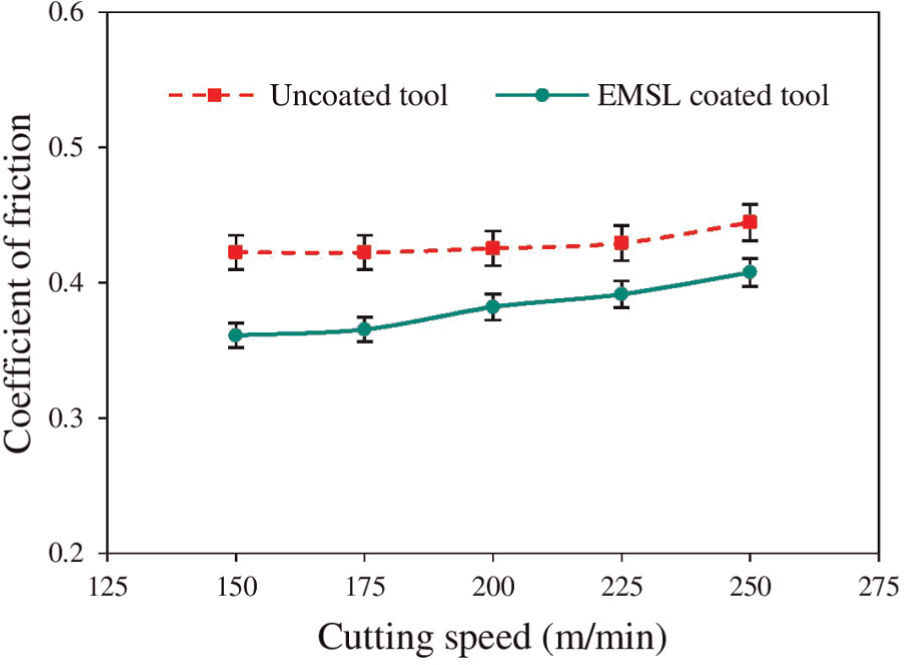
Coefficient of friction calculated during machining of AA7075-T6 with and without coated cutting tools.
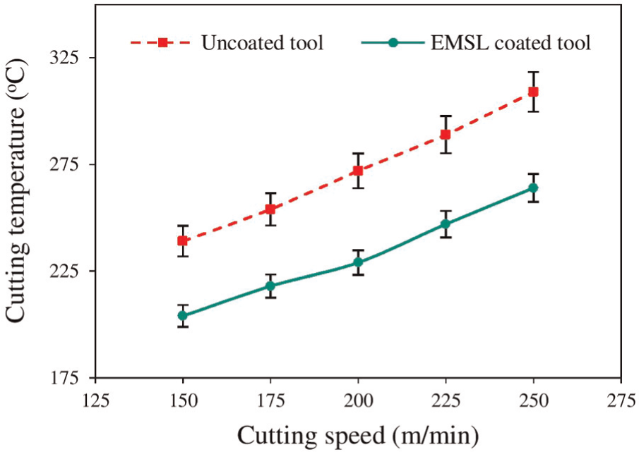
Cutting temperatures measured during machining with and without coated cutting tools at various cutting speeds.
Tool flank wear
The average flank wear of tools in both the machining at different cutting speeds and wear growth at particular cutting condition as the function of cutting length is shown in Figure 7. It is indicated that the tool flank wear of both coated and uncoated tool was increased steadily with increase in cutting speed at all tested conditions (Figure 7(a)). Furthermore, EMSL-coated tools exhibited much superior ability in maintaining the wear resistance during the entire tool life than that of the uncoated tool (Figure 7(b)). The results reveal that within the tested experimental conditions, almost on average of about 25% less tool flank wear occurred with EMSL-coated tools when compared to that of uncoated tools. This can be due to the following tendency: (1) decrease in the specific cutting energy on average of about 15% (Figure 4(a)) due to the presence of MoS2 film on the tool face and (2) decrease in cutting temperatures on average by 14%−18% (Figure 6) in all tested conditions owing to transfer of self-lubricant film to the tool–work interface. So, it implies that MoS2 solid lubricant can work effectively as a self-lubricating material on cutting tools. In this study, the flank wear results on the uncoated carbide insert were found to be more or less nearer to the results found in previous studies. 21 The observed differences in flank wear values could be due to the differences in selected cutting conditions and testing environments.
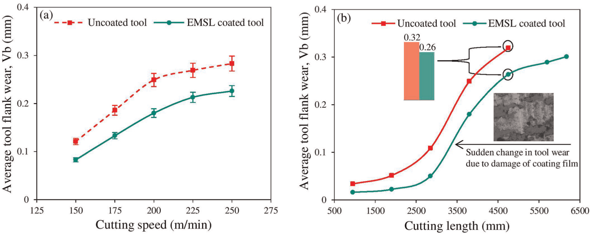
(a) Comparison of average tool flank wear under various cutting speeds and (b) wear growth at particular cutting speed (200 m/min) against cutting length in machining with and without coated cutting tools.
The wear characteristics of the cutting tools have been substantiated and scientifically observed through the features of worn surfaces. In order to see the wear growth on the cutting tools, especially in EMSL-coated tools, a SEM analysis was performed. Figure 8 presents the SEM micrographs of worn surfaces of coated cutting tools used in turning of workmaterial at particular cutting conditions. Examinations of the worn surfaces (Figure 8(a)) revealed that the built-up edge (BUE) on the cutting edge was predominant at lower cutting speeds. This could be mainly due to adhesion of the machined workmaterial on the cutting tool surface. With high plastic deformability due to large shear strains within the primary shear zone, aluminum alloy has a high tendency to adhere with the cutting tool material and results in high BUE. Furthermore, cutting temperatures associated with relatively high cutting speeds result in very less BUE and ending with high tool wear (Figure 8(b) and (c)). The energy-dispersive spectra (EDS) chemical composition analysis on the worn surface (Figure 8(d)) is an indication for the above and confirms no self-lubricating material elements were seen on the worn surface.
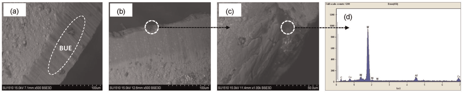
(a) BUE formation on the tool cutting edge at 150 m/min speed, (b) flank wear on the tool surface at speed 200 m/min, (c) magnified view corresponding to (b) and (d) EDS chemical composition analysis on the worn surface corresponding to (c) during machining with coated cutting tools.
Chip formation
The form of chip produced in a machining process is one of the most important parameters as it influences the surface finish, workpiece accuracy and tool life, thereby affecting productivity and product quality. Hence, the production of an acceptable form of chip is essential in metal machining. According to ISO 3685 standard, chip shapes during a machining process can be classified into several types, which can be in either acceptable form or unacceptable form. Acceptable chip forms (short tubular, washer type, spiral and arc shape) can move easily from the machining zone and do not interfere with the machined surface quality. In contrary, unacceptable chips (ribbon, tangled and needle type) can influence the quality of the machined surface as they tend to tangle around the tool and the workpiece and pose safety problems to operators. Figure 9 shows some of the chip shapes obtained during machining with and without coated tools under different cutting conditions.
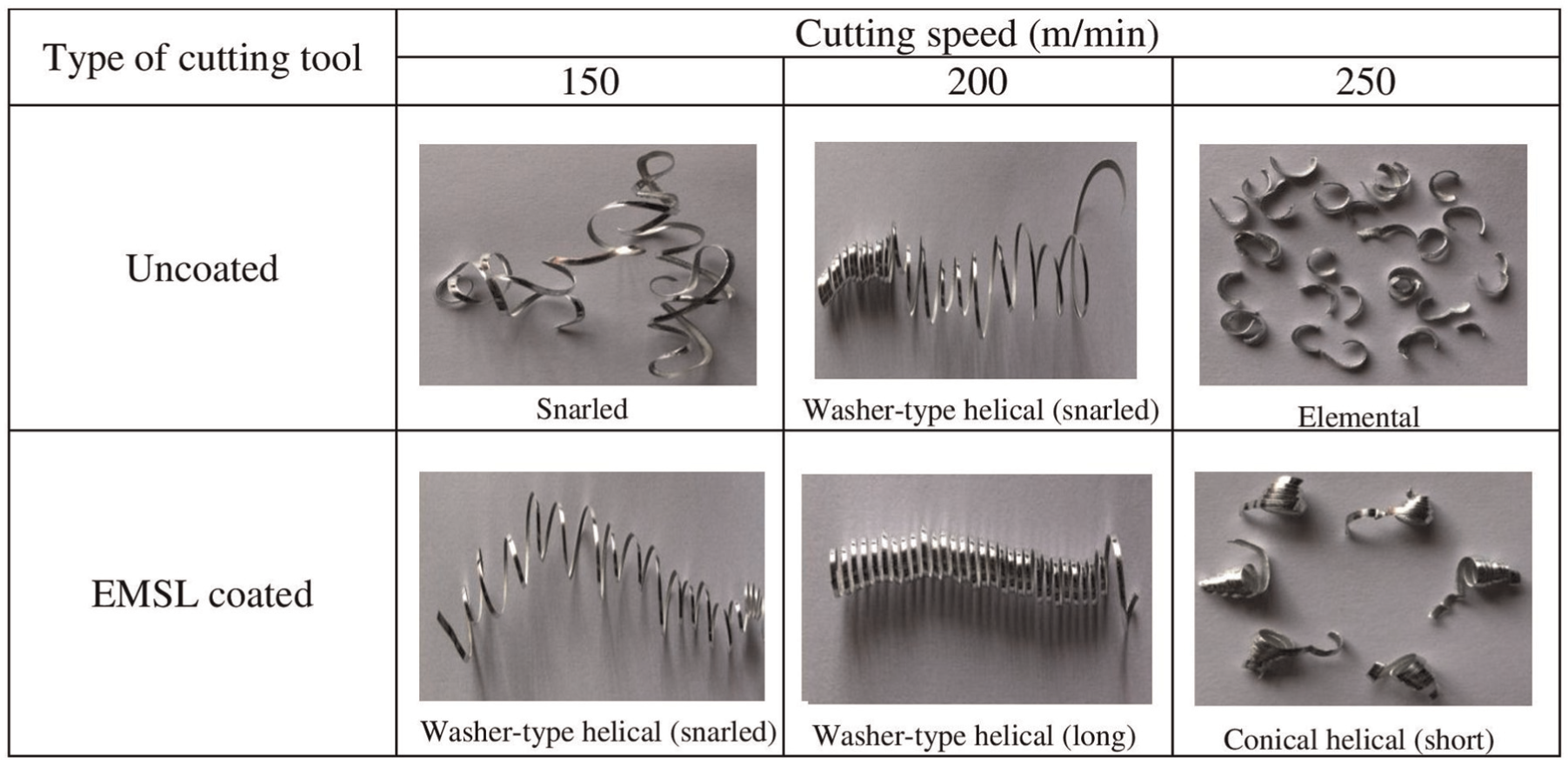
Comparison of chip shapes during machining of AA7075-T6 with and without coated cutting tools.
The chip reduction coefficient, which is calculated as the ratio of chip thickness to the uncut chip thickness, is the prime parameter in knowing the shear plane angle and determining the cutting process efficiency because it reveals the energy spent during plastic deformation of workmaterial. The chip thickness and chip reduction coefficient during machining with and without coated tools were measured and found to be less in the case of machining with EMSL-coated tools. This improvement is because of the high shear plane angle (Figure 10(a)) due to better lubrication by the presence of solid lubricant film on the rake face of the cutting tool. The gap between the lines in Figure 10(a) is an indication for the above improvement. The chip formation showing shear deformation to form chip and its shear plane angle during machining with EMSL-coated tools is presented in Figure 10(b).
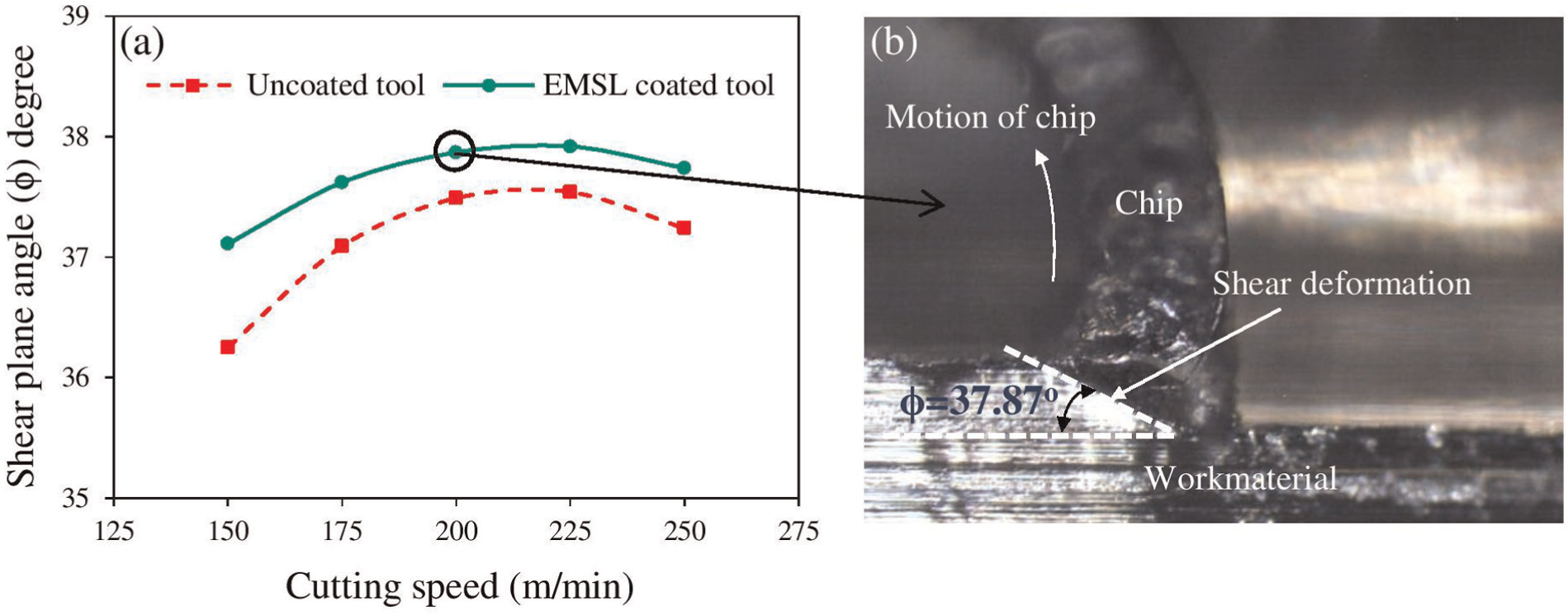
(a) Variation in shear plane angle to form a chip at different cutting speeds and (b) chip formation showing shear deformation (shear plane angle, φ = 37.87°) corresponding to vc = 200 m/min during machining with coated cutting tools.
Surface roughness analysis
Surface roughness is an important index not only in predicting the surface quality of machined workmaterial but also in influencing the performance of mechanical parts and production costs. The degradation of surface quality often depends on the machining process performance, including selection of cutting conditions, lubricants and the effectiveness of the cutting tool materials. Any improvement in tool–workmaterial interaction by reducing the frictional effects on contact surfaces by proper selection of cutting tool material will affect the surface quality and the tool performance to a greater level. In this work, an attempt was made to see the effectiveness of EMSL-coated tools on the quality of machined surface.
Figure 11 shows variations in the average surface roughness (Ra) as a function of cutting speed during turning of AA7075-T6. It is observed that the values of surface roughness during machining with EMSL-coated tools are always smaller, and surface quality of workmaterial under this machining showed a much better improvement by 20% when compared to that of machining with uncoated one. This is expected because of the following two phenomena: (1) at higher cutting speeds, the BUE on cutting tool surface turns out to be less (Figure 8), chip breakage decreases and hence the quality of machined workmaterial surface and (2) presence of MoS2 can reduce cutting temperatures generated and prevents further tool wear progression. Surface roughness values in this study are found to be in the same trend as it can be seen in the previous work, 21 where higher cutting speeds result in relatively easier material removal from the workpiece, resulting in a better surface finish on the machined workmaterial.
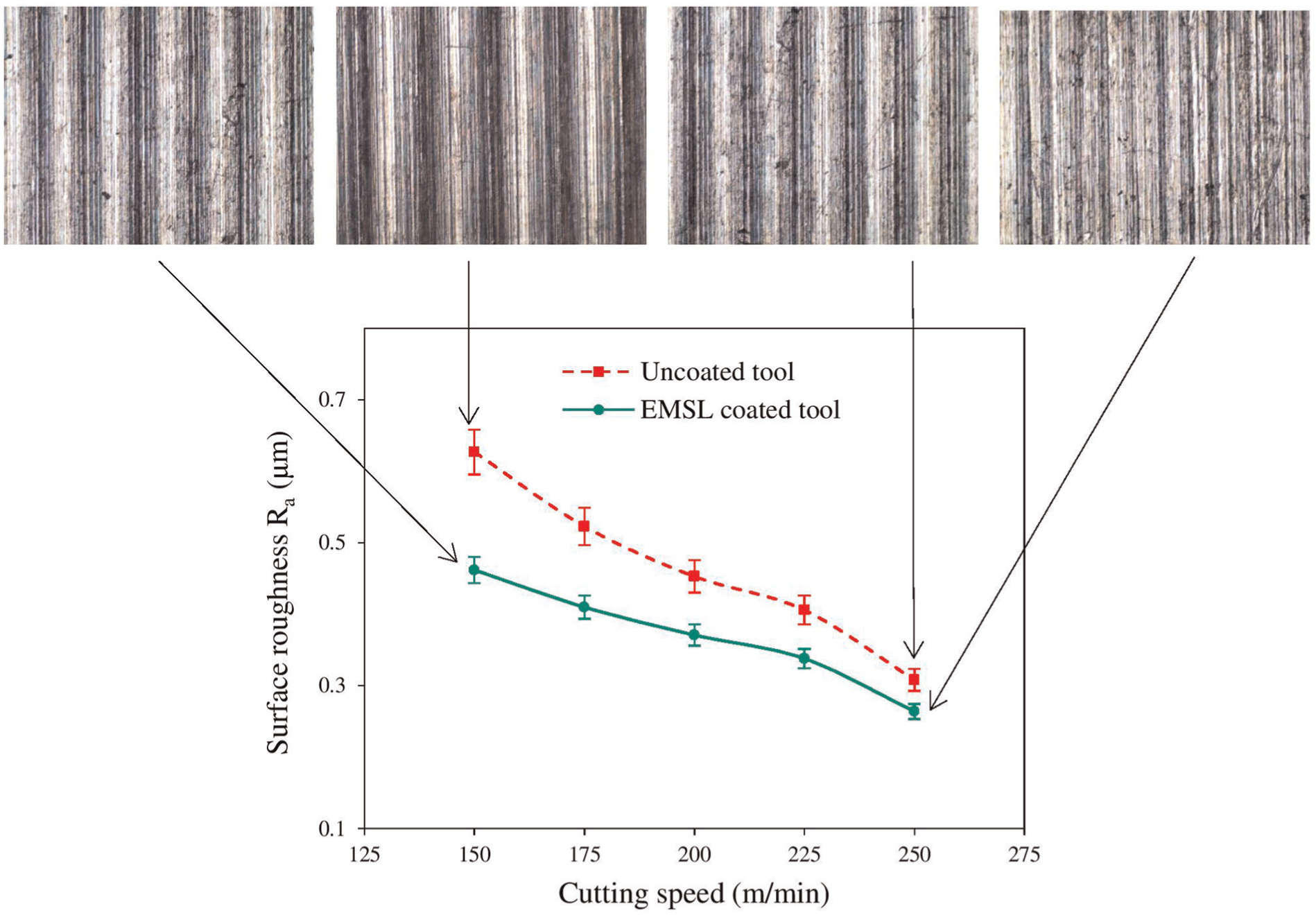
Variation in average surface roughness as a function of cutting speed measured on machined workmaterial during machining with and without coated cutting tools.
Conclusion
The performance of EMSL-coated cutting tools during cutting tests has been demonstrated successfully and the outcome of the study is that the EMSL-coated tools can endow superior process performance compared to that of conventional cutting tools. In summary, EMSL-coated cutting tools demonstrate the benefits in curtailing the tool–chip contact frictional effects and contribute to the favorable control of heat generation at tool–workmaterial contacts. This is because of the lamellar structure orientation of MoS2, which shears easily along the chip–tool rake face sliding direction leading to such favorable benefits. Machining with EMSL-coated tools results in lower specific cutting energy due to thermal softening at tool–work interface leading to reasonable lower cutting forces (15% less) than those in machining with uncoated tools under same cutting conditions. As a result of lesser cutting forces and temperatures, average tool flank wear in EMSL-coated cutting tools is very less on average by 25% as compared to that of the uncoated one. The formation of BUE on coated cutting tool edge is found to have a significant effect on the quality of machined surfaces. It is true because as the cutting speed increases, the adhering tendency is low and the BUE becomes sparse and chip fracture decreases, and hence, surface quality improves (20% higher). Shear deformation to form chips under all experiments was judged and observed favorable tool–chip interaction in machining with EMSL-coated tools. This is true because lower cutting temperatures due to the existence of MoS2 on the tool surface can lead to higher shear deformation.
In a future work, various solid lubricant material combination effects may be incorporated to the current approach in order to increase the process performance to further level, especially with different tool–workmaterial groups under varying cutting conditions. The implementation of the same should extend the validity of this work before finding its greatest use in various machining applications.
Footnotes
Acknowledgements
The authors would like to extend their thanks to all supports needed for this study.
Declaration of conflicting interests
The authors declare that there is no conflict of interest.
Funding
The authors gratefully acknowledge the support of Council of Scientific and Industrial Research (CSIR), New Delhi, India, through project grant 22(0567)/12/EMR-II.