
Abstract
A membrane electrode assembly is the core component of a proton-exchange membrane fuel cell stack. It consists of multilayer structured membranes which are flexible, heterogeneous and have variable cross section. To improve the efficiency of membrane electrode assembly processing and manufacturing, a roll-to-roll system with gas diffusion layer is designed. By peeling the protective membrane and the upper and lower gas diffusion layers’ hot-pressing, proton-exchange membrane is manufactured into a five-layer catalyst-coated membrane. Then, the catalyst-coated membrane is manufactured into membrane electrode assembly by multilayer membrane breakpoint die-cutting and laying-off. The system integrates multiple key technologies, including roll-to-roll precise feeding, gas diffusion layer multi-degree accurate operation and multichannel temperature control, to realize the precise positioning of flexible multilayer membrane and brittle gas diffusion layer. The tension inhomogeneity and critical wrinkling tension are modeled for web traveling in the continuous roll-to-roll manufacturing equipment. The proposed roll-to-roll stack and lamination system effectively combines discontinuous hot-pressing, die-cutting, laying-off technics to realize the high-efficiency manufacturing of membrane electrode assembly.
Keywords
Introduction
The fuel cell (FC) converts chemical energy directly to electricity with low emission of pollutants, high power density and quiet operation.1–3 There are plenty kinds of FCs,4,5 among which proton-exchange membrane fuel cell (PEMFC) is a new type of clear-energy FC. The fuel of PEMFC is hydrogen and the charge carrier of it is hydrogen ion (proton). Hydrogen molecule decomposes into hydrogen ions (protons) and electrons at the anode. Hydrogen ions penetrate the electrolyte into the cathode, while electrons flow through the external circuitry and generate electricity. After reaching the cathode plate, the electrons recombine with oxygen and hydrogen ions to form water.6–8
A membrane electrode assembly (MEA) is the heart of a PEMFC stack. 9 It consists of proton-exchange membrane (PEM), seal membrane, catalyst layer (CL) and gas diffusion layer (GDL). 10 The nature of PEM determines the structure and main technical characteristics of PEMFC. At present, the inefficient artificial production is largely used in MEA manufacturing, 11 and therefore it is urgent to improve production efficiency by utilizing automatic equipment.12,13 A roll-to-roll (R2R) stack and lamination equipment was designed to accomplish the efficient stack and lamination of PEM and seal membrane in MEA manufacturing. 14
Continuing the study by Chen et al., 14 this article presents a fully automatic continuous R2R equipment for GDL overlaying (see Appendix I), which follows the seal membrane lamination process. It is a vital constituent part of the MEA production line. The proposed R2R equipment integrates plenty of key technologies, including R2R conveyance of flexible membrane, efficient picking and placing of loose brittle GDL, precise alignment of multilayer heterogeneous membrane, solidifying connection of brittle membrane material and flexible substrate and breakpoint die-cutting of multilayer flexible membrane.
The design of GDL R2R overlaying system
GDL overlaying technics in MEA manufacturing
There are generally two kinds of processes which have been developed to produce catalyst-coated MEA 15 :
CL is directly coated on PEM to form catalyst-coated membrane (CCM), and then CCM is combined with GDL to form MEA;
CL is deposited onto GDL to form gas diffusion electronic cathode, and then the GDL electrode cathode is heated with PEM to form MEA.
The detailed processes are illustrated in Figure 1.
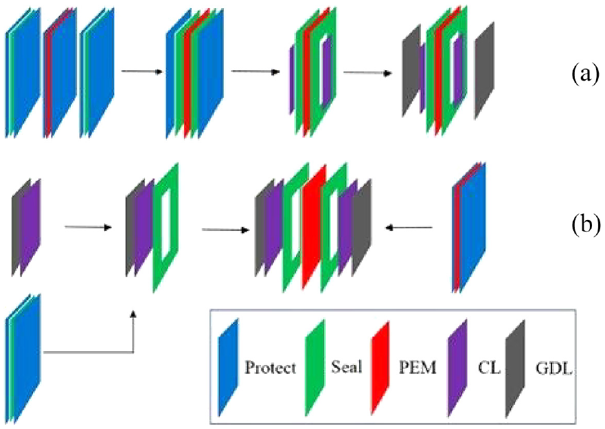
Two kinds of processes in catalyst-coated MEA production line: (a) CL be coated on PEM to form CCM, then CCM combines GDL to form MEA, (b) CL be deposited onto GDL, then GDL electrode cathode heated with PEM to form MEA.
Pt catalyst is coated on PEM in the first process, while it covers the entire GDL membrane in the second process. Considering the GDL membrane has large superficial area, rough surface and it is porous, the latter process will cause huge waste of Pt catalyst. It is not conducive to the cost management of PEMFC production. Therefore, the first process of MEA manufacturing is selected as the research object, and an MEA production line, as shown in Figure 1(a), is presented. In this production line, GDL overlaying equipment is responsible for the last procedure, that is, the lamination of GDL membrane and the laying-off of MEA.
R2R stack and lamination system
R2R system has been proved an efficient and low-cost manufacturing method in the production of solar cell,16,17 flexible display,18,19 and flexible electronics.20,21 The proposed GDL continuous overlaying system adopts R2R stack and lamination technics. The upper and lower protective membranes of CCM are peeled after the seal membrane continuous lamination procedure. Then, GDL membranes and CCM are compressed into compound membrane, which has the GDL-CCM-GDL structure. As shown in Figure 2, the GDL overlaying systems are divided into five functional units to accomplish the whole lamination process:
Peeling the upper and lower protective membranes;
CCM to produce five-layer membrane, that is, Membrane I;
Picking up two pieces of GDL membranes by manipulator successively, going through hot-pressing module to integrate Membrane I with GDL membranes to produce seven-layer membrane, that is, Membrane II;
Cutting Membrane II to form breakpoint discontinuous connection of multilayer membrane;
Collecting MEAs by laying-off module;
Rewinding the waste multilayer membrane by rewinding module.
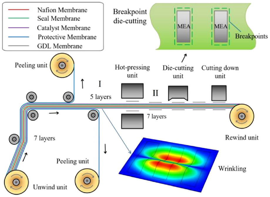
GDL R2R stack and lamination system.
As shown in Figure 2, to ensure the continuity of each process, the structural stability of the transport film should be maintained before collecting MEA product. Therefore, the breakpoint die-cutting technic is introduced in the die-cutting module, which requires continuous breaches on the edge of die-cutting knife to generate notch geometry that is apt to be compressed by laying-off module. In this technic, the precision of the die-cutting depth is undemanding and the proposed technic has little effect on the mechanical strength of the continuously conveying flexible membrane. Thus, it is beneficial to maintain the stability of the conveying membrane.
Traditional MEA manufacturing processes are mostly manual or semi-automatic production, and it is difficult to achieve high efficiency, high quality and consistent production. The adoption of R2R process can effectively overcome the shortcomings of traditional methods. It can realize the automatic transfer of multilayer structural materials and adjust the module production beat of continuous and discontinuous operation in the system to form an organic system with orderly connection.
Analysis of core modules of GDL continuous overlaying equipment
The core modules of GDL continuous overlaying equipment contain GDL manipulator module and hot-pressing module.
GDL manipulator module
According to the requirements of the GDL overlaying function, the GDL manipulator needs five independent degrees of freedom, including three translational motion and two rotational motion. Three servo motors are used to drive precision ball screw for three basic motions along x, y, z axes. β motion, that is, reversal motion of the entire GDL driven by precision oscillation cylinder, supplies GDL to the upper and lower sides of the hot-pressing module. γ motion, that is, angular adjustment motion in x−y plane, is accomplished by precision direct drive module. The real manipulator is shown in Figure 3(a), in which γ motion is achieved by the coordination of direct drive module and restoring spring. As shown in Figure 3(b), the rotation center is located at the end of GDL picking parts.
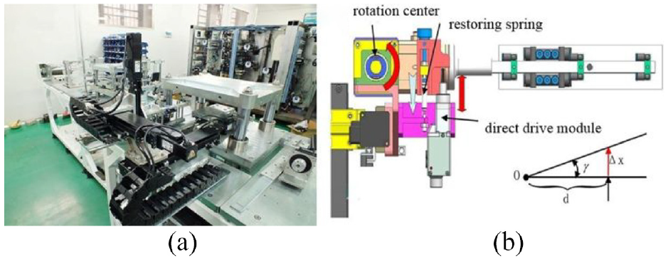
The GDL manipulator: (a) snapshot of real GDL manipulator and (b) schematic diagram of manipulator’s γ motion.
As shown in Figure 3, GDL manipulator adopts vacuum adsorption technics to grab loose porous GDL membrane. It utilizes airflow control method to grab reliably and prevent carbon powder layer from being destroyed. Both operations, grabbing GDL heap and laying GDL on the hot-pressing block, require control of the force which manipulator exerts on GDL. Therefore, force sensors are configured at the end of the manipulator to measure the magnitude of contact force. Then, the feeding position of the manipulator can be controlled.
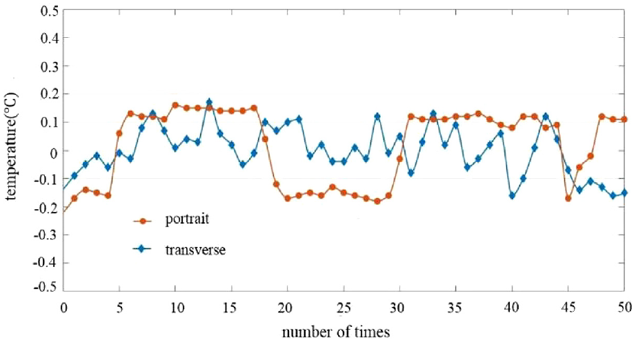
After transferring GDL, lamination of GDL and CL can be realized, and the quality detection of GDL overlaying can be obtained via CCD camera. After being grabbed and laid by the manipulator, the upper and lower GDL membranes will be integrated with CL by the hot-pressing module. According to the images of the location of GDL on the multilayer membrane, the transverse and portrait (the feeding direction) contraposition errors of the upper and lower GDL membranes can be obtained. As shown in Figure 4, the error margin of transverse and portrait contraposition is ±0.2 mm, and the result meets the requirements of the lamination of MEA.
The transverse and portrait contraposition errors of the upper and lower GDL membranes.
Hot-pressing module and temperature control
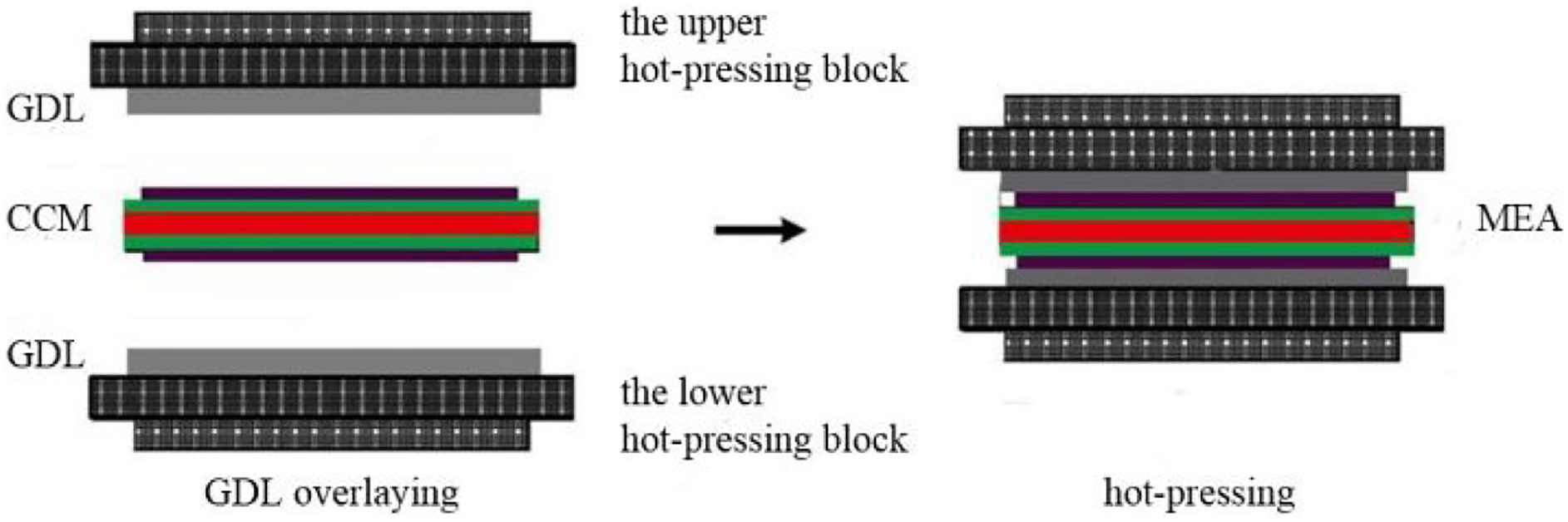
To guarantee the stable lamination of GDL and CL, the temperature and pressure need to be maintained at the designed value for a period of time. The working principle of hot-pressing module is shown in Figure 5.
The working principle of hot-pressing module.
The overlaying technics designed is suitable for GDL membranes of size 201 mm × 34 mm × 0.3 mm. The target temperature is 85 °C, and the pressure is required to be maintained at 3 MPa for 60 s. The snapshot of real hot-pressing module is shown in Figure 6(a) and hot-pressing block is shown in Figure 6(b). The upper hot-pressing block possesses translational degree of freedom along the z-axis and converts weight of the mechanism into part of overlaying pressure. The upper and lower hot-pressing blocks are both equipped with (1) heating core group, which is used to raise temperature; (2) temperature sensor group, to measure the temperature of hot-pressing working surface to accomplish temperature closed-loop control; and (3) vacuum adsorption design, which is adopted to fix manipulator after overlaying GDL.
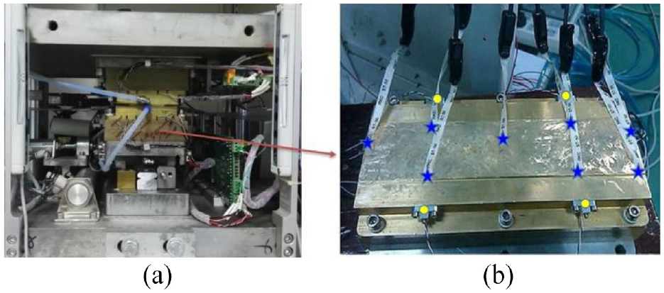
The hot-pressing module: (a) the snapshot of real hot-pressing module and (b) the hot-pressing block and the layout of temperature sensor, where yellow dots represent the location of the temperature sensors in the control loop and blue stars represent the location of eight monitoring temperature sensors.
In order to measure the heat transfer capability and temperature control ability of the hot-pressing block, the temperature control experiment based on the measurement of multiple temperature sensors is carried out. As shown in Figure 6(b), patch temperature sensors are located at eight different positions on hot-pressing block. The temperature of each recording point is constantly monitored by a multichannel data recorder, and the temperature curves obtained are shown in Figure 7.
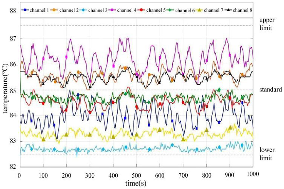
Eight-channel temperature curves of hot-pressing block.
The temperature data show that after reaching thermal equilibrium, the entire temperature of hot-pressing surface is stable at 85 ± 2.5 °C and the temperature of each recording point is stable at ±1.2 °C, which meet the requirements of MEA lamination.
Modeling of tension inhomogeneity and critical wrinkling tension
As shown in Figure 2, the GDL R2R stack and lamination system is complex and the tension distribution and mechanical characteristics of the web are dynamically varying with the traveling, laminating and cross-sectional changing. The modeling of the tension inhomogeneity and critical wrinkling tension is important for the effective operation of the R2R system.
Tension inhomogeneity of the traveling web
In many engineering applications of R2R manufacturing, especially for the GDL lamination system, the inhomogeneity in the tension profile applied at both the ends of web is apparent. In this section, the transverse vibration and instability of axially traveling web subjected to parabolic tension profile are investigated.
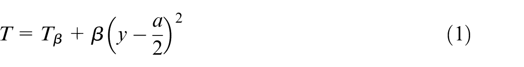
As shown in Figure 8, the traveling web is modeled as an isotropic membrane. The geometric properties of the web are as follows: length is L, thickness is h, width is W and the area is A = LW. Let Young’s modulus be E, Poisson’s ratio be ν and mass density be ρ. The longitudinal, lateral and transverse displacements are denoted by u, v and w, respectively. As the stiffness of in-plane is much larger than the stiffness of out-of-plane for the web, it is reasonable to assume that u and v are steady and w is time-varying. 22 The web is subjected to parabolically distributed tension in the x-direction, which is defined as follows
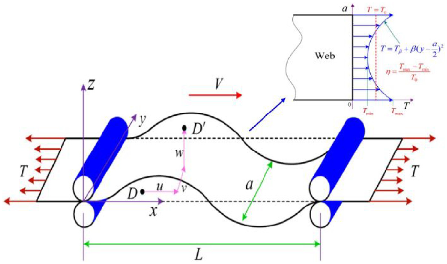
Schematic representation of traveling web between two pinch rollers.
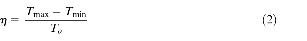
The average value of tension is T0 when the tension profile is homogeneous. So, the inhomogeneity in the tension profile is defined as follows
According to the extended Hamilton principle, the governing equations of motion for the traveling web are derived as follows
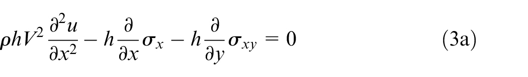
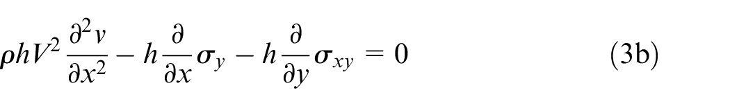
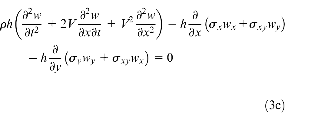
As the lateral and transverse motions are restricted at the boundaries of the x-direction in R2R manufacturing, the boundary conditions of equation (3) at x = 0 and x = L are given as follows

The web is free of traction at y = 0 and y = a, that is
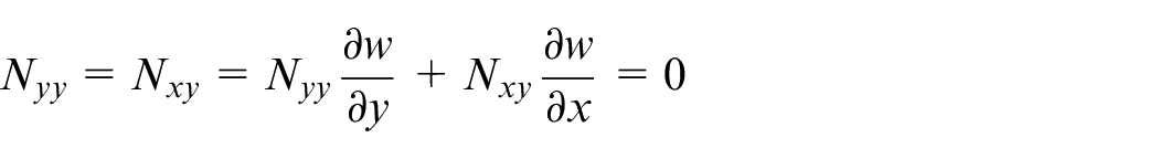
Here, Nxx = hδx, Nxy = hδxy, Nyy = hδy denote the linear stress.
The governing equations can be discretized to a finite dimensional dynamic model by employing the Galerkin method 23 and then the complex natural frequencies and mode shapes of the transverse vibration can be computed.
As shown in Figure 9, the mode shapes of the transverse vibration are completely changed when the tension inhomogeneity η = 0.1. It can be seen that even small tension inhomogeneity can make a great impact on the mode shapes. Figure 10 shows that the in-plane stresses are not uniform when the web is subjected to inhomogeneous tension. The stress value in the neighborhood of the rollers is relatively higher and the web around the rollers may break if a severe vibration occurs.
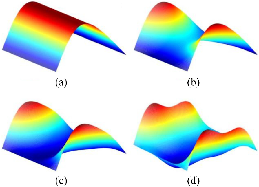
Divergence shapes for variable tension inhomogeneity of the traveling web. The tension inhomogeneity coefficients are as follows: (a) η = 0, (b) η = 0.1, (c) η = 0.5 and (d) η = 1.
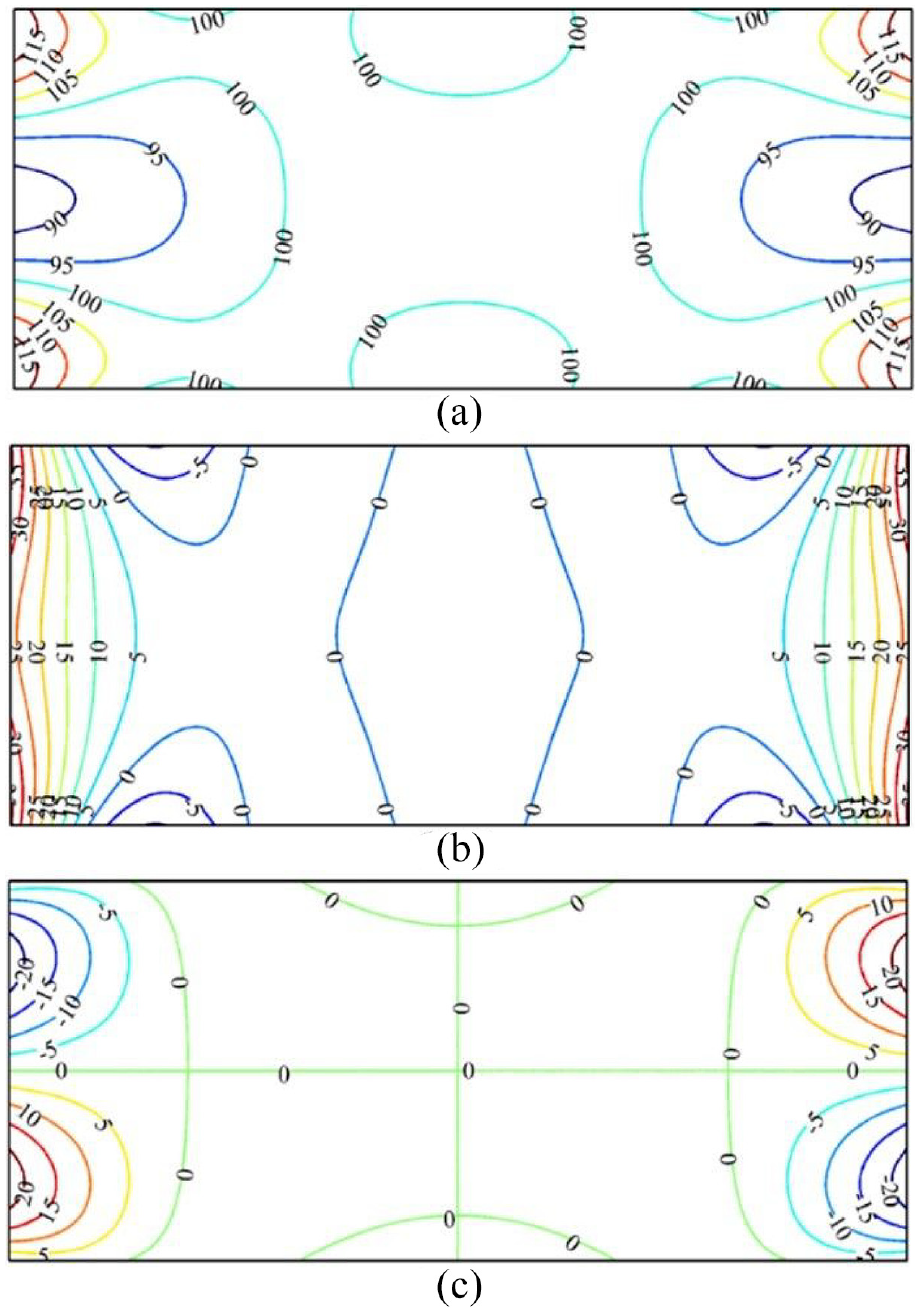
In-plane stress distribution when T0 = 100 N/m, η = 1: (a) Nxx, (b) Nyy and (c) Nxy.
Critical wrinkling tension for web with sub-regions
As shown in Figure 2, the web may become non-uniform after the protective membranes peeled, GDL hot-pressed or breakpoint die-cut. The non-uniform structure can induce local compressive stress in the web, which may cause the wrinkling of the web if the tension of the non-uniform web exceeds a critical value. Thus, it is necessary to clarify the relationship between the critical wrinkling tension and parameters of the web.
The simplified model of the web between two rollers is illustrated in Figure 11. As shown in Figure 11(a), the web has a sub-region with different thickness and elastic modulus located in the center of the web. In order to analyze conveniently, four dimensionless factors are defined: the web length–width ratio, α = a/b; the length ratio of the sub-region, β = c/a; the width ratio of the sub-region, γ = d/b; and the thickness ratio of the sub-region, χ = h2/h1. The web in Figure 11(b) has n sub-regions distributed uniformly along the web. The distance between the adjacent sub-regions is δ. The distance between the left edge and the leftmost sub-region is dl. φ ∈ [0,1] denotes the transporting phase and dl = φ(c + δ) represents the location of the array during the transporting cycle.
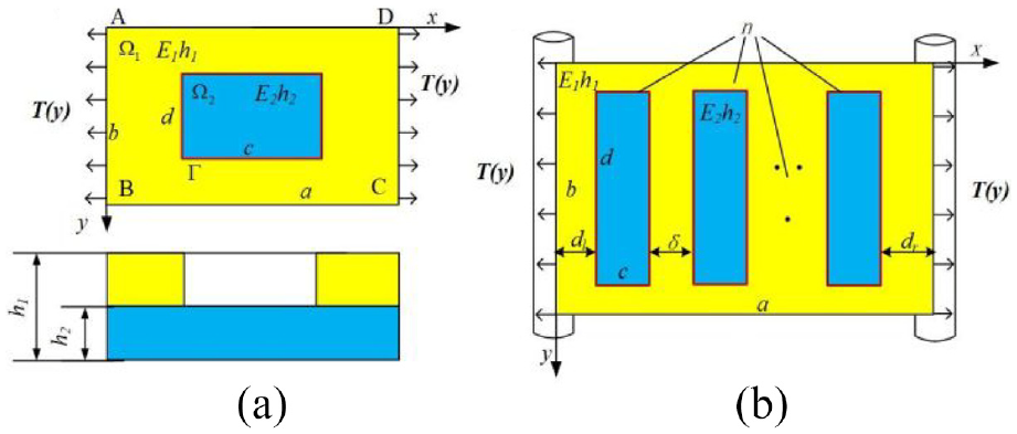
Non-uniform web between two rollers. The mechanical model of the web with (a) a single sub-region and (b) an array of sub-regions.
The commercial finite element analysis (FEA) software Abaqus is used to analyze the influences of various factors on the buckling strength of the web. Assume that the pretension used in the analysis is P0 and the obtained smallest positive eigenvalue is λcr, then the critical characteristic load can be obtained as Pcr = λcrP0. A dimensionless factor, buckling coefficient k, can be defined as equation (4), which represents the buckling strength of the web
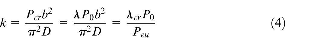
where
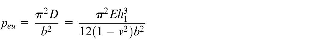
denotes the Euler buckling strength. The buckling coefficient k depends only on the dimensionless factors {α, β, γ, χ} and can be obtained by FEA method. Since the actual width
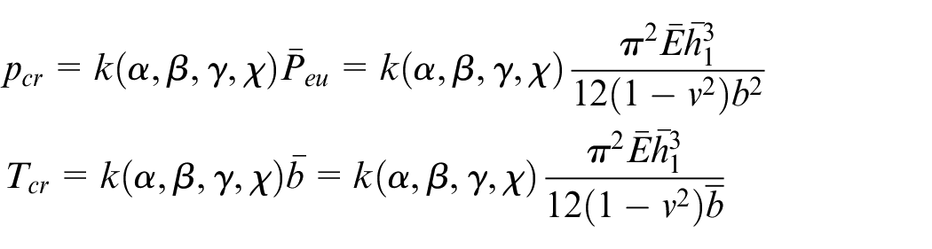
Through the analysis of numerical results, the effects of these four factors on the buckling coefficient are obtained. The parameters of the web used in the analysis are as follows: web width b = 400 mm, web thickness h1 = 0.01 mm, elastic modulus of the web and the sub-region E1 = E2 = 5GPa, web length–width ratio α = 1–10, length ratio of the sub-region β = 0.2–0.9, width ratio of the sub-region γ = 0.2–0.8 and thickness ratio of the sub-region χ = 0.1–0.8.
Figure 12 shows the relationship among the buckling coefficient, the web length–width ratio and the length ratio of the sub-region, with γ = 0.5 and χ = 0.5. Figure 12(a) indicates that k varies dramatically with α. With the augment of α, k decreases rapidly at first, then increases slowly and finally converges to a certain value. It can be seen from Figure 12(b) that there is a complex relationship between k and β. When α is small (e.g. α < 2.5), k decreases monotonically with the augment of β. For a relatively large α, the buckling coefficient fluctuates with the growth of β.
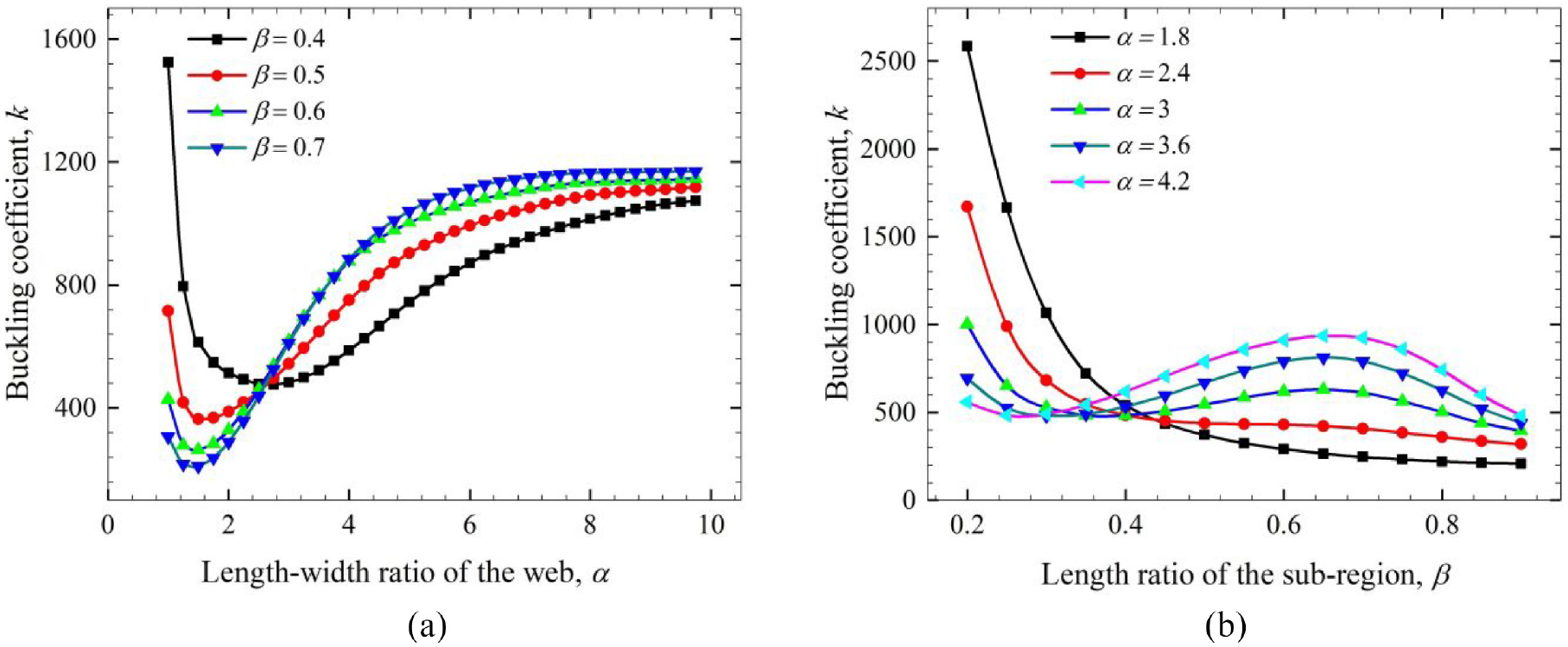
The relationship between the buckling coefficient k and (a) α and (b) β.
Figure 13 shows the relationship among the buckling coefficient, the width ratio of the sub-region and the thickness ratio of the sub-region. It can be seen from Figure 13(a) that the relation curve of k and γ is a bathtub curve for χ = 0.5. For γ = 0.5, the web is most nonhomogeneous along the width direction, which makes the stress distribution more non-uniform, and k reaches its minimal value. For β = 0.5, Figure 13(b) shows that χ has a large influence on k. With increase in χ, the web has larger bending stiff and more homogeneous cross section, which reduces the local compress stress and increases the buckling coefficient rapidly.
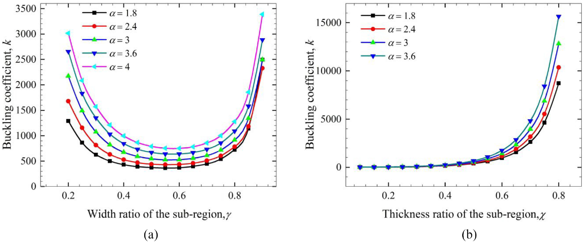
The relationship between the buckling coefficient k and (a) γ and (b) χ.
Another series of numerical analyses are carried out to obtain the buckling coefficient of the web during the transporting process. The parameters of the web used in the buckling coefficient by the FEA method shown in figure analysis are as follows: β = 0.2, γ = 0.8, χ = 0.5, h1 = 0.01 mm, b = 14. The buckling coefficient of webs with n = 4 uses the following: 400 mm, E1 = E2 = 5 GPa and δ/a = 0.05. The obtained buckling coefficient by the FEA method is shown in Figure 14. The buckling coefficient of webs with n = 4 uses the vertical axis in the right. It can be seen from Figure 14(a) that the buckling coefficient fluctuates significantly. The buckling coefficient reaches its minimum value, which means dl reaches its maximum, when φ = δ/(c + δ). The buckling coefficient reaches its maximum value when a new sub-region enters into the web zone completely and the rightmost sub-region leaves the web zone completely, that is, φ = c/(c + δ). The out-of-plane displacement of the web along the center of the web, that is, y = b/2, is shown in Figure 14(b). For φ = 0, the buckling waveform has a single peak which locates between the center of two sub-regions on the right side. For φ = 0.3, the waveform evolves as a form with double peaks. As the web transporting occurs, the waveform evolves back to the form of single peak at φ = 0.4, which locates in the center of two sub-regions on the left side. One must take the position of the sub-region into account when checking the buckling strength of the web. For example, the buckling coefficient varied about 15% for n = 4.
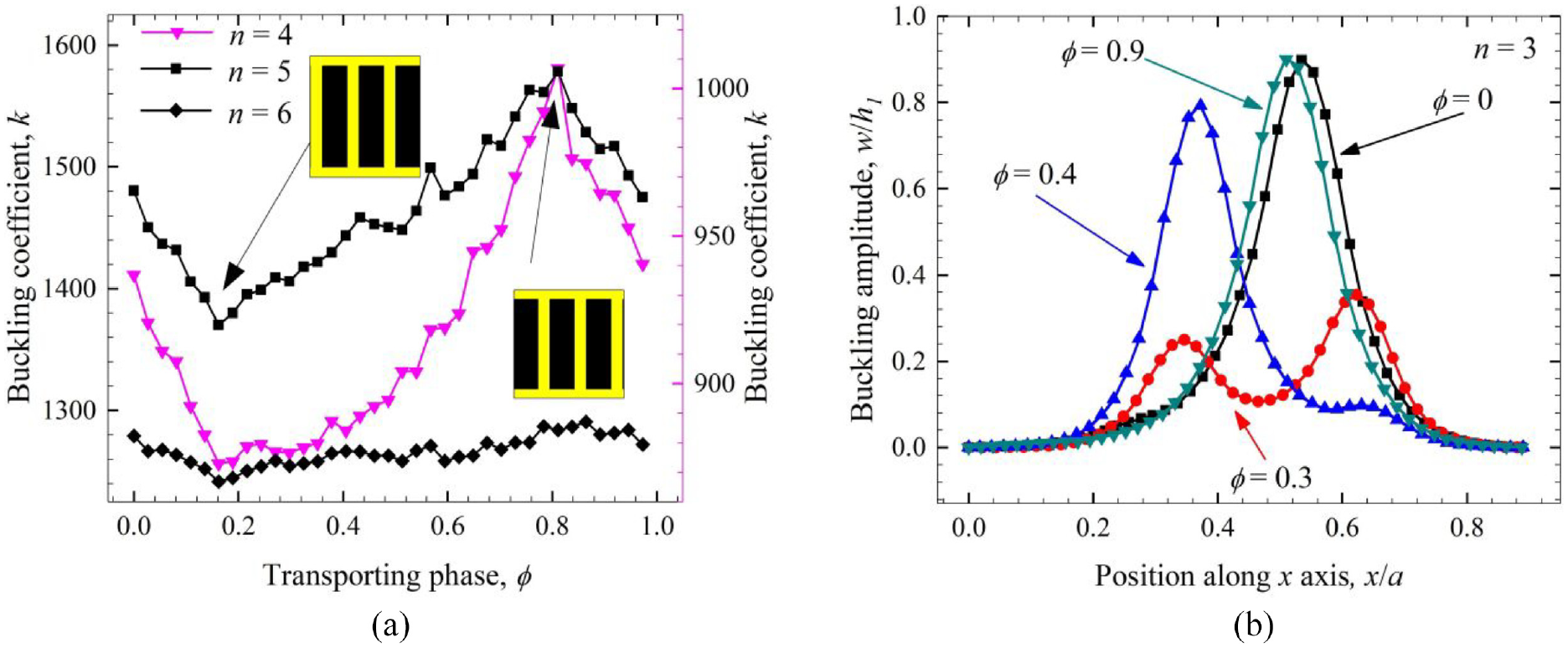
The variation of the buckling strength with web transporting: (a) the relationship between the buckling coefficient k and the transporting phase and (b) the variation of the waveform along y = b/2 during transporting process.
Conclusion
This article studies the GDL continuous overlaying technics and designs GDL continuous overlaying equipment. The GDL manipulator module accomplishes the picking and placing of GDL membranes efficiently. Hot-pressing module integrates GDL and CCM at a stable temperature field. The breakpoint die-cutting technics adopted in die-cutting module meets the requirements of detection and laying-off modules. The designed functional modules, including R2R lamination system, GDL manipulator module and hot-pressing module, are in good condition and meet the requirements of MEA lamination. The analysis of tension inhomogeneity and critical wrinkling guides the design of the R2R transporting system. The proposed R2R manufacturing system coordinates the discontinuous hot-pressing and die-cutting technics, continuous peeling technics and the GDL overlaying technics. These technics possess high extendibility and meet the needs of high-precision GDL processing.
Footnotes
Appendix 1
The three-dimensional model of GDL overlaying equipment is shown in Figure 15, which is divided into six modules. According to the layout direction, they are unwinding modules which come from the upstream technics, GDL manipulator module, hot-pressing module, die-cutting module, laying-off module and rewinding module. Snapshot of the real equipment is shown in Figure 16.
Declaration of conflicting interests
The author(s) declared no potential conflicts of interest with respect to the research, authorship, and/or publication of this article.
Funding
The author(s) disclosed receipt of the following financial support for the research, authorship, and/or publication of this article: This work was supported by the Program for Guangdong Key Areas Research and Development (2019B010924005) and the National Natural Science Foundation of China (51475195, 51635007).