
Abstract
To enable gigawatt-scale deployment of proton exchange membrane water electrolysers (PEMWEs), drastic reductions from current iridium loadings of 2–3 mgIr cm−2 to less than 0.4 mgIr cm−2 must occur due to iridium's high cost and scarcity. State-of-the-art systems use these high loadings to compensate for degradation experienced over prolonged operation. Thus, to attain low loadings while meeting commercial lifetime targets, factors such as ink formulation, MEA fabrication, catalyst layer–porous transport layer (CL–PTL) contact, and catalyst durability must be optimised. This review paper discusses the fundamentals of PEMWE technology and the modifications/improvements necessary for effective low iridium-loading design. Important milestones for future research include developing durable catalyst layers at low loadings, optimising the CL–PTL interface, and improving roll-to-roll production processes.
Keywords
Introduction
Countries worldwide have set targets to decarbonise their economies by 2050 or earlier. Hydrogen is an energy vector that can either be used as a fuel or as a chemical feedstock without generating any carbon dioxide. 1 Since hydrogen usage is clean, as long as the energy used to generate the hydrogen comes from clean power sources (e.g., solar, wind, geothermal, etc.), it can be termed ‘green hydrogen’. This versatility and zero-emission property of green hydrogen makes it a suitable candidate for decarbonising various sectors of the economy, especially sectors that have yet to see promising solutions – such as long-haul transportation and industrial manufacturing. 1 A proton exchange membrane water electrolyser (PEMWE) is a technology that uses electricity to split water into hydrogen and oxygen and is expected to make up 40% of the green hydrogen market. 2 However, the current deployment of PEMWEs is insignificant, accounting for less than a gigawatt (GW) of global capacity. However, to reach all national decarbonization targets, Clapp et al. 3 projects that PEMWEs will need to reach capacities of approximately 80 GW by 2030 and 580 GW by 2050. Several bottlenecks hinder PEMWE scale-up, including harnessing adequate renewable energy from the grid, scaling up the production of titanium cell components (bipolar plates and porous transport layers), and securing adequate amounts of catalyst material. Bernt et al. 4 recognise that these bottlenecks would behave differently at varying scales of PEMWE deployment and believe that the anode catalyst will be the limiting factor at the gigawatt scale.
Need for low iridium loadings
Iridium is the rarest element as only 0.000003 ppm exists in the Earth's crust (∼1000× rarer than gold 5 ) and is obtained as a secondary mining product of platinum-group-metals (PGM). 6 Another factor aggravating the difficulty in obtaining iridium is its geographical inaccessibility, as iridium sourcing is dominated by five countries: Canada, Russia, South Africa, the United States, and Zimbabwe. 7 The global iridium supply in 2021 was 8.3 ton/annum (annum = year), 8 meaning that all applications that utilise iridium are limited to this sparse amount. Furthermore, since iridium is obtained as a secondary mining product for PGMs, supply is not expected to increase without significant expansion of PGM mining. 3 The traditional iridium loading of a PEMWE ranges from a few hundred micrograms to a few milligrams per square centimeter. In large-scale applications greater than 10 megawatts, loadings of 2–3 mgIr cm−2 are currently used to ensure long-term durability.4,9,10 However, Clapp et al. 3 projects that to reach net zero emissions with green hydrogen, loading reductions to 0.10 mg cm−2 must occur by 2050, even in conjunction with significant iridium recycling.
Minke et al. 6 used modelling analysis to show that installation rates of just 8 GW/annum would correspond to an iridium demand of 5.36 ton/annum, constituting a staggering 65% of the global Ir supply in 2021. Furthermore, since other applications rely on iridium – such as spark plug manufacturing, ballast water treatment, process catalysts for acetic acid plants, copper foil manufacturing, and crystal making for the electronics industry – it is clear that there needs to be drastic loading reductions to enable substantial PEMWE scale-up. However, only a handful of studies have examined low-loading PEMWEs (Tables 1 to 3). Thus, much more rigorous research is required to design systems with reduced iridium content. Before discussing electrolyser design and future research milestones for the remainder of this paper, we shall first define what is considered a ‘low’ iridium loading since there is no consensus in the literature. After careful examination, it is observed that PEMWEs exhibit performance and durability changes near two loadings: 0.5 and 0.17 mgIr cm−2.11,12 Moreover, acknowledging the efforts of (i) the U.S. Department of Energy's (DOE) ‘H2NEW’ consortium – which sets 0.4 mgIr cm−2 as the 2026 loading target 13 – and (ii) the previously mentioned work by Clapp et al. 3 – which projects that loading reductions to 0.10 mg cm−2 could enable net zero emissions – we will define loadings from 0.4 to 0.1 mgIr cm−2 as ‘low’ loadings, and anything below 0.1 mgIr cm−2 as ‘ultra-low’ loadings.
Comparing PEMWE activity at low iridium loadings . Entries from top to bottom are sorted by decreasing activity, as assessed by taking the current density obtained at 1.8 V.
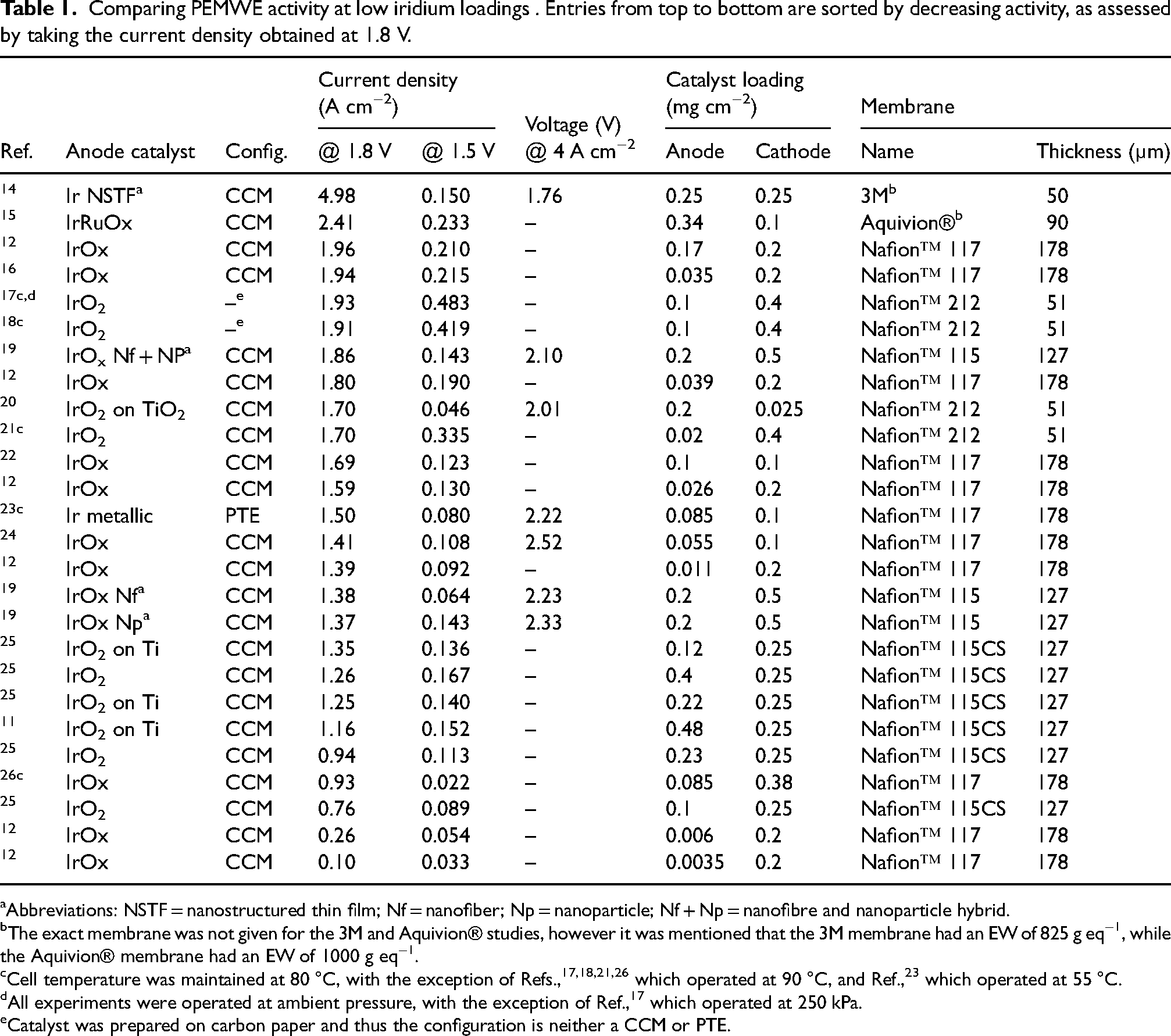
Abbreviations: NSTF = nanostructured thin film; Nf = nanofiber; Np = nanoparticle; Nf + Np = nanofibre and nanoparticle hybrid.
The exact membrane was not given for the 3M and Aquivion® studies, however it was mentioned that the 3M membrane had an EW of 825 g eq−1, while the Aquivion® membrane had an EW of 1000 g eq−1.
Cell temperature was maintained at 80 °C, with the exception of Refs.,17,18,21,26 which operated at 90 °C, and Ref., 23 which operated at 55 °C.
All experiments were operated at ambient pressure, with the exception of Ref., 17 which operated at 250 kPa.
Catalyst was prepared on carbon paper and thus the configuration is neither a CCM or PTE.
Comparing PEMWE degradation/durability at low iridium loadings. Entries are partitioned into three sections with respect to the reference current density used to determine the degradation rate. In each section, entries from top to bottom are sorted by decreasing durability.
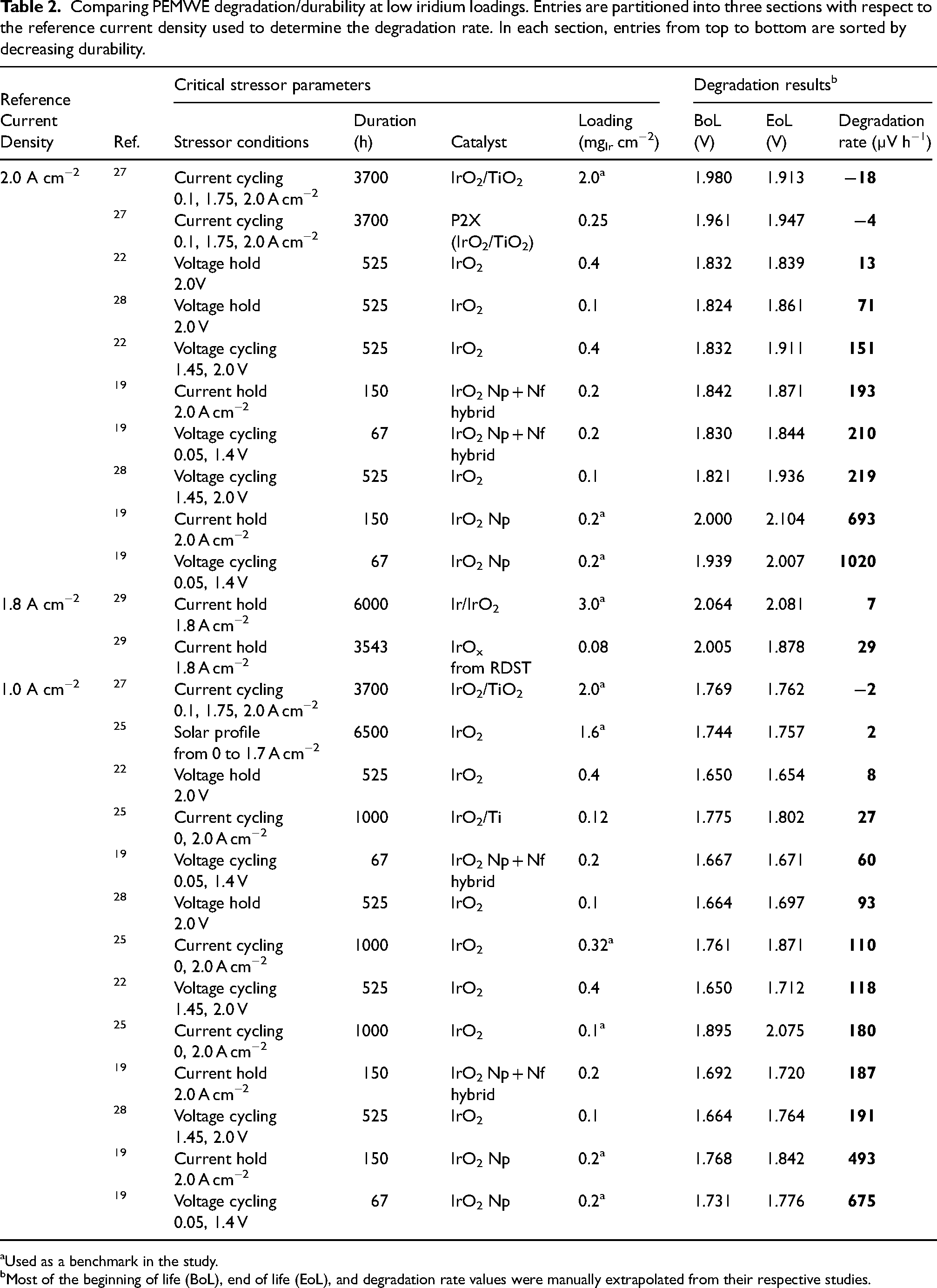
Used as a benchmark in the study.
Most of the beginning of life (BoL), end of life (EoL), and degradation rate values were manually extrapolated from their respective studies.
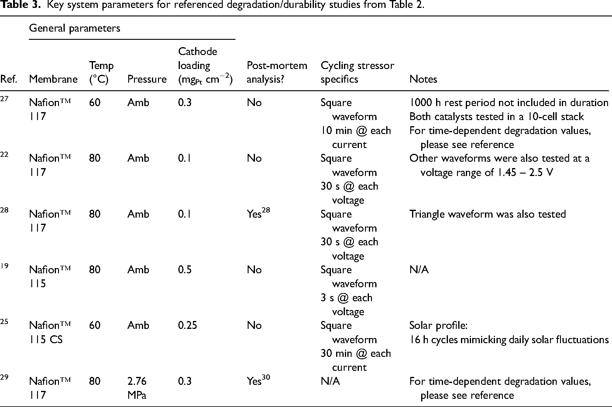
Key system parameters for referenced degradation/durability studies from Table 2.
MEA configurations and activity variations
Activity and durability trends obtained at high catalyst loadings do not translate directly to trends at low loadings. Catalyst activity will be discussed in this section, while durability will be discussed in the section ‘Catalyst layer degradation’. Table 1 summarizes the activity studies in the literature for low iridium-loading PEMWEs. The influence of different catalysts, supports, loadings, and operating conditions is mapped out to help determine optimal MEA design. The entries in the table are sorted by descending order of current density measured at 1.8 V as the metric (e.g., the entries at the top have the highest performance).
Two configurations are typically used for PEMWE MEAs: a catalyst-coated membrane (CCM) and a porous transport electrode (PTE). In a CCM, catalyst is deposited onto the membrane, while in a PTE, catalyst is deposited onto the porous transport layer (PTL). The difference in substrate, whether it is a membrane or a PTL, immensely impacts electrochemical performance. In a PTE, the CL may have greater electrochemical surface area than in a CCM due to the existing PTL pore structure, but the MEA may suffer from worse mass transport and ohmic resistance. In contrast, the CCM configuration benefits from uniform CL morphology but experiences membrane swelling and deformation at the CL–PTL interface. It is important to note that regardless of MEA configuration, operating under low catalyst loadings will introduce unique problems in addition to exacerbating existing issues.
CCMs with low catalyst loadings are most commonly fabricated via spray coating or blade coating. Numerous studies have demonstrated the ability to fine-tune iridium loadings in a CCM configuration via spray coating, from greater than 1 to below 0.05 mgIr cm−2.11,12,26,31 Rozain et al. 11 conducted a study of CLs fabricated by spray coating and observed that CL thickness increased with loading (0.5 to 6 µm from 0.1 to 2.2 mgIr cm−2). Moreover, the authors report a ‘threshold loading’ value of 0.5 mgIr cm−2, where PEMWE performance deteriorates upon further loading reductions. Taie et al. 12 reported this phenomenon as well, showing a threshold loading value of 0.17 mgIr cm−2. The variability in threshold values suggests that MEA optimisation is crucial at low and ultra-low loadings. Regarding the same study, a loading of 0.17 mgIr cm−2 outperformed the loading of 2.5 mgIr cm−2. When examining specific current (i.e. current normalised by mass of iridium), the loading of 0.011 mgIr cm−2 exhibited the highest value, which provides confidence that optimising the morphology of the CL can result in drastic loading reductions. An example of a highly optimised CL would be the nanostructured thin film (NSTF) CCM fabricated by 3M. With a loading of 0.25 mgIr cm−2, this CCM enabled current densities of 19 A cm−2 at ≈2.85 V. 14 The use of this MEA resulted in a reduction of approximately 250 mV at 4 A cm−2 compared to other MEAs operating in similar conditions (Table 1). Not only was this CCM highly optimised, but its design was also novel at the time. Some recent examples of novel CCM design include i) a ‘hierarchical’ platinum-iridium bilayer with low tortuosity fabricated via doctor blade coating (Peng et al. 32 ) and ii) an interlayer design where isolated iridium islands are bridged together with iridium nanofibres – at a loading of 0.2 mgIr cm−2, this catalyst outperformed the catalyst with no interlayer at a loading of 1.2 mgIr cm−2 (Hegge et al. 19 ).
Support materials and catalyst blends have also been investigated to curtail catalyst loading. Rozain et al. 11 fabricated CCMs using IrO2 nanoparticles supported by metallic titanium to show that the support increased thickness and volumetric charge (indicative of greater electrochemical surface area) under the same iridium loading. They also found that the supported IrO2 at 0.12 mgIr cm−2 exhibited similar performance to unsupported IrO2 at 0.4 mgIr cm−2 for lower current densities and similar performance to unsupported IrO2 at 0.71 mgIr cm−2 for higher current densities. Improvements mainly originated from lower ohmic and kinetic losses from the supports, stemming from enhanced electronic conductivity and improved catalyst dispersion, respectively. When iridium loadings of the supported catalyst increased, higher mass transport overpotentials were observed, likely germinated by a thicker catalyst structure. Other supports for iridium have been investigated in the literature – such as NbO2, 33 and TiN, 34 and antimony-doped SnO2 35 – but further investigations at an MEA scale are required to assess their viability.
Studies of low-loading PTEs are rarely seen as they show a tendency to have higher loadings due to two difficulties arising from fabrication: (i) the length scale of PTL pores requires a sufficient amount of deposited catalyst ink to ensure uniformity and connectivity of the CL (PTLs without MPLs have surface pores >20 µm), and (ii) the hydrophilicity of the PTL causes ink intrusion into its pores, resulting in wasted catalyst and (iii) blade coating methods generally require inks with higher solid ratios (>>5 wt% 36 ), resulting in higher loadings (solid ratio is defined as the mass of all solid components – i.e. the catalyst and ionomer – divided by total mass).37–40 PTEs at low catalyst loadings were fabricated by Van Pham et al. 41 using TiO2 supports, where the performance of these catalysts at 0.4 mgIr cm−2 was comparable to that of unsupported catalysts at 1.2 mgIr cm−2. Recently, novel types of PTEs fabricated with innovative coating techniques have been explored by several groups and show great performance under low loadings – reaching 7 A cm−2 at 2 V with 0.16 mgIr cm−2.42–44
CL morphology and structural properties – such as pore size distribution, porosity, and thickness – are greatly influenced by anode catalyst loadings, as shown in Figure 1. For CCM CLs, higher loadings are thicker and possess larger agglomerates, while lower loadings are denser. For PTEs, higher loadings are thicker and denser, while lower loadings are more uniform. While physical characterisation analyses on catalysts at an MEA scale – such as FIB-SEM and nano X-ray computed tomography – have been widely employed for fuel cell applications, it has largely been overlooked for PEMWEs, especially at low loadings. In conjunction with traditional electrochemical techniques (such as polarisation curves and EIS), applying these characterisation techniques to obtain structural information could provide invaluable insight into catalyst optimisation.
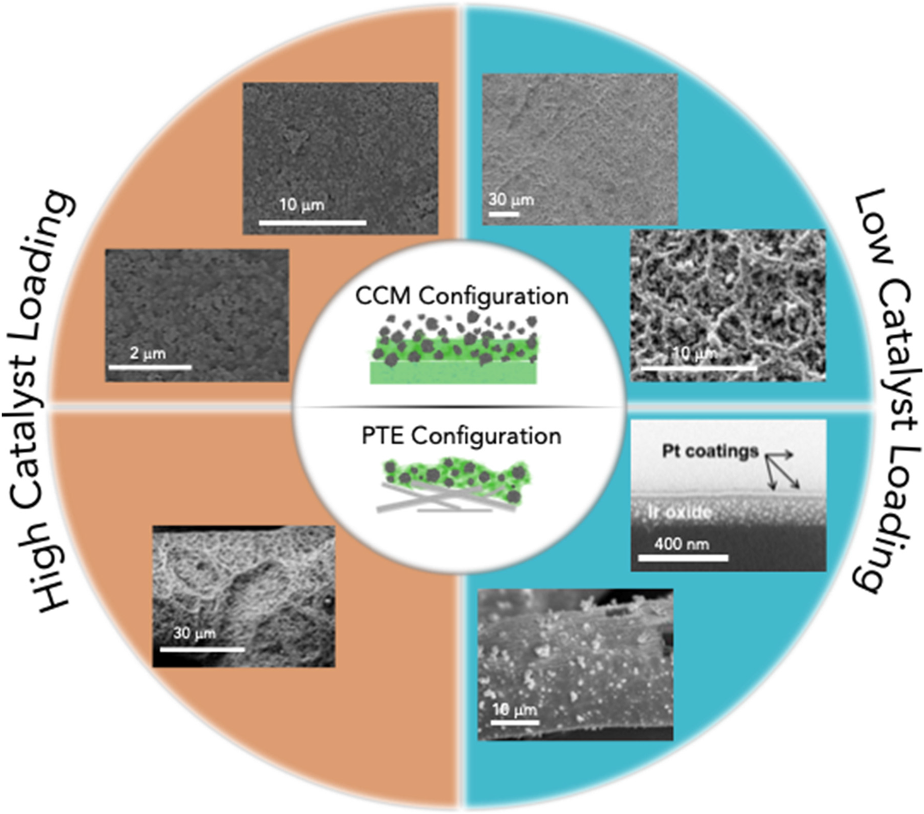
Morphologies of catalyst layers in CCM and PTE configurations at high and low catalyst loadings.
MEA fabrication methods
Methods for fabricating MEAs (for CCM or PTE configurations) and their advantages/disadvantages will be discussed in this section. Spray coating and blade coating are the most traditionally used MEA fabrication methods, and an overview of the two processes is shown in Figure 2. Spray coating involves using a spray device to deposit fine droplets of catalyst ink onto the substrate to form a catalyst layer. In contrast, blade coating involves dropping a bulk amount of ink onto the substrate and then using a tool (i.e. blade, rod or cylinder) to sweep across the surface and disperse the ink to form a catalyst layer. After examining these two processes, considerations regarding improving roll-to-roll manufacturing processes to meet growing PEMWE production will be discussed.
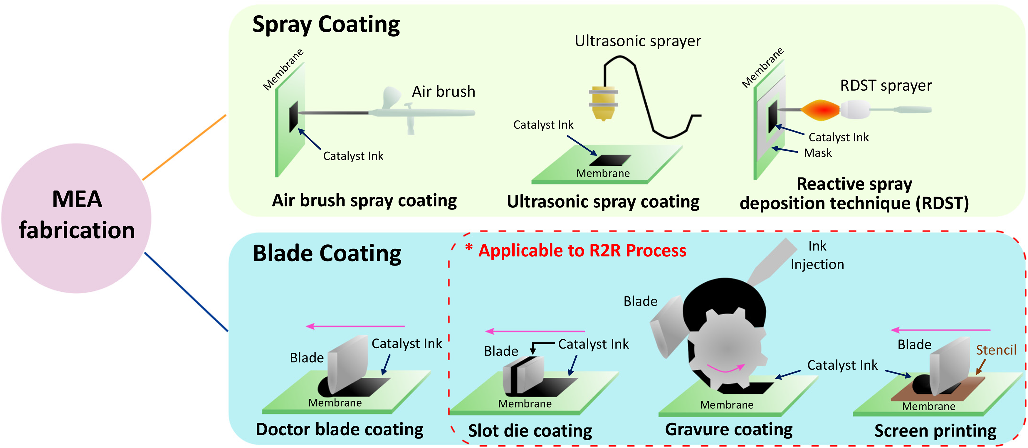
Breakdown of different MEA fabrication techniques. Spray coating includes airbrush spray coating, ultrasonic spray coating, and reactive spray deposition technique. Blade coating includes doctor blade/knife/rod/bar coating, slot die coating, gravure coating, and screen printing. Substrate is shown as a membrane for ease of visualization but can also be a PTL.
Spray coating is a method where catalyst ink is deposited onto a substrate using a spray device. This device may be a simple airbrush or be more sophisticated, such as an ultrasonic-based atomisation coater, where ultrasonic vibrations are used to atomise and disperse the catalyst ink into finer droplets. Spray coating devices vaporise catalyst ink and deposit it onto a substrate (that is, a PTL for a PTE or a membrane for a CCM). Generally, spray coating provides low MEA throughput and is therefore intended for small-scale applications, but its high repeatability and precision control over the CL structure make it appropriate for research. 31 This section will cover three widely used spray coating techniques: (i) airbrush, (ii) ultrasonic-based and (iii) reactive spray dispersion technology. Airbrushing is the most traditional spraying technique and uses inert gas or air to atomise the catalyst ink. Introducing compressed gas into the stream of ink at the nozzle breaks down the ink into droplets, which are then sprayed onto the substrate. 45 The relative ease of airbrushing makes it suitable for conducting screening tests with many catalysts inks. Ultrasonic-based spray coating grants more uniformity to the catalyst structure compared to airbrushing by applying harmonic vibrations to pulverise the ink into finer droplets. For instance, a frequency of 120 kHz has been found to form droplet sizes of about 20 µm, 45 allowing for uniform and well-dispersed CLs. Since dilute inks are used for spray-coating methods (<<1 wt% 36 solid content, which is defined as the mass of catalyst and ionomer divided by total mass), longer deposition times are expected – especially for higher loadings – raising concerns about catalyst particles settling in the catalyst ink. In the case of an ultrasonic-based spray coater, the catalyst ink becomes atomised again at the tip and is hence less of a concern, but clogging of the nozzle tip may still occur.31,46,47 Moreover, ultrasonic-based coating systems are typically built-in to a computer numerical control (CNC) machine, enabling coating of larger areas 45 compared to airbrushing, as well as better scalability overall. A potential way to scale up airbrushing and ultrasonic-based spray coating is installing multiple nozzle heads for simultaneous deposition. The last spray coating technique discussed in this section is the reactive spray deposition technique (RSDT), which operates under a different mechanism than the aforementioned techniques. RSDT combines at least five processes of CL fabrication (e.g., catalyst synthesis, ink formulation, ink mixing, ink deposition, decal transfer, etc.) into a single process. 48 The ability to produce aerosols of narrow size distribution is of critical importance in the RSDT process, where an ultra-fine mist is generated from an iridium precursor solution and then combusted to create nanoparticles for catalyst deposition. The PFSA ionomer is then deposited afterwards. Yu et al.29,30 conducted a series of low-loading CCM (at 0.08 mgIr cm−2) degradation studies under industry-relevant conditions (active area = 86 cm2; differential pressure = 400 psi) using RSDT and found that the technique enhanced both performance and durability, although a higher degradation rate still resulted when compared to the baseline 3 mgIr cm−2 PTE fabricated via airburshing. 29 Interestingly, RSDT is capable of using any soluble precursor, regardless of the vapour pressure, allowing for inexpensive precursors to be used for cost reduction.49–52
Blade coating is a method for fabricating MEAs with relatively low investment costs. This process entails dropping or injecting a certain volume of ink onto a substrate and then having a blade sweep forward over the ink (Figure 2). Although either the blade or substrate may be moved to form the CL, moving the blade is favoured because the membrane is typically heated under vacuum conditions (to prohibit swelling), making it more challenging to move. While the general method is called blade coating, one can offer more specificity to the naming depending on the coating tool being used: doctor blade coating (when a doctor blade is used), knife coating (when a knife is used), bar coating (when a cylindrical bar is used), or rod coating (when a wound wire is used). There exist two factors that impact the coating thickness: (i) ink rheology and (ii) the meniscus between the tool and the substrate. 53 Certain coating parameters – such as gap height, coating speed, and tool geometry – may also be tuned to control coating properties. Similarly, ink parameters – such as solvent composition, ionomer to catalyst (I/C) ratio, and solid-content – may be tuned to control rheology and agglomeration, which will ultimately impact the CL microstructure. 54 One note is that blade coating has often resulted in higher loadings than spray coating (see Refs.55–57) due to the higher solid content (>5 wt% 36 ) traditionally used in the inks.
To meet the volume and cost targets of growing PEMWE production, further developments in the roll-to-roll (R2R) manufacturing process are crucial. The R2R process is where a flexible substrate is unwound, coated with a continuous liquid film, dried and then re-wound, which dramatically curtails material and labour costs at industrial scales.36,58 Slot die coating, gravure coating, and screen printing are blade coating techniques that use a continuous ink supply and thus are suitable for R2R production. Slot die coating uses two independent metal components to form a slit where the catalyst ink gets injected. The slot die head has a fixed gap above the substrate, which can be tuned to control CL thickness. The ink injection rate can also be tuned to control CL morphology. Gravure coating uses a cylinder with engraved patterns filled with ink that is rolled over the substrate to create a CL. 53 Similarly, screen printing uses a blade to sweep ink over a stencil to coat the substrate. For all three of these techniques, the catalyst can be directly coated onto a membrane; however, swelling of the membrane becomes an issue due to the longer interaction times between ink and substrate in a R2R process. 59 Although the method of decal transfer – a technique where the coating is first made onto a sacrificial substrate (typically PTFE) and then transferred onto a membrane – prevents swelling as it is a dry process, it imposes an additional step to the manufacturing process. Furthermore, concerns exist about the CL's pore structure collapsing during the process of transfer from sacrificial substrate to membrane.
Considerable knowledge on crafting effective anode CLs has been accrued in recent years, but technical know-how on fabricating high-quality, low-loading anode CLs (such as elucidating optimal ink and coating parameters) still remains to be established. A few challenges include achieving uniformity, tuning structural properties (e.g., porosity, tortuosity, pore size distribution, etc.), scaling up manufacturing, and ensuring durability. For instance, many of the high-performing low-loading CLs in the literature are fabricated via spray coating12,22,32 as it grants greater precision control compared to blade coating. However, spray coating is more impractical for larger-scale manufacturing. Thus, further research must be pursued in fabricating effective low-loading CLs with blade coating, such as deciphering how ink properties impact CL quality when dilute inks are used (since these methods have traditionally used inks with higher solid-content). When aiming to reduce loadings, ink viscosity can be decreased (via changing the processing time, solvents used, etc.), the ink can be diluted, or the height of the coating tool can be lowered. Lastly, innovative approaches for MEA fabrication – such as the ionomer-free PTEs demonstrated by Lee et al. 23 – could also guide efforts to achieve efficient large-scale manufacturing.
Ink fabrication
The preliminary step in fabricating CLs is to create the catalyst ink, which is a composition of catalyst and ionomer dispersed in a solvent mixture of alcohol and water. The structure of the CL, which manages reactant and product transport, as well as ionic and electronic transport, can be tuned by altering ink properties. However, the link between liquid ink properties and solid CL structure has largely been overlooked in the literature, especially at low loadings. This section discusses this ink–CL relationship and presents future research efforts required for ink optimisation.
Only a few studies have discussed the effect of ink properties on anode CL structure, even at high loadings. Deriving knowledge acquired from fuel cell platinum on carbon (Pt/C) catalyst inks, some of the crucial parameters of ink formulation include solid-content,60,61 aggregation,54,62 and ionomer conformation.63–65 Due to the rigorous amount of knowledge required to study and characterise inks comprehensively, most of the current work on PEMWEs have simply correlated cell performance with a few broad ink parameters: solid-content, ionomer to catalyst ratio, and solvent composition. Bernt et al. 66 investigated the impact of ionomer content in the anode CL and demonstrated that low content leads to insufficient ionic conductivity, while high content leads to mass transport and electronic conductivity losses. Similarly, Alia et al.31,67 found that ionomer content and the morphology of the catalyst-ionomer interface signficantly affect kinetic performance. For mass transport performance, the primary properties are aggregate size, porosity, and pore size distribution. These values can be manipulated by altering the solvent composition; for instance, Kumano et al. 68 obtained smaller aggregate sizes when introducing ethanol to the solvent mixture (as opposed to using only water and n-propanol).
In addition to examining how ink properties can affect the CL structure, one must also carefully tailor the ink formulation to the MEA fabrication method being used, as some ink rheologies may not be suitable for certain methods. However, studies on ink characteristics and their impact on different MEA fabrication techniques are currently lacking and thus must be further explored. For example, spray coating – which uses dilute ink – experiences challenges in throughput and CL structure control, while blade coating – which uses viscous ink – experiences challenges in CL uniformity and loading control. A better understanding of the interplay between ink properties and coating techniques will help overcome these problems and enable effective large-scale MEA fabrication.
Under ultra-low loadings, the CL's conductivity (ionic and electronic) and mass transport properties12,69 are especially crucial. The CL is significantly thinner at these loadings, which further emphasises the importance of uniformity, as disconnected catalyst islands can drastically reduce electronic conductivity. Furthermore, if large spaces exist where catalyst particles are absent, the ionomer will selectively fill those areas and cause heterogeneity in ionomer distribution, exacerbating mass transport issues. Therefore, finding ink rheologies that grant uniform coatings will be necessary to achieve durable and active ultra-low-loading CLs. To aid these efforts, more smaller-scale characterisation should be done, using techniques such as nano-CT 70 or FIB-SEM. 32 Nano-CT in conjunction with pore network modelling (PNM) is a method proposed by Lee et al. 70 that can help in understanding how different ink compositions affect structural properties in the CL (e.g., how varying the I/C ratio would impact pore size distribution). FIB-SEM analysis on a blade coated Pt–Ir CL conducted by Peng et al. suggests that tortuosity can significantly affect mass transport, demonstrating that nanostructural properties of the CL (in this case, the nanostructure was a ‘nano-pattern’) can significantly impact performance. 32 Employing such characterisation techniques will elucidate the relationship between catalyst ink properties and CL structure, providing potentially critical information in fabricating active and durable low- and ultralow-oading MEAs.
Catalyst layer–porous transport layer interface design
CLs with ultralow iridium loadings without stable supports have severe in-plane electrical conductivity issues stemming from the presence of isolated catalyst islands. PTLs are adjacent to the CL on the anode side and are responsible for reactant/product transport, electronic conduction to the current collector, mechanical support 60 for the catalyst layer, and heat removal,71,72. PTLs in PEMWEs are typically made from coated or uncoated titanium (Ti), as opposed to carbon-based materials in PEM fuel cell diffusion layers. Although carbon is still the material of choice for the cathode diffusion layer in PEMWEs, the high oxidative potentials and low pH on the anode make carbon extremely susceptible to corrosion/oxidation and hence cannot be used. Ti shows adequate corrosion resistance and has excellent electronic conductivity, making it a suitable PTL material. However, Ti PTLs have challenges of high material costs and difficulties/complexities in manufacturing at large scales. 73 Although PTLs currently encompass a major part of total system cost, there is significant cost reduction potential with alternative materials such as stainless steel. However, these materials must overcome issues of corrosion resistance and cation poisoning (where contaminants leach into the water stream, interact with the PFSA ionomer in the MEA and cause CL and membrane degradation). 74 One of the solutions to mitigate these issues is to use durable precious or non-precious metal coatings on the PTL. Platinum is the most widely commercially used coating material and is known to considerably improve corrosion resistance and, as a result, durability.10,75 Non-precious metal coatings also exist but are still in the developmental phase. For example, Stiber et al. 76 used a stainless-steel mesh coated with Nb/Ti for corrosion resistance and successfully showed 1000 h of operation with minimal degradation. In summary, research in alternative materials and metal coatings can significantly imrpove cost and durability. Aside from these material considerations, another aspect worth optimising is the catalyst layer–porous transport layer (CL–PTL) interface.
The CL–PTL interface is dictated by the surface structures of the CL and PTL and is perhaps the most important interface in PEMWEs, influencing catalyst utilisation, voltage efficiency, and durability. The complex nature of the two-phase flow between liquid water moving towards and gaseous oxygen moving away from the CL makes the interface critical to ensure efficient mass transport. CL–PTL interfacial contact also influences electronic conductivity since in-plane electronic transport usually happens on the PTL surface at lower catalyst loadings due to the greater inhomogeneity of the CL.20,77 Furthermore, when less conductive catalyst supports are used, interfacial contact becomes even more criticial as in-plane electronic conductivity issues of the CL are exacerbated.20,77 Lastly, even proton conductivity can be affected by CL-PTL interfacial properties as localised proton pathways could be influenced by the PTL microstructure, even with homogeneous coverage of the proton conducting media (i.e. the ionomer and water) at the interface. Several experimental studies have examined the effect of PTL morphology on PEMWE operation.78,79 Figure 3a shows scanning electron microscopy (SEM) images of several PTL architectures. The most common morphologies in commercial systems include fibre and sintered Ti PTLs, and novel morphologies include expanded titanium mesh PTLs, titanium PTLs with micropores, and unitised designs of bipolar plates with sintered titanium PTLs.80–82 Although each morphology has different pros and cons, the final choice will ultimately depend on cost, high-volume manufacturability, and the desired catalyst loading. It is also important to note that as loadings become progressively lower, the CL–PTL interface becomes increasingly critical to ensure effective operation.
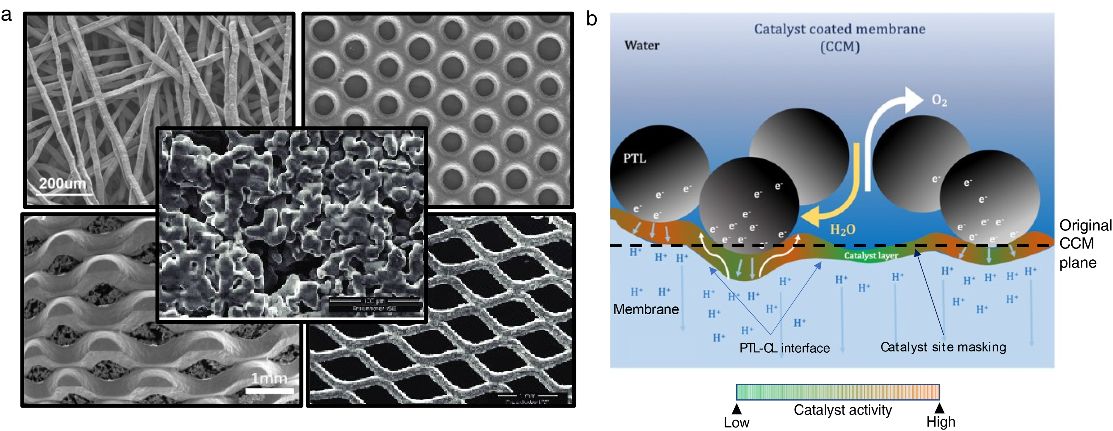
(a) SEM micrographs of various PTL structures including (in a clockwise direction starting from the upper left) titanium fibre, titanium with micropores, expanded titanium mesh, porous sintered titanium layer on a titanium mesh, centre: sintered titanium powder. Reproduced with permission from Refs.72,79,80 (b) Schematic of the CL–PTL interface showing degrees of catalyst utilisation (based on the nature of PTL contact) and proton and electron transport pathways . Colour scheme: increasing oxygen evolution reaction (OER) activity from green to orange. Catalyst site masking effects can be caused by localised accumulation of gaseous oxygen, preventing water flow to catalyst sites.
In addition to influencing ohmic and mass transport, the CL–PTL interface also affects kinetic performance. Figure 3b illustrates the nature of varying degrees of catalyst activity for the OER at the CL–PTL interface, with orange representing greater activity. The catalyst utilisation depends on the nature of the interfacial contact and the density of the contact points. In a series of two studies, Schuler et al.83,84 experimentally investigated the effect of PTL fibre diameters and porosities on PEMWE performance. In the first study, 83 the effect of surface roughness was correlated with interfacial contact. They formulated the specific interfacial contact area (RICA) based on the degree of membrane plastic deformation due to PTL surface roughness and contact pressure. The surface roughness of the fibre PTLs was seen to increase significantly with the increase in fibre diameter, which ultimately reduces RICA. In the second study, 84 RICA was shown to influence catalyst utilisation, ohmic resistance, and membrane heat transfer. To gain insight into improving interfacial contact, Lee et al.69,85 used stochastic and PNM approaches to optimise the diameter of the titanium powder used to make sintered PTLs. They evaluated reactant transport with PNMs and quantified CL–PTL contact using PTL surface roughness. Their results showed a tradeoff between reactant transport and contact resistance – denser and less porous PTLs reduce contact resistance at the expense of more sluggish reactant transport. Lastly, Lopata et al. 26 studied the effect of various PTLs at low catalyst loadings. They found that PTL properties affect performance by impacting the in-plane conductivity and permeability of the CL. In short, the evidence is abundant to show that emphasis must be placed on the CL–PTL interface when designing low-loading PEMWEs.
Microscopy and modelling efforts can also be used to garner additional insight. Leonard et al. 86 first used X-ray CT to investigate interfacial contact with both CCMs and PTEs. Kulkarni et al. 87 used the same technique to quantify the triple phase contact area (TPCA) – the geometric common area between PTL, CL and membrane – for fibre and sintered titanium PTLs. TPCA is used as a measure of catalyst utilization as the OER can only occur at this interface. It was found that sintered PTLs exhibit higher TPCAs than fibre PTLs due to their lower porosity and denser surface structure, which allows for increased contact with the CL. Higher interfacial contact reduces kinetic and ohmic overpotential due to improved catalyst utilisation and reduced contact resistance, respectively. The kinetic overpotential benefit has been reported as decreased Tafel slopes while ohmic overpotential benefit has been reported as decreased high-frequency resistance.20,88–91 Furthermore, it was found that the TPCA also strongly influences mass transport as corroborated by X-ray radiography and lattice Boltzmann method (LBM) simulations. 92
Metal coatings on the PTL can be utilised to improve corrosion resistance and electronic conductivity at the surface. Platinum-group metals such as platinum, iridium, and gold have been studied and are typically the materials of choice.93–95 Using coated PTLs significantly increases system lifetime by slowing down degradation when compared to uncoated PTLs, where surface oxide growth results in increasing electronic contact resistances. 75 However, long-term stability and durability depend on the coating material, coating method (electroplating, sputtering, physical vapour deposition (PVD)), and PEMWE operating conditions. Degradation mechanisms, such as metal dissolution and delamination, have been reported in the literature during extended high current density operation (>2 A cm−2 for 2000 h). 94 Some studies report iridium being a superior coating when compared to platinum due to the improved stability and higher conductivity of its oxides.55,96 Iridium coatings have also been recently reported to reduce CL restructuring and ionomer loss at the interface during extended operation (4000 h), 97 as well as providing OER activity. 97 These advantages have been argued to justify using additional expensive iridium metal as a coating. Other surface modification approaches include using mixed metal oxide (MMO) coatings 98 and titanium hydride subsurface layers via acid etching 99 to improve corrosion resistance. Titanium hydride does not affect the electronic conductivity of the PTL, but does significantly resist the formation of titanium oxide, thus reducing passivation. 100 Advances in PTL coatings will ultimately enhance CL–PTL interfacial properties and improve overall electrolyser activity and durability.
Necessity of the microporous layer
A common consensus among the PEMWE community is the necessity of developing graded PTLs with pore sizes decreasing towards the CL (discussed in detail by Yuan et al. 101 ) or incorporating a microporous layer (MPL) – a layer with fine pore and particle sizes – into the PTL. MPLs can help maximise interfacial contact, especially at low and ultra-low catalyst loadings, and enable the usage of thinner membranes as they reduce membrane deflection (i.e., the deformation of the membrane into PTL pores). MPLs have been widely utilised in fuel cells to reduce catalyst loadings and improve durability and water management. While similar benefits can result, MPL incorporation in PEMWEs has additional challenges including adapting to a modified purpose (electrolyser PTLs experience liquid and gas flow instead of just gas flow in fuel cells), overcoming material limitations, and developing large-scale manufacturing methods.
One of the first attempts at creating titanium-based MPLs for electrolysers was by Lettenmeier et al. 102 by vacuum plasma spraying (VPS) fine titanium powder on sintered titanium filters. Their results showed improved electrolyser performance and reduced internal cell resistance (−20 mΩ cm−2) compared to the MPL-free sample. Kang et al. 78 fabricated MPLs with micro-scale titanium particles (∼5 μm) and nano-scale titanium particles (30–50 nm) using a low-temperature air spraying method. They found that microparticle MPLs offered significantly improved performance over nanoparticle MPLs (1.707 V◊1.687 V at 2.0 A cm−2) due to increased pore access for water and oxygen transport. Although their MPLs were hydrophobic in nature, which is detrimental for electrolyser PTLs, their PTL architecture (pictured at the top right in Figure 3(a)) provided sufficient water access at the interface. Schuler et al. 103 studied the effect of MPLs on catalyst utilisation. Using MPLs made from thermally sintered ttanium particles with varying sizes, the authors found that smaller MPL particle sizes lead to higher interfacial contact and that catalyst utilisation increased by a factor of 2.2–2.8 with MPL usage.
There is ample evidence to advocate for incorporating MPLs, and future research avenues exist to optimise their impact on PEMWE performance, such as tuning morphology and hydrophilicity. However, MPL studies on low-loading PEMWEs are scarce, and their overall effect on activity and durability needs to be thoroughly investigated. At lower loadings, the CL especially suffers from insufficient electronic conductivity, and thus MPLs could be critical in combatting this issue. As we consider scale-up, the final downselection of MPLs will not only depend on performance enhancements, but also on MPL durability, methods for in-line quality control, and high-volume manufacturing.
Catalyst layer degradation
One of the utmost concerns regarding low-loading MEAs is their accelerated degradation since lifetime cannot be compromised in commercial applications – even at the expense of cost-effective loadings. Thus, understanding and improving system durability is imperative to PEMWE scale-up. When comparing catalyst measurements in MEAs with measurements in aquous electrolytes, durability predictions can differ by several orders of magnitude, 104 prompting concerns about the relevance of the aqueous environment for stability measurements.105,106 A thorough review of the stability of iridium in aqueous electrolytes (for the OER) is available in the literature. 107 Given the nature of this review, we narrow our scope exclusively to studies focusing on the degradation of low iridium-loading MEAs.
The methods used to examine degradation of low-loading MEAs in the literature can generally be broken down into two strategies: (i) electrochemical characterisation to track and differentiate between kinetic, ohmic and transport overpotentials, and (ii) pre- and post-mortem characterisation (e.g. cross-sectional SEM, scanning tunnelling electron microscopy (STEM), X-ray energy dispersive spectroscopy (XEDS), and ICP-MS) to better understand CL shrinkage and iridium sinks.22,28,104,108,109 Several CL architectures have been studied that utilise various MEA fabrication methods and catalysts types: traditional spray coating, 22 ultrasonic spray coating, 28 RSDT, 29 NSTFs, 14 IrOx nanofibre interlayers, 19 and IrO2 and IrO(OH)x supported on TiO2, 27 with durability tests ranging from 67 h to over 4500 h.
Table 2 summarises the degradation studies done on low-loading MEAs in the literature, with Table 3 listing important cell parameters of the studies included. Tracking the overpotential,, defined as the increase in cell potential above thermodynamic oxygen evolution (1.23 V at standard conditions), is a routinely employed metric for monitoring changes in MEA activity induced by degradation. Tracking overpotential rather than current densitiy is generally preferred as the potential defines the thermodynamic stability of the CL 110 and standardises comparison across MEAs with different operating conditions (e.g., temperature, pressure, etc.). 22 Overall cell overpotential consists of kinetic, ohmic, mass transport, and other contributions. CL degradation will result in higher kinetic overpotential (as less overall surface area of the catalyst will be available for the OER) and changes in these overpotentials can be examined through Tafel analysis. 109 The ohmic or mass transport overpotential can also increase due to the cation effect, where dissolved iridium cations move towards the cathodeand block the transport of protons in the membrane and reaction sites at the cathode. Furthermore, as the CL thins, further increases in high-frequency resistance can be observed due to the worsening of in-plane electronic conductivity, but this effect will be heavily influenced by the nature of the CL–PTL interface and the presence/absence of a MPL. For stability (constant load) and durability (load cycling) testing, the degradation rate is expressed as the change in cell voltage over time (µV⋅h−1),, where a higher positive value indicates a greater degradation rate. Althoughthis rate is dependent on test duration (as the degradation rate may evolve with time28,109) and the reference current density (i.e., the current density at which potentials are measured to calculate the degradation rate) – which makes comparison between degradation rates from different studies inherently challenging – we nonetheless adopt this metric given its prevalence in the literature.
Other dissolution-centric metrics like the S-number (which quantifies the ratio of evolved oxygen to dissolved catalyst) 111 and the activity-stability factor 112 carry significant insights and have also been employed, albeit primarily for aqueous systems and sparingly for MEAs as the quantification of dissolved catalyst by using an ICP-MS instrument (which is relatively expensive) is required.
Cell potential degradation
The 2026 target and ultimate target for average degradation rate listed by the United States DOE are 2.3 and 2.0 µV⋅h−1, respectively. 13 When performing assessments for MEA degradation, some form of load cycling should be administered given that electrolysers will need to operate according to renewable energy load profiles for technoeconomic feasibility. 113 Table 2 sumarizes the results for low iridium-loading PEMWE degradation studies in the literature. As cell potential and degradation rate are functions of current density, all degradation values will be listed with respect to a reference current density. Degradation rates measured at 2 A cm-2 ranged from 13 to 693 µV⋅h−119,22 for the constant current and constant potential stability tests, which are orders of magnitude higher than the DOE's targets. It should also be noted that some studies found negative degradation rates; the implications of such values will be discussed in the following paragraph.
Compared to constant loads, dynamic cycling tends to produce larger increases in cell potential over time, with degradation rates ranging from 27 to 1020 µV⋅h−1 (when measured at 2 A cm-2).19,25 As shown in Table 2, while a constant potential hold at 2.0 V for 525 h resulted in an EoL cell potential of 1.839 V, square wave cycling between 1.45 and 2.0 V led to an EoL cell potential of 1.911 V. 22 Larger increases in cell potential were also observed for the sawtooth-up, sawtooth-down, triangle-wave, model wind , and model solar cycling profiles, with EoL cell potentials of 2.014, 1.973, 1.944, 1.784 and 1.776 V, respectively, despite the cycling profiles having a lower average potential (1.863, 1.863, 1.725, 1.700 and 1.700 V, respectively) than the hold profile (2.0 V).22,28 These findings are particularly interesting given that exposure to higher upper cell potential limits led to more rapid degradation. Moreover cell potential increases were amplified when iridium loadings were reduced from 0.4 to 0.1 mgIr⋅cm−2, as shown in Figure 4. This result was assumed to be a consequence of the greater iridium loadings (and CL thicknesses) acting as buffers for the delayed onset of degradation. The observation of increased CL degradation rates for low-loading MEAs was also reflected in most studies that compared low-loading and baseline-loading CLs, as shown in Table 2. Additionally, cycling from 0 to 1.7 V, which mimics PEMWE shutdown and reductive hydrogen crossover conditions, resulted in increased degradation rates compared to a sequential current and potential hold modelling a mitigated PEMWE operation profile at 1 A⋅cm−2 and 1.3 V, respectively. 104 Interestingly, when the cycling and constant hold protocols were performed in sequence, regardless of order, the combined increases in overpotential were almost equivalent. We must note, though, that this study featured iridium loadings of 2.0 mgIr⋅cm−2 (and hence wasn't included in the table) and relatively short degradation tests ranging from ≈17 to 34 h. While the findings have yet to be reproduced for low iridium-loading MEAs, we nonetheless believe they are relevant. Lastly, decreasing cell potentials with time have also been reported with dynamic cycling (Table 2), but this does not necessarily mean the CL was not degrading, as a simultaneous decrease in HFR via membrane thinning can mask increases in kinetic overpotentials. 27 Cells can sometimes takes long timesto properly condition, therefore prolonged testing on the order of thousands of hours is needed to understand the true durability of MEAs.
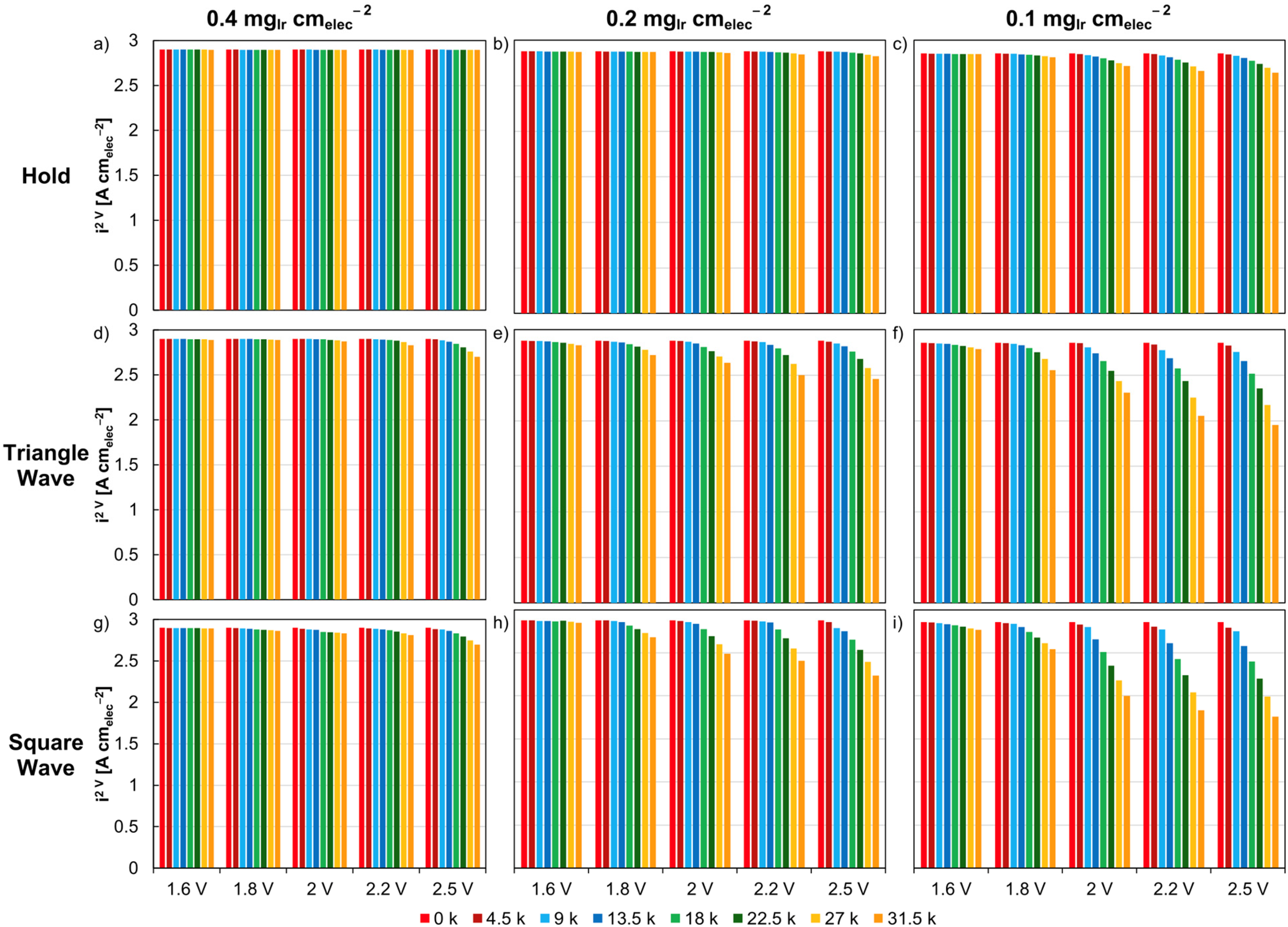
Steady-state potential holds for MEAs with loadings of (a) 0.4, (b) 0.2, (c) 0.1 mgIr⋅cm−2. Potential-based triangle-wave cycling for MEAs with loadings of (d) 0.4, (e) 0.2, (f) 0.1 mgIr⋅cm−2. Potential-based square-wave cycling for MEAs with loadings of (g) 0.4, (h) 0.2, (i) 0.1 mgIr⋅cm−2. Potential holds were completed at 1.6, 1.8, 2.0, 2.2 and 2.5 V. Triangle and square-wave cycling was conducted at a lower potential of 1.45 V and upper potentials of 1.6, 1.8, 2.0, 2.2 and 2.5 V. Adapted from Ref. 22
Post-mortem characterisation
Post-mortem characterisation is increasingly being used to correlate degradation rate observations with physical changes in the MEA, with emphasis placed on imaging the CL and mapping the displacement of iridium (and occasionally platinum). All instances of such characterisation have observed iridium losses from the anode CL via a combination of elemental quantification (STEM-XEDS) and visual observations of CL thinning (cross-sectional SEM).22,28,30,104 It has been deduced that iridium can be removed from the anode CL through several routes: galvanic corrosion with uncoated PTLs, 108 dissolution into the anode and cathode water lines, 104 and dissolution into the membrane. 30 Despite the extensive focus on iridium dissolution in aqueous electrolytes, one study calculated that only 7% of the iridium losses originate from iridium dissolution into the water lines (based on MEA results with coupled ICP-MS and post-mortem STEM-XEDS and cross-sectional SEM), with the rest of the lost iridium redepositing either in the membrane or cathode CL. 104 However, the amount of dissolution in the study was small, with iridium losses amounting to only around 0.04% of the initial 2.0 mgIr⋅cm−2 loading due to the shorttime of degradation imposed on the MEA(∼30 h). Although high loadings and short testing times were used, the results of this study are nonetheless a relevant addition to the sparse literature featuring electrochemical and post-mortem MEA characterisation. Another study with orders of magnitude lower loadings and longer testing times (0.08 mgIr⋅cm−2 and 4500 h) also observed similar findings with the following: (i) iridium migration into the membrane and iridium presence on the cathode CL, (ii) platinum migration into the membrane (similar to what has been observed for Pt/C cathodes in PEM fuel cells 114 ), and (iii) Pt/Ir bimetallic precipitates, Pt deposition in the anode CL, and Ir and Pt signals throughout the PEM, as shown below in Figure 5.28,30 A 70% loss of initial iridium loading was noted, however, which may be explained given the longer degradation time. Furthermore, they found that cathode deposition was the most significant contributor to anode catalyst loss, with 60% of the lost iridium ending up on the cathode. 30 A study with dynamic potential cycling also observed iridium migration into the membrane and a decrease in anode CL–membrane interfacial contact, although interestingly no plating of iridium in the cathode CL was observed. 28 However, the authors note that this may be due to shorter degradation times and different experimental conditions. In a similar study by the same authors, 22 decreases in anode CL thickness, porosity, and pore size were observed after degradation, pointing to a reduction of CL surface area.
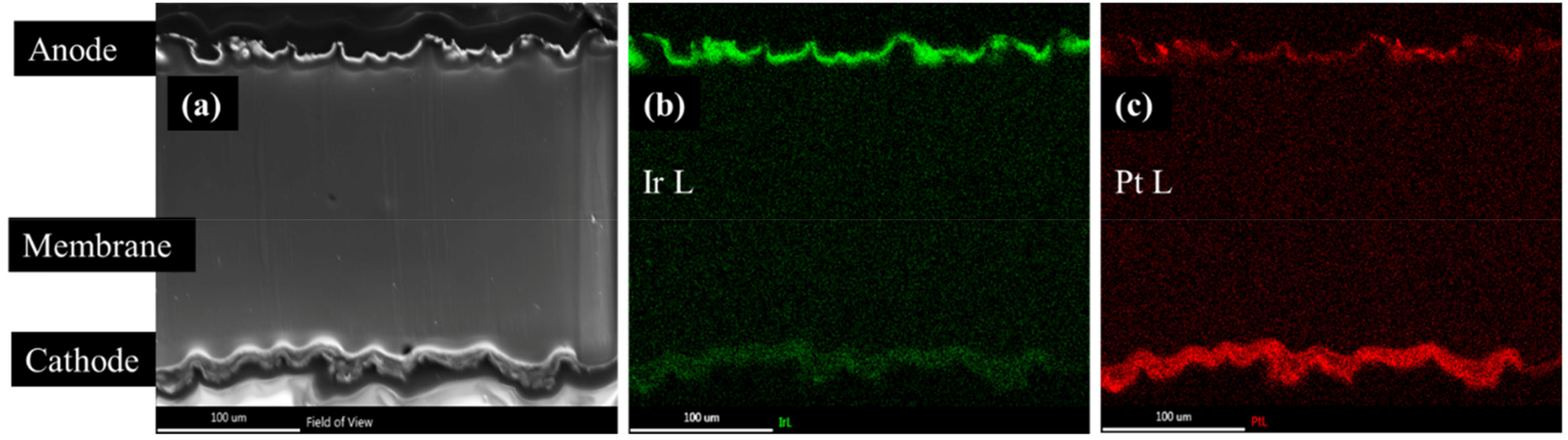
STEM-XEDS mapping of an MEA region denoted by (a). Iridium and platinum mapping are shown in (b) and (c), respectively. Adapted from Ref. 30
Outlook
Clear evidence of anode CL degradation has been shown through overpotential monitoring and iridium loss from the CL, with the membrane, cathode CL, and water lines as iridium sinks. To guide future efforts, we note the following: (i) While the HER indeed has a much lower overpotential than the OER, the effects of cathode CL degradation are often assumed to be negligible and consequently neglected (aside from a few studies28,30) despite the scarcity of systematic studies on these effects. Moreover, there is a lack of studies examining the effects of unintended platinum in the anode CL, which can impact CL conductivity. (ii) It is unclear to what extent iridium dissolves and redeposits within the anode CL via Ostwald ripening, which may reduce CL surface area. Similarly, the conditions that induce iridium redeposition on the cathode are unclear given mixed results in the literature.28,30,104 Further studies will be beneficial to determine what operating conditions and cell characteristics lead to iridium redeposition at the cathode side. (iii) Given the current focus on increasing in-plane electronic conductivity for low-loading CL design, the extent to which in-plane (or even through-plane) electronic conductivity is maintained – and the corresponding effect on iridium utilisation – after degradation is unknown. Currently, studies addressing these three concerns and (more generally) how iridium losses translate to increases in cell overpotential are scarce. More research is needed to provide definitive conclusions on CL degradation to aid future low iridium-loading MEA design. On a broader scale, since degradation rate is a highly prevalent metric for examining durability, efforts should be made to standardise test duration and the reference current density to make comparisons between studies more reliable.
Conclusion
Large-scale deployment of PEMWEs will utlimately require iridium loading reductions from 2–3 mgIr⋅cm−2 to 0.1 mgIr⋅cm-2. 3 Spray coating and blade coating are the most common MEA fabrication methods, with blade coating being better suited for roll-to-roll manufacturing. Effective ink formulation will depend on the coating method being used, and ink properties will play a critical role in dictating CL performance, especially at low and ultra-low loadings. Solvent composition, ionomer content, catalyst properties, and solid-content must be carefully tuned to achieve desirable conductivity and mass transport properties. The use of catalyst supports can increase catalyst dispersion and CL thickness, allowing for improved in-plane electronic conductivity and catalyst utilization. Finally, a PTL with favourable morphological properties and an integrated MPL will be a prerequisite for active and durable PEMWE design. Regarding durability, dynamic load cycling is an effective way to induce expedited degradation while also mimicking realistic PEMWE operating conditions. Pre- and post-mortem characterisation techniques – such as STEM-XEDS, cross-sectional SEM, and ICP-MS – can be used to better understand CL degradation and iridium dissolution. Since durability research on low-loading PEMWEs is sparse, more research must be done before fully informed efforts can be made in designing more durable catalysts.
In summary, this article has discussed the fundamentals of ink formulation, MEA fabrication, CL–PTL interfacial contact, and catalyst durability, with a stern focus kept on low-loading PEMWE design. Future milestones were also discussed, with the most notable being developing durable catalyst layers at low loadings, optimising the CL–PTL interface, and improving roll-to-roll manufacturing processes. As we face the dire challenges of reducing greenhouse gas emissions, PEMWEs will be essential in decarbonisation efforts. With the remarkable research trajectory and governmental funding that has occurred thus far, much optimism exists for PEMWEs to become a reliable and cost-effective solution to combat climate change in the imminent future.
Footnotes
Declaration of conflicting interests
The authors declared no potential conflicts of interest with respect to the research, authorship and/or publication of this article.
Funding
The authors disclosed receipt of the following financial support for the research, authorship and/or publication of this article: The authors acknowledge the Department of Energy – Office of Energy Efficiency and Renewable Energy – Hydrogen and Fuel Cell Technologies Office (DOE-EERE-FCTO) and the H2 from the Next-generation of Electrolyzers of Water (H2NEW) consortium for funding under Contract Number DE-AC02-05CH11231.