
Abstract
Depositing large components (>10 kg) in titanium, aluminium, steel and other metals is possible using Wire + Arc Additive Manufacturing. This technology adopts arc welding tools and wire as feedstock for additive manufacturing purposes. High deposition rates, low material and equipment costs, and good structural integrity make Wire+Arc Additive Manufacturing a suitable candidate for replacing the current method of manufacturing from solid billets or large forgings, especially with regards to low and medium complexity parts. A variety of components have been successfully manufactured with this process, including Ti–6Al–4V spars and landing gear assemblies, aluminium wing ribs, steel wind tunnel models and cones. Strategies on how to manage residual stress, improve mechanical properties and eliminate defects such as porosity are suggested. Finally, the benefits of non-destructive testing, online monitoring and in situ machining are discussed.
Keywords
Introduction
Additive manufacturing (AM) is a technology that promises to reduce part cost by reducing material wastage and time to market. 1 Furthermore, AM can also enable an increase in design freedom, which potentially results in weight saving as well as facilitating the manufacture of complex assemblies formerly made of many subcomponents. 2
A basic AM system consists of a combination of a motion system, heat source and feedstock. Owing to its intrinsic characteristics, each process is naturally suitable for certain applications. For instance, selective laser melting delivers net shape components with high resolution; however, similarly to electron beam melting, deposition rates are relatively low, and part size is limited by the enclosed working envelope. 3 Consequently, this class of processes is best suited to small components with high complexity. The main business drivers for their adoption are freedom of design, customisation and possibly reduced time to market. 1 The benefit associated with the reduction in material waste is limited; the mass of the components is already low to begin with. While the possibility of topologically optimising certain components is important, there is a growing requirement for larger reductions in material waste, for the following reasons. First, with the increasing usage of carbon fibre reinforced polymers, aircraft designers are forced to shift from aluminium to titanium, the former being electrochemically incompatible with carbon. 4 Second, with the current and forecast aircraft market expansion rate, the demand for titanium parts is increasing accordingly. 5 Third, titanium is an expensive material to source and machine. 6 Therefore, in the aerospace industry, there is a pressing need for the development of a process that could replace the current method of manufacturing large structures such as cruciforms, stiffened panels, wing ribs, etc., which are machined from billets or large forgings, with unsustainable buy/fly (BTF) ratios. This metric is the ratio of the mass of the initial workpiece to the one of the finished product; in the aerospace sector, values of 10 or even 20 are not unusual. 7
Wire+Arc AM (WAAM)
The combination of an electric arc as heat source and wire as feedstock is referred to as WAAM and has been investigated for AM purposes since the 1990s, 8 although the first patent was filed in 1925. 9 WAAM hardware currently uses standard, off the shelf welding equipment: welding power source, torches and wire feeding systems. Motion can be provided either by robotic systems (Fig. 1a) or computer numerical controlled gantries. Figure 1b shows a friction stir welding machine, which has been equipped with a metal inert gas (MIG) power source. The retrofitted machine features a bed, which is 5 m × 3 m in size.
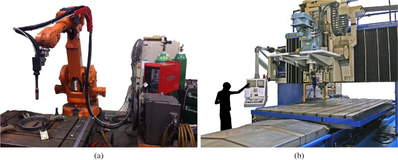
a six-axis ABB welding robot; b deposition system retrofitted onto former friction stir welding machineMotion systems options for WAAM
Processes
Whenever possible, MIG 10 is the process of choice: the wire is the consumable electrode, and its coaxiality with the welding torch results in easier tool path. In particular, Fronius cold metal transfer (CMT) is a modified MIG variant, which relies on controlled dip transfer mode mechanism; this is supposed to deliver beads with excellent quality, lower thermal heat input and nearly without spatter. 11 While meeting these expectations when depositing materials such as aluminium and steel, unfortunately, with titanium, this process is affected by arc wandering, 12 which results in increased surface roughness. Consequently, tungsten inert gas, 13 or plasma arc welding, 14 is currently used for titanium deposition. These processes, however, rely on external wire feeding; for deposition consistency, the wire must be fed always from the same direction, which requires rotation of the torch, thus complicating robot programming. 14
Example parts
WAAM's layer height is normally in the range of 1–2 mm, resulting in a surface roughness (the waviness) of roughly 500 μm for single track deposits. 14 Consequently, WAAM cannot be considered a net shape process, and machining is required to finish the part. It follows that WAAM is better suited for low to medium complexity and medium to large scale parts.
Figure 2a shows a 1.2 m Ti–6Al–4V wing spar made for BAE Systems, 15 which was deposited in a flexible enclosure using plasma arc welding with a seven-axis robotic system. The part features straight and curved features, all perpendicular to the substrate, and T junctions. Two parts were built simultaneously by alternating deposition on either sides of a sacrificial substrate (Fig. 2b); the reason for this will be discussed later. The deposition rate was 0.8 kg/h with a BTF ratio of 1.2.
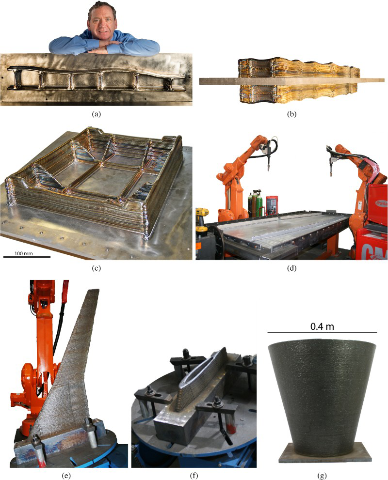
a 1.2Ti–6Al–4V wing spar built for BAE Systems, top view (courtesy BAE Systems; 15 process: PAWWAAM); b side view (please note two-component built back to back; courtesy of BAE Systems 15 ); c 24 kg Ti–6Al–4V external landing gear assembly (process: PAWWAAM); d 2.5 aluminium wing spar (process: Fronius CMT Advanced 11 WAAM); e high strength steel wing model for wind tunnel testing (process: Fronius CMT 11 WAAM); f particular of hollow structure; g mild steel truncated cone (process: Fronius CMT 11 WAAM)Recent parts built by WAAM
Figure 2c shows a 24 kg Ti–6Al–4V external landing gear assembly. The part was also built at 0.8 kg/h on either side of the plane, which gave the largest symmetry (see ‘Residual stress’ under ‘Challenges’), sharing the same set-up of the spar of Fig. 2a and b. This part features T junctions, crossings, perpendicular and slightly tilted walls. With a BTF ratio of 1.2, WAAM enabled material savings in excess of 220 kg.
Figure 2d shows a 2.5 m aluminium wing rib, which is currently machined from solid with a BTF ratio of 37–670 kg are required for a finished product of 18 kg. A part rotator was also employed, and the rib feet were added by WAAM at 1.1 kg/h using Fronius CMT Advanced 11 on either side of the plane of symmetry, which coincided with the substrate. Owing to the size of the part, two robots were depositing material simultaneously. No enclosure was required. The final part has a stiffening web in between the rib feet, which was not deposited but will be machined out of the thicker substrate, which is accommodating it. This results in a BTF ratio for WAAM of 12, sufficient to enable material savings of roughly 500 kg per part.
Figure 2e shows a 0.8 m wing for wind tunnel testing built in partnership with Aircraft Research Association. Specifically, Aircraft Research Association is aiming at reducing the time between the release of design surfaces to the gathering of data in the wind tunnel. The deposition process was Fronius CMT 11 with a deposition rate of 3.5 kg/h. The wing features a hollow structure up until its midpoint (Fig. 2f) and will be machined to an accuracy of 0.05 mm.
Finally, Fig. 2g shows a steel profiled cone also built by Fronius CMT 11 at 2.6 kg/h. The deposition parameters produced a wall thickness of 2.5 mm; against a target of 2 mm, the BTF ratio was 1.25. Further to this, lead time can be cut potentially from 6 months to just a few hours.
Benefits
Capital cost
A six-axis robot (£50k), a power source and torch (£30k) and the clamping tooling (£10k) constitute the basic WAAM hardware, for a total of £90k. This system is suitable for deposition of steel and aluminium. In case of titanium, given the additional requirement for an inert atmosphere, an enclosure might be necessary (an extra £20k).
Open architecture
The end user can potentially combine any brand of power source and manipulator retaining total control over the hardware. This is managed by software, WAAMsoft, which controls the process and can be adapted to the specific equipment available in the manufacturing cell. Furthermore, the user retains the freedom to change any deposition parameter; the software suggests the deposition parameters on a feature basis, but the user can customise them if required.
Part size
Materials such as aluminium or steel do not have a stringent requirement for gas shielding; consequently, the maximum part size is determined uniquely by the reach capability of the manipulator. For materials that require shielding such as titanium, the size is limited by the inner envelope of the chamber or tent used to create the inert atmosphere.
Deposition rate
Deposition rates are sufficiently high to make the deposition of large scale parts achievable in reasonable times. With rates ranging from 1 kg/h to 4 kg/h for aluminium and steel respectively, most parts can be manufactured within one working day. Higher deposition rates can be achieved (e.g. 10 kg/h), but this then compromises the fidelity of the part. For instance, at 10 kg/h, the BTF ratio can be as high as 10 for the final deposited part, 16 which is effectively a preform, thus requiring significant machining as well as the deposition of much more material, making the process less attractive from an economic point of view. Keeping the deposition rate at medium levels (e.g. 1 kg/h for titanium and aluminium, and 3 kg/h for steel) ensures that a BTF ratio of < 1.5 is always achieved, maximising the cost saving.
Material cost and utilisation
Welding wire is a cheap form of feedstock. Steel is priced between £2 /kg and £15 /kg (depending upon wire diameter and alloy composition), aluminium between £6 /kg and £100 /kg (depending upon wire diameter and alloy composition) and Ti–6Al–4V between £100 /kg and £250 /kg (depending upon wire diameter and alloy composition). Furthermore, wire avoids many of the challenges associated with powders such as control of particle size or distribution, which affect process performance. Finally, at the point of deposition, the wire is entirely molten and becomes part of the final structure, and the likelihood of contamination is low compared with powder.
Materials
Ti–6Al–4V
Additively manufactured Ti–6Al–4V displays superior damage tolerance properties; in particular, high cycle fatigue can be one order of magnitude better than that of the wrought alloy. 13 However, Ti–6Al–4V is affected by strong anisotropy of both tensile strength and elongation. Owing to its solidification characteristics, AM components display columnar prior β grains 13 and a highly textured microstructure. 17 This results in higher strength in the direction parallel to that of the layers; vice versa, the elongation is superior in the perpendicular direction.
To overcome this problem, rolling may be used to plastically deform the deposit by applying a vertical load.18,19 A schematic of the equipment used to perform high pressure interpass rolling is shown in Fig. 3. The process refines the prior β grain microstructure as well as the α phase laths, ultimately resulting in isotropic mechanical properties.20,21 Rolling strains the component in both the normal and transverse directions; 19 the energy stored in the crystallographic system combined with the heat provided upon deposition of a new layers triggers recrystallisation. The refined material has a yield strength of 994 MPa, an ultimate tensile strength of 1078 MPa and an elongation of 13;20,21 these values are all better than the wrought alloy (950 MPa, 1034 MPa and 12 respectively) 13 and are not dependent upon solidification conditions; rather, they rely on the mechanical processing of the part during deposition. 21
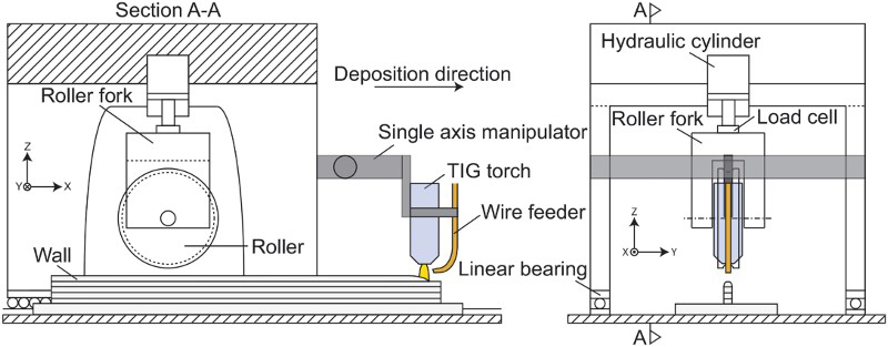
Schematic diagram of rolling and welding equipment
Aluminium
Additively manufactured aluminium is affected by porosity. 22 It has been shown that, using a combination of good quality welding wires and certain synergic operating modes, porosity can be eliminated.23,22 In particular, Fronius CMT in its pulsed advanced 11 variant is particularly beneficial, thanks to lower heat input, which results in finer equiaxed grains and effective oxide cleaning of wire and substrate. 22
Besides Ti–6Al–4V and aluminium; steel, invar, brass, copper and nickel have been successfully deposited. With each material, the focus is on guaranteeing mechanical properties and eliminating defects such as porosity.
Challenges
Residual stress
The significant heat input associated with arc sources leads to high residual stress, manifest in distortion once the component is unclamped. 24 Residual stresses are associated with the shrinkage during cooling and are largest along the direction of deposition. 25 Currently, the following methods are employed to mitigate this issue.
Symmetrical building
A plane of symmetry is identified within the volume of the component; the initial substrate will coincide with this plane. Using a part rotator, the deposition of the layers is alternated on the two sides of the substrate; the layer deposited on one side produces stresses, which balance those produced on the other side. Whenever a plane of symmetry cannot be identified, the substrate will be aligned to the plane, which separates the two resulting volumes in the most balanced way. The part shown in Fig. 2c was built with this strategy.
One additional benefit of this approach is the more effective heat management; while a new layer is deposited, the previous one cools down. The disadvantage is that parts could require redesign; for example, a C section component will need to be redesigned into an I section one.
Back to back building
When the starting plate is not part of the component, or when a redesign of the part is not possible, components can be built on either side of the same substrate, which, in this case, is sacrificial. The part shown in Fig. 2b was built in this way. This approach does not require redesign and is also characterised by improved heat management; however, two distinct components are made in each step. Consequently, this strategy is recommended when two symmetrical parts are needed, such as when manufacturing wing spars. The parts are subsequently heat treated to relax the residual stresses, before separation.
Optimising part orientation
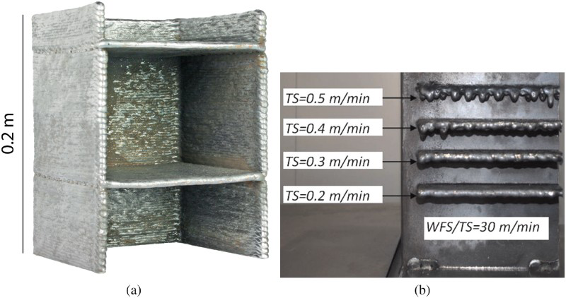
The deposition of shorter layers leads to lower residual stress and distortion; consequently, in preproduction, the part can be orientated in such a way that the slicing produces the shortest tool paths. For instance,the wing spar shown in Fig. 2b could be deposited vertically, i.e. with the planes of the layers perpendicular to its longest dimension. Figure 4a shows a feasibility study in steel in which the same spar was deposited with this approach. It was possible to produce horizontal features without the need for support structures by relying on the surface tension of the molten metal. An appropriate selection of the deposition parameters is even more crucial when depositing out of position. In particular, the travel speed (TS) has the largest effect on deposits quality. 26 Figure 4b shows that, for a given wire feed speed/TS ratio of 30 (keeping the WFS/TS ratio constant ensures that both the amount of material per unit of length and the heat input are kept constant), the lowest TS of 0.2 m/min resulted in the best deposit; the quality progressively deteriorated for increasing TSs, and finally, deposits were unacceptable for a TS of 0.5 m/min. 26
However, while desirable from a residual stress point of view, reorientation of the part also resulted in a much larger number of starts/stops, which is often impractical in a real industrial manufacturing scenario.
High pressure interpass rolling
Besides the microstructural benefits (discussed in the ‘Materials’ section), the strain introduced by a rolling pass results also in mitigation of the residual stress. 27 Figure 5c shows the effect of roller type and rolling load on the longitudinal residual stress distribution of G3Si1/ER70S-6 WAAM linear components. While the unrolled specimen showed a peak stress of 600 MPa, that of the components rolled at 50 kN was 300 MPa. The slotted roller, which provided additional side restraints and therefore resulted in a larger strain in the longitudinal direction, reduced the peak stress even further to 250 MPa. Moreover, in the region at the top of the wall, wherein the as deposited specimens residual stresses are moderately tensile, rolling resulted in compressive stresses.
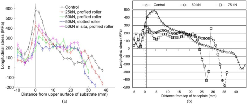
Figure 5b shows the residual stress distribution of rolled and unrolled linear Ti–6Al–4V components. The final stress status was very similar to their steel equivalent: rolling reduced the peak stress at the interface between the component and the substrate, and introduced larger compressive stresses at the top of the deposits. 25
Unfortunately, rolling alone has not proved to be capable of eliminating distortion completely due to unrestrained shrinkage and deformation, 28 and other strategies are being investigated.
Non-destructive testing (NDT) and online monitoring (OLM)
With the view of qualifying WAAM for applications such as structural components for civil aviation, NDT and OLM must be developed. With regards to NDT, shape, porosity levels and grain size must be measured during deposition. The shape measurement is necessary to ensure that each layer is deposited consistent to the tool path, which is generated after slicing of the computer aided design (CAD) drawing. Furthermore, it monitors whether any unexpected distortion due to residual stress occurs.
Porosity might occur due to poor quality wire, as well as its mishandling. 13 Identifying pores as soon as they appear allows their in-process elimination, for instance using in-process machining (see following section).
Finally, within the Engineering and Physical Sciences Research Council funded HiDepAM project, spatially resolved acoustic spectroscopy 29 is being investigated to assess the grain refinement produced by high pressure rolling, in situ. Spatially resolved acoustic spectroscopy is a non-contact and non-destructive technique, which relies on laser generated and detected surface acoustic waves, determining the local acoustic velocity and thus mapping the microstructure of polycrystalline materials.
With regards to OLM, arc parameters such as voltage and current, as well as WFS are recorded by a digital logger. From a quality management point of view, monitoring such data allows root cause analysis should a problem arise during deposition. A system for monitoring arc and part temperature is currently being developed. The former is useful to identify deviation from controlled processing parameters, the latter to ensure that each new layer is deposited within consistent thermal conditions. Changes in these result in unexpected variations of the geometry of the deposit bead, which reduces accuracy with regards to both the width of the deposited track and the height of the layer. The latter, in particular, is key in terms of reproducing the CAD slicing accurately.
Integrated machining
WAAM is a near net shape process, which requires a finish machining pass. As discussed previously, WAAM cells can be based on either robotic systems or computer numerical controlled gantries. With the latter being typically retrofitted machine tools, and with robotic machining becoming more common, 30 both systems will be able to provide integrated machining.
For example, a milling cutter was mounted in the spindle of the three-axis machine shown in Fig. 2, formerly used for friction stir welding; with this configuration, a 3 m long, 0.3 m tall aluminium linear structure was deposited and finished without any change of set-up. A six-axis machine with automatic tool selection could be equipped with welding power source and torch, and used to produce a fully finished part, thus avoiding issues related to part relocation and datum reference, as well as minimising non-value adding activities.
Moreover, in-process machining can be used to correct errors or eliminate defects, as soon as they are identified thanks to NDT and OLM, avoiding scrapping of the part and reducing waste even further.
Conclusions
Among the different AM processes, Wire + Arc Additive Manufacturing seems suited to the manufacturing of medium to large scale components, thanks to the relatively high deposition rates, potentially unlimited build volume, low BTF ratios and low capital and feedstock costs. Substantial reductions in material waste and lead time are WAAM's main business drivers. These complement the increased freedom of design, which is a prerogative of powder based processes such as selective laser melting and electron beam melting. Thus, WAAM is a candidate to replace the current method of manufacturing aerospace components from billets or forgings; its open architecture means that potentially any welding equipment could be used for AM purposes; however, the current lack of a commercially available platform limits the industrial evaluation and adoption of this technology. Efforts are being undertaken to produce CAD and manufacturing software capable of producing parts automatically.
Footnotes
Acknowledgements
The authors would like to express their gratitude to B. Brooks and F. Nielsen for the technical support. The work was supported by the WAAMMat programme industry partners. Furthermore, financial contribution by Engineering and Physical Sciences Research Council under grant no. EP/K029010/1 is acknowledged.
Enquiries for access to the data referred to in this article should be directed to