
Abstract
Short electric arc machining is a recently developed high-efficiency electrical discharge machining technology. Material removal rate, tool mass wear ratio (
Keywords
Introduction
Nickel-based superalloys such as GH4169 display strong mechanical, thermal machining, and welding properties, as well as oxidation resistance. Due to these traits, they are widely used in fields such as aerospace, nuclear, and petroleum industries.1–3 Due to the high strength and hardness of GH4169, tool wear is a serious issue in traditional machining.4,5 Electrical discharge machining (EDM) is a non-traditional machining method developed to address the wear issue. 6 However, with the development of high-speed and ultra-high-speed milling technology, the low material removal rate (MRR) of EDM has become an obstacle to its development.7–9 Therefore, improving the efficiency of EDM remains an important research topic in the field of EDM.
In recent years, short electric arc machining (SEAM) technology has been used to machine large high-strength, superhard, and high-toughness alloy parts such as cement rolls, coal mill rolls, and air casing. Both EDM and SEAM are non-contact machining processes, which use high temperature produced by discharge to erode materials. 10 Compared with traditional EDM, the arc column with SEAM produces higher internal temperature and more energy distribution on the workpiece. With the advantages of high material removal efficiency, stable discharge, and controllable range of recast layer and heat-affected layer, SEAM has become a vital technology for high-efficiency machining of difficult-to-machine materials. However, issues in machining characteristics such as increased tool electrode loss and relatively low surface quality of the workpiece after SEAM require further study.11–13 The rapid development of science and technology has yielded many new algorithms which have been widely used to enhance production in various industries. For example, Shui et al. 14 used the method of minimization of mass, maximization of minimum natural frequency, and minimization of maximum deformation to optimize mechanical design characteristics and improve performance of the battery pack shell. The same algorithms can be transplanted into SEAM to optimize the machining parameters, to prevent tool electrode loss and poor surface quality; however, these improvements are based on the original machining ways, which contain certain limitations. Thus, it is necessary to combine the principle of EDM and change the machining ways to further solve these problems.
A significant polarity effect occurs during EDM, which is a non-contact-type machining method.15,16 According to the theory of energy distribution, the energy distribution between tools and workpieces is different, so the amount of erosion between the two poles also varies. 17 In conventional EDM, when large pulse width machining is used, the large mass positive ions have enough time to accelerate, so the negative electrode removal rate is greater than the positive electrode rate, and then the workpiece should be connected with the negative electrode. When machining with small pulse width, the bombardment effect of the negative electron on the positive electrode is greater than the bombardment effect of the positive ion on the negative electrode, and then the workpiece should be connected with the positive electrode. 18 In dry EDM, larger MRR and smaller tool wear ratio (TWR) can be obtained when the tool electrode is connected with the negative electrode, but better surface quality can be obtained when the tool electrode is connected with the positive electrode. 8 In addition, during the process of micro-EDM, the machining accuracy of straight-through microholes can be improved by changing electrode polarity. 19 Numerous scholars have conducted relevant research on the influence of the polarity effect on EDM. However, few studies on the influence of polarity effect on SEAM. In order to obtain higher machining efficiency, lower tool loss, and better workpiece surface quality, it is necessary to study the influence of the polarity effect on SEAM.
Preparation for experiment
Experimental conditions
SEAM occurs under a certain proportion of water–gas mixture with flushing pressure. The basic experimental setup is illustrated in Figure 1. The experimental conditions are detailed as follows:
Experimental equipment: Computer numeral control (CNC) SEAM, CHATN digital frequency modulation pulse power supply, metallographic mosaic machine, a metallographic sample grinder, and a polishing machine.
Tool electrode: The tool electrode is a hollow cylindrical graphite electrode with an external diameter of 17 mm and an internal diameter of 7 mm. The rotating speed of the tool electrode is 1750 r/min.
Workpiece electrode: Aging solution high-temperature nickel base alloy GH4169.20,21
Testing equipment: PicoScope 5204 oscilloscope, HXD-100TB microhardness tester, MJ21 forward microscope, and scanning electron microscope LE01430VP.
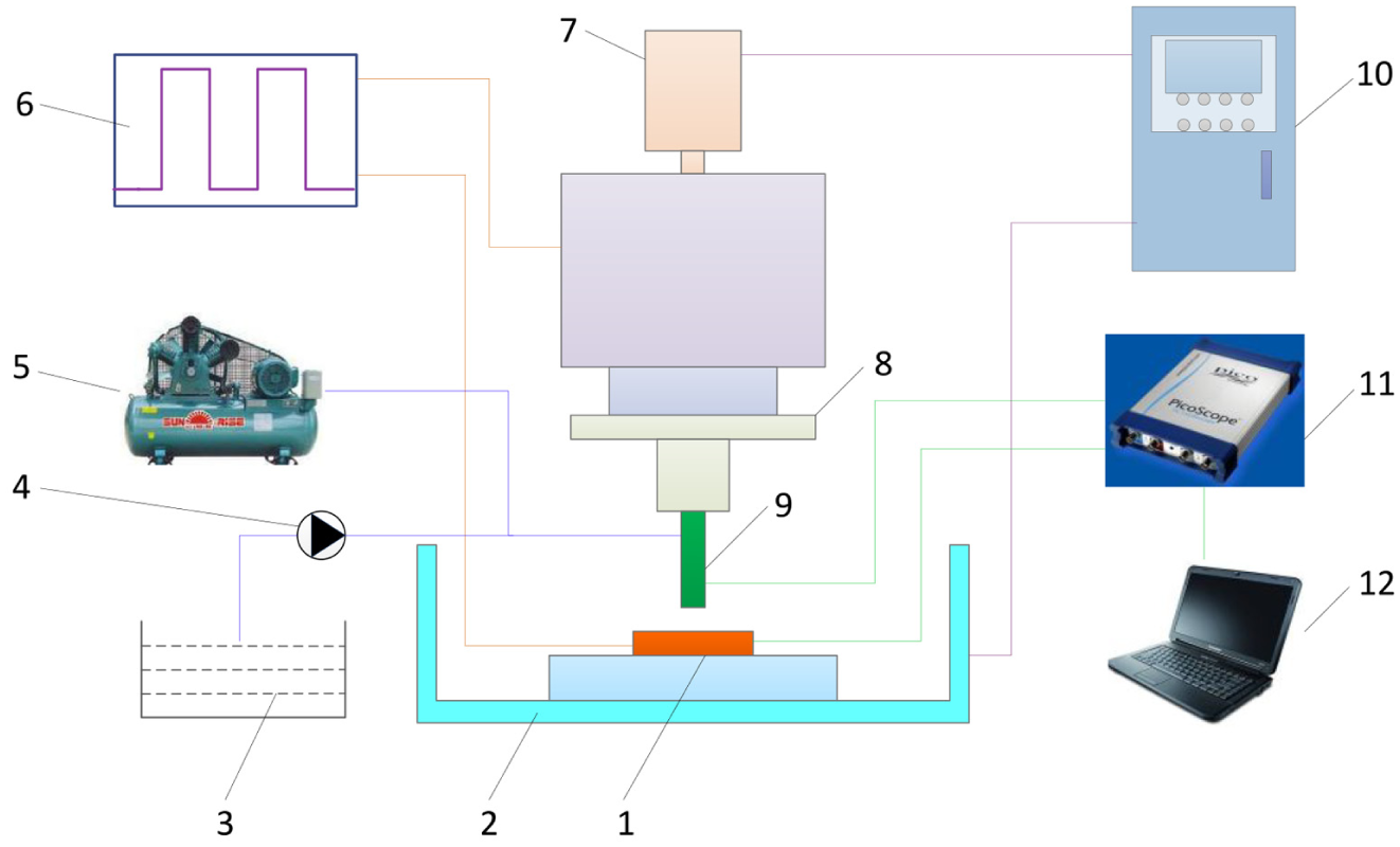
Basic experimental setup.
Experimental principle
SEAM is a method of melting and removing materials by means of excited discharge groups between tool electrodes and workpiece electrodes under the action of a certain proportion of gas–liquid mixed dielectric with pressure. 22 The schematic diagram of SEAM is shown in Figure 2. When the pulse power supply is loaded between the tool electrode and the workpiece, a large amount of charge will be generated on the surface of the two poles. As tool electrode continues to feed, the distance between the poles decreases. Current carriers in the dielectric will collide and the collided carriers will be separated, leading to avalanche collision ionization. At this time, the dielectric is broken down and a discharge channel is rapidly formed between the two poles.
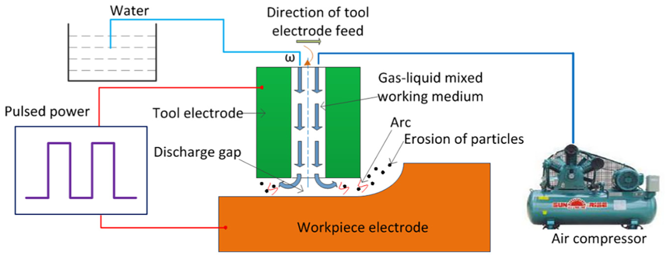
Schematic diagram of SEAM.
In the discharge channel, charged particles collide with the workpiece surface at high speed, which converts kinetic energy into heat energy and transfers it to the workpiece, so that the workpiece surface is rapidly melted and gasified. In the process of heat transfer, part of the heat is absorbed by the dielectric in the gap and will be discharged from the gap together with the corrosion products of the material. In the pulse interval, the charged particles in the dielectric will combine again quickly to form neutral particles, and the dielectric properties of the medium will be restored.
In short, a complete arc discharge consists of four processes: dielectric ionization, discharge channel formation, material melting and gasification, and deionization.
Experimental process
To study the influence of the polarity effect on SEAM, the MRR, tool mass ratio wear (
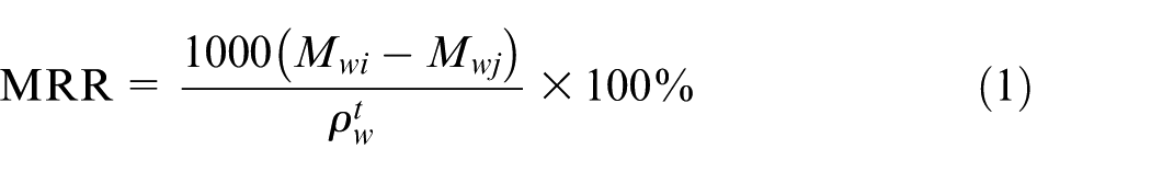
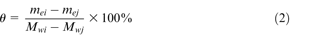
where
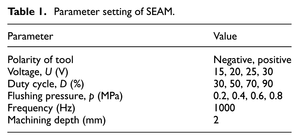
Parameter setting of SEAM.
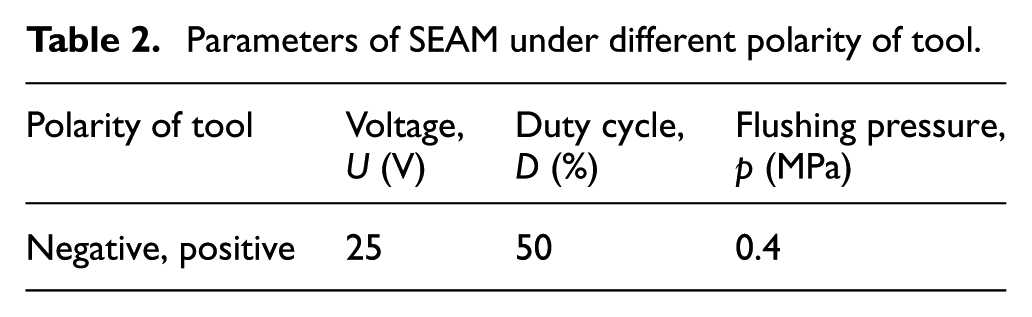
Parameters of SEAM under different polarity of tool.
Experimental results and analysis
Comparison of the influence of voltage
The influence of voltage on SEAM under different polarity conditions is shown in Figure 3. In negative SEAM, the MRR increases rapidly with the increase in voltage. When the voltage is 30 V, the maximum MRR is 261.4 mm3/min. This is because the increase in voltage is conducive to the breakdown of dielectric, which increases the average arc discharge time, that is, the arc discharge energy increases, so the MRR increases. However,
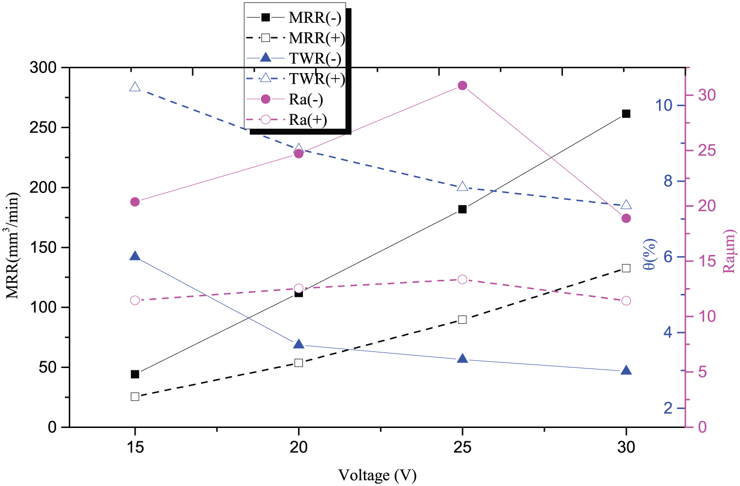
Influence of voltage under different tool polarity on SEAM performance (D = 50%, p = 0.4 MPa).
In positive SEAM, the trends of MRR,
According to the findings, it is concluded that tool-negative SEAM can obtain higher MRR and lower
Comparison of the influence of duty cycle
The influence of duty cycle on the machining performance of SEAM under different tool polarity is shown in Figure 4. The results show that MRR,
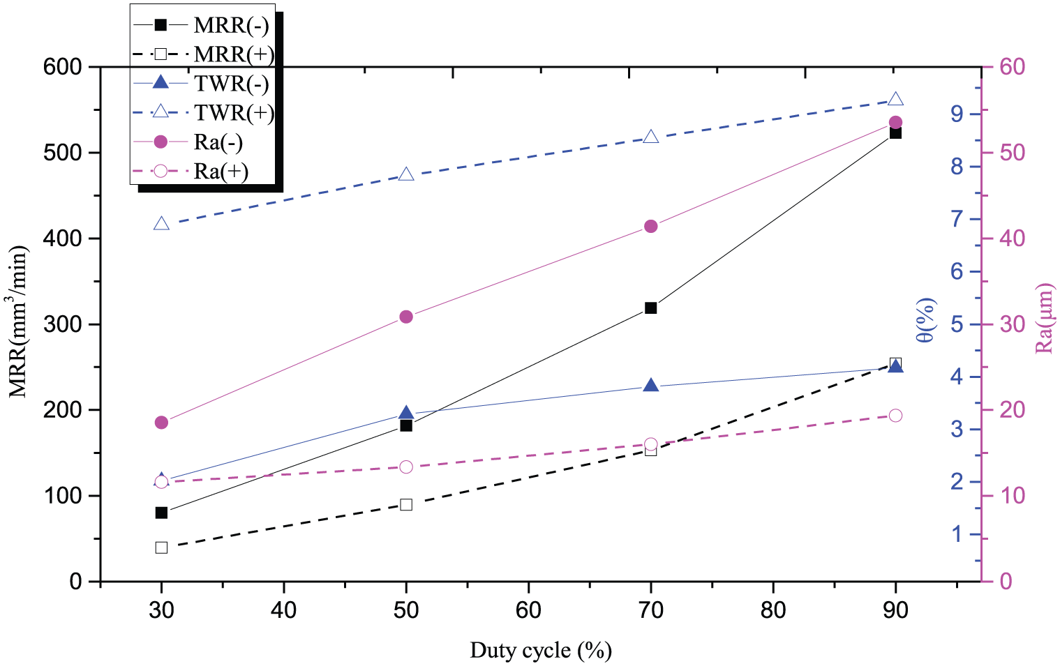
Influence of duty cycle under different tool polarity on SEAM performance (U = 25 V, p = 0.4 MPa).
Comparison of the influence of flushing pressure
As seen in Figure 5, if the tool electrode is either negative polarity machining or positive polarity machining, the influence of flushing pressure on SEAM performance is approximately the same, that is, MRR and Ra decrease with the increase in flushing pressure. When the flushing pressure is greater than 0.4 MPa, the decreasing speed of MRR and Ra tends to be gentle gradually. This is attributed to the increase in the arc-breaking effect caused by the increase in flushing pressure, which in turn decreases the probability of discharge. Although the average discharge time and the arc discharge energy both decrease, the increase in flushing pressure is conducive to the rapid discharge of etched particles, and the stability of the machining process is improved. The distribution of discharge pits is more uniform and the surface quality of the workpiece is improved, so the decreasing trend of MRR and Ra gradually slows down. In addition,
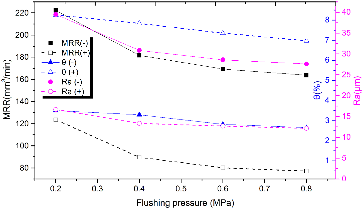
Influence of flushing pressure under different tool polarity on SEAM performance (U = 25 V, D = 50%).
Macroscopic analysis of GH4169 surface
To more intuitively observe the effect of changing tool polarity on the surface change of GH4169 in SEAM, the following experiments are carried out, and the parameters are set as shown in Table 2. Compared with Figure 6(a) and (b), it can be seen that in negative SEAM, the surface roughness of the GH4169 is higher, and the surface brightness is darker than that of positive SEAM. The measured surface roughness, Ra, is about 30.86 μm, which is approximately 2.3 times that of positive SEAM. As shown in Figure 6(c), regardless of whether the tool is negative or positive, the end-face profile of GH4169 after SEAM is almost U-shaped. This is due to the sharp discharge effect and skin effect in SEAM, which alter the geometric shape of the tool. In addition, the tool edge loss and axial loss of positive SEAM are greater than that of negative SEAM, so that the actual machining depth of positive SEAM is less than that of negative SEAM. This also indicates that the total volume of the material removed by positive SEAM is less than that of negative SEAM. In conclusion, positive SEAM can obtain better surface quality, while negative SEAM will cause less tool wear.
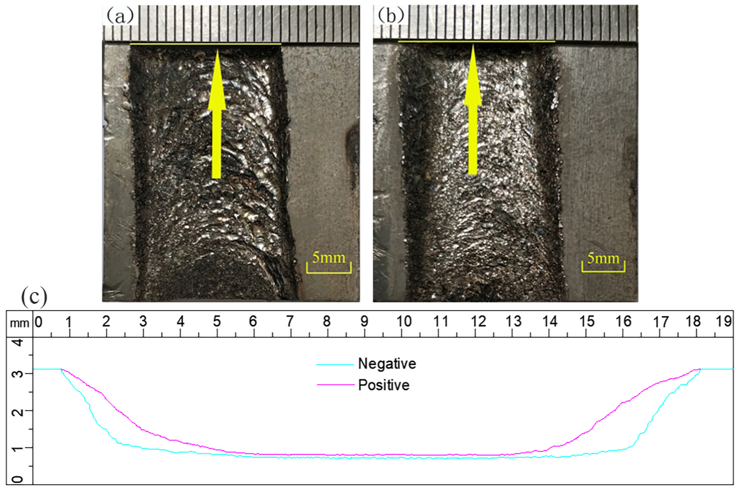
Surface and end-face profile of GH4169 under different tool polarity: (a) negative, (b) positive, and (c) end-face profile of GH4169 after SEAM.
Analysis of interelectrode voltage–current waveform
To investigate the influence of interelectrode voltage–current waveform, a PicoScope 5204 oscilloscope is used to collect voltage–current signals in the SEAM process. The parameters are set as shown in Table 2, and the GH4169 is machined by changing tool polarity. The variation of voltage–current waveform between electrodes is shown in Figure 7, in which channel U represents the voltage waveform, and channel i is the current waveform.
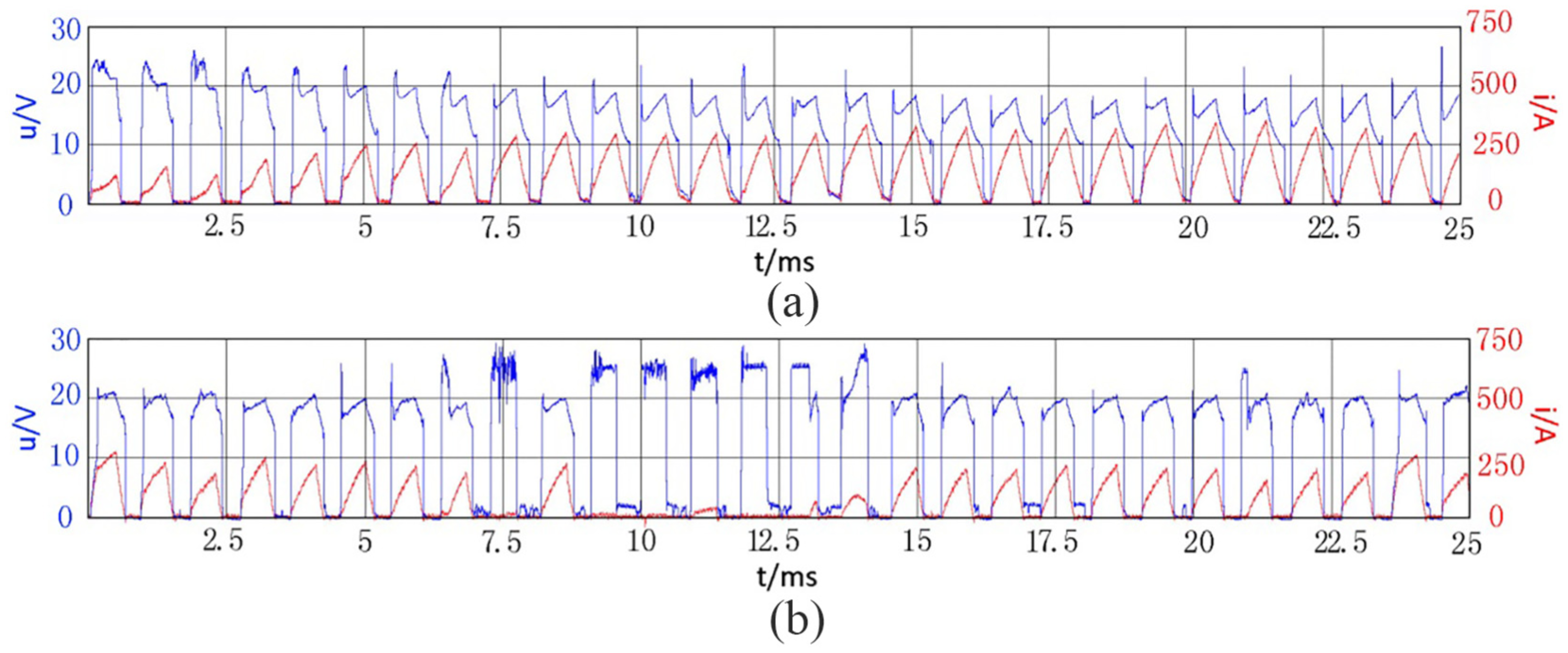
Voltage–current waveform between electrodes in different tool polarity machining: (a) negative and (b) positive.
As illustrated in Figure 7, there are significant differences in the voltage–current waveforms between the electrodes of different tool polarity in the machining process. In continuous discharge machining, compared with negative SEAM, the discharge frequency of positive SEAM is lower. The arc plasma is affected by flushing pressure, and the effect of arc breaking is more obvious. In addition, the peak current of negative SEAM is obviously higher than that of positive SEAM, so the arc plasma energy of negative SEAM is also larger. This finding presents strong proof of the high efficiency of negative SEAM.
GH4169 surface integrity analysis
To further study the influence of the polarity effect on SEAM, the surface integrity of GH4169 after SEAM is analyzed from a micro perspective in the following section. The experimental parameter settings are shown in Table 2.
Scanning electron microscope analysis
The microstructure of the GH4169 surface after SEAM is presented in Figure 8. As seen in Figure 8(a), the surface discharge pits of GH4169 are large and deep, with prominent edges and rough surfaces. In Figure 8(b), the surface of GH4169 is relatively smooth, no obvious pits are found, and there is little residual material to be cooled again, indicating that positive SEAM can achieve better surface quality. To further understand the variation of different tool polarity machining, lager multiple scanning electron microscope (SEM) is used to observe the surface of GH4169 after SEAM. Compared with Figure 8(c) and (d), it can be seen that there are micro-cracks on the surface of the GH4169 after SEAM. The micro-cracks on the surface after negative SEAM are wide and long, while the micro-cracks on the surface of GH4169 after positive SEAM are narrow and short. These cracks are most likely the result of the heat generated by the arc discharge and the cooling effect of the flushing fluid. This finding also reflects that heat generated by arc discharge and the rapid cooling effect of flushing fluid in negative SEAM have a more significant effect on local stress concentration.
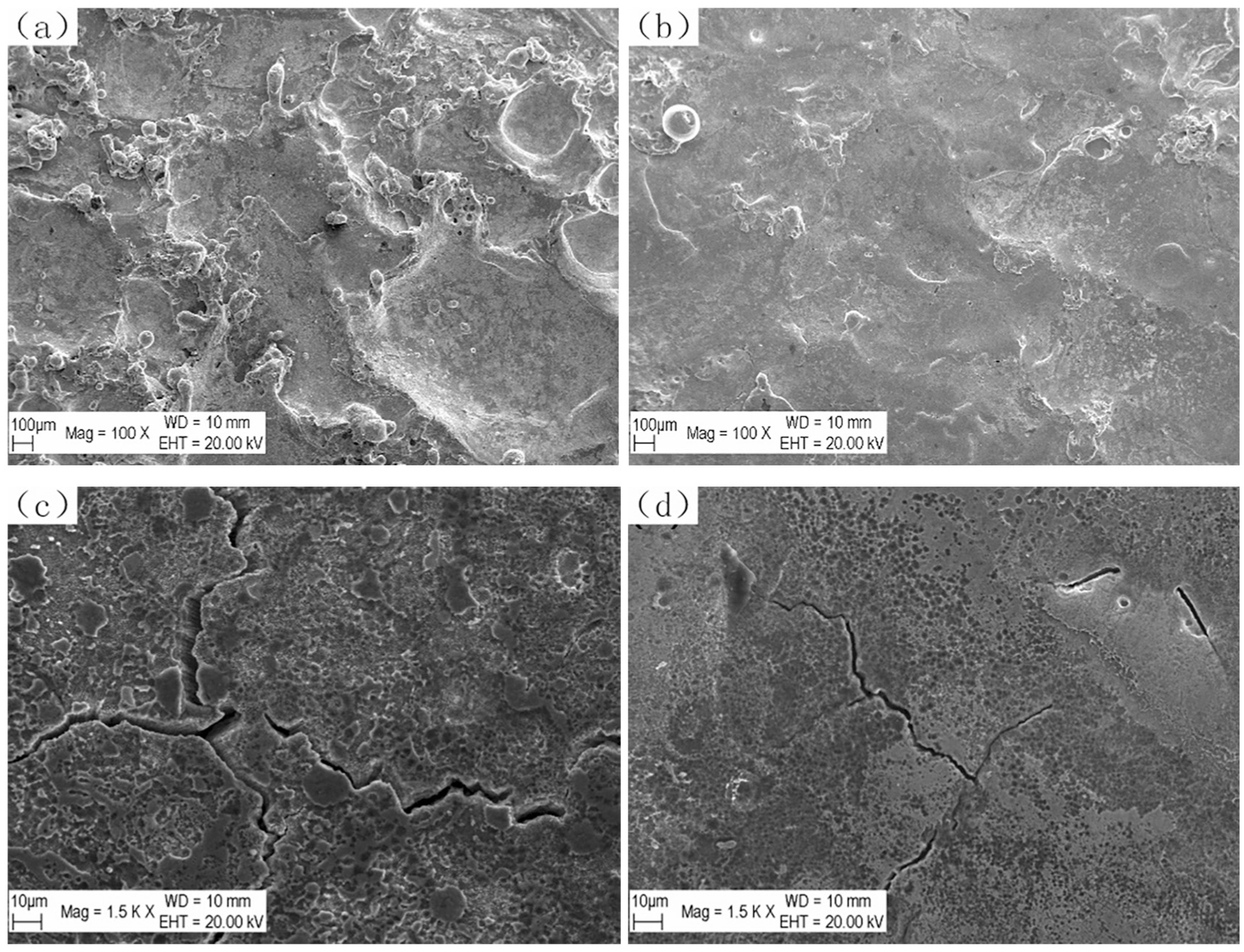
Microstructure of GH4169 surface after SEAM: (a, c) negative; (b, d) positive.
Energy dispersive spectroscopy analysis
Material erosion in SEAM is a very complex process, which is a mixture of electric field force, magnetic force, thermal force, and hydrodynamic force. Numerous physical and chemical reactions occur during this process. For this study, the chemical composition of GH4169 surface after SEAM is analyzed by energy dispersive spectroscopy (EDS). As illustrated in Figure 9, when tool polarity varies, the chemical composition of the GH4169 surface is different. The results show that the C element on the surface of GH4169 increases after both positive and negative polarity machining, which is due to the adhesion of C element from the graphite electrode to the GH4169 surface during SEAM. The contents of Cr, Fe, Ni, Nb, and Mo elements in positive SEAM are higher than those in negative SEAM, indicating that GH4169 is closer to the matrix material after positive SEAM. This result also indicates that GH4169 still maintains good machinability after positive SEAM. In addition, the surface O element of GH4169 machined by negative SEAM is higher than that machined by positive SEAM, demonstrating that the surface of GH4169 machined by negative SEAM is easier to be oxidized than that machined by positive SEAM in air.
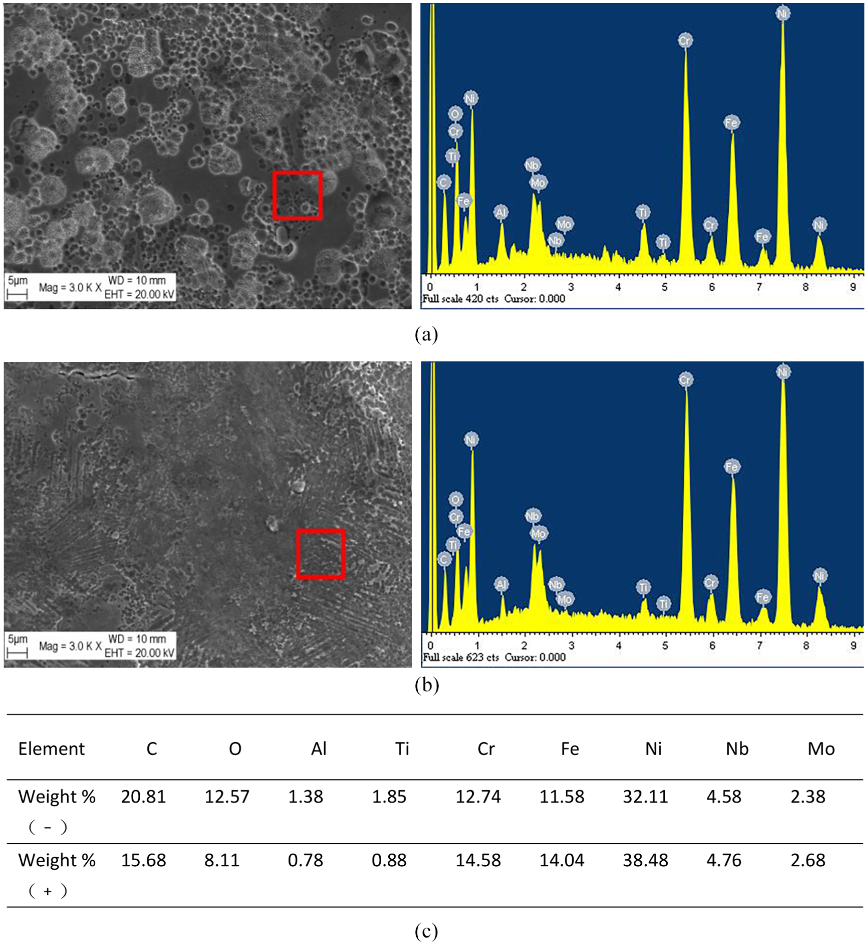
Surface analysis of GH4169 after different tool polarity machining: (a) negative, (b) positive, and (c) surface chemical components of GH4169.
Heat-affected layer analysis
The metallographic structure of nickel-based superalloy GH4169 consists of
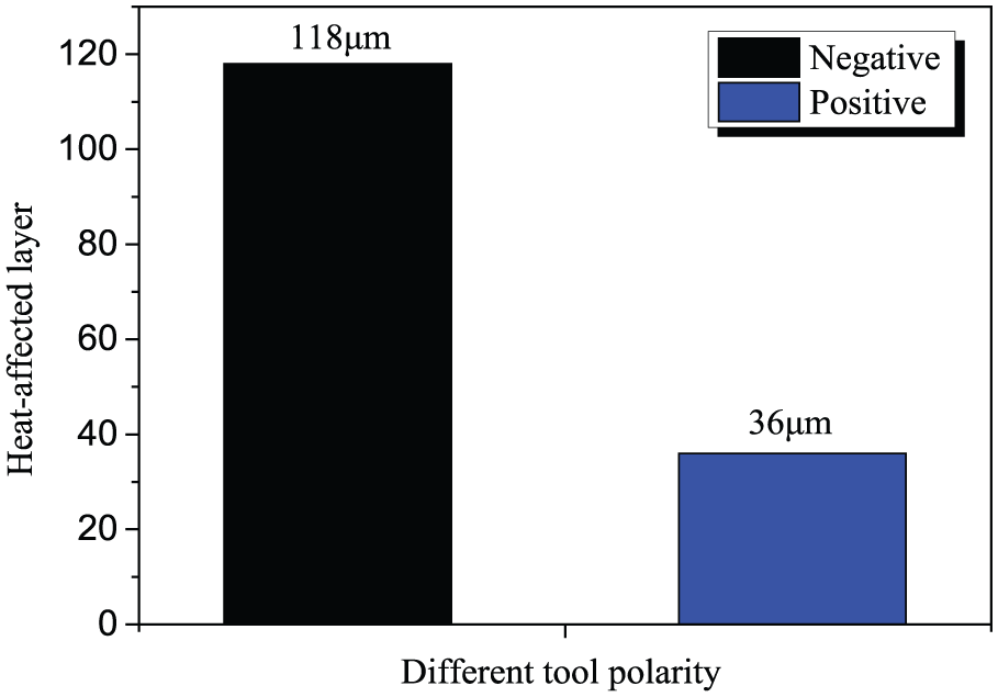
Heat-affected layer thickness after SEAM.
The heat-affected layer is enlarged to obtain the grain variation diagram as shown in Figure 11. It can be observed that the grains gradually coarsen from the workpiece surface to the matrix direction, and long strips of structure appear near the matrix, which prevents the further growth of the matrix structure. Grain boundaries are interspersed with granular crystals, which play a strengthening role. Near the surface of the workpiece, because of the high temperature, the strengthening phase will be rapidly melted, so the grain growth process is almost not hindered by the strengthening phase. With the increase in the distance from the workpiece surface, the heat absorbed by the structure decreases gradually, and the strengthening phase cannot be completely melted. The melted particles are doped in the crystal, which hinders the growth of the grain.
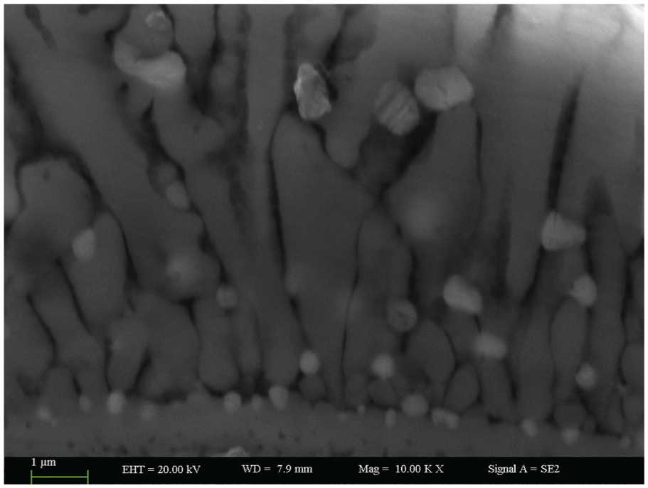
Grain variation in heat-affected layer.
Microhardness analysis
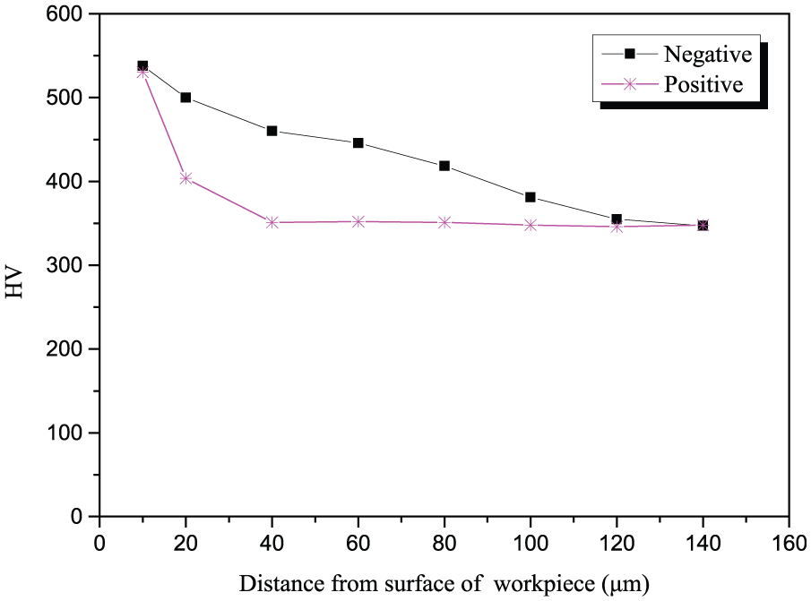
The GH4169 metallographic specimens were loaded on the HXD-1000TB video digital Vickers hardness tester with a force of 100 g lasting for 15 s. The hardness data were measured as shown in Figure 12, which shows that the hardness decreases gradually with the increase in distance from the surface, and eventually tends to be flat. This is because the structure absorbs more energy closer to the surface, and the grain can be fully refined, thus increasing hardness. In negative SEAM, when the distance from the surface of the GH4169 is more than 120 μm, the hardness decrease trend is gentle, while in positive SEAM, it tends to be gentle beyond 40 μm. This is due to the heat-affected layers of negative polarity and positive polarity machining, which are 118 and 36 μm, respectively. Beyond the heat-affected layer, the matrix structure is at a greater distance from the GH4169 surface, thus the structure fails to absorb more heat and the grain is not refined, so the hardness is low.
Microhardness change of GH4169 surface.
Conclusion
This study analyzed the influence of voltage, duty cycle, and flushing pressure on SEAM under different tool polarity. The influence of the polarity effect on SEAM was then determined from macro and micro perspectives. The following conclusions were obtained:
Under the same conditions, higher MRR and lower
After SEAM, the end-face profile of GH4169 is approximately U-shaped, and the actual machining depth of negative SEAM is greater than that of positive SEAM.
In continuous discharge machining, the arc-breaking effect of positive SEAM is more obvious than that of negative SEAM.
After negative SEAM, the surface discharge pits of GH4169 are large and deep, and the surface is rough. However, the surface of GH4169 is smooth after positive SEAM, and no obvious pits are found.
Compared with negative SEAM, GH4169 after positive SEAM is found to maintain relatively good machinability.
The thickness of the GH4169 heat-affected layer after negative SEAM is larger than that of positive SEAM.
After SEAM, the microhardness of the GH4169 surface decreases first and then tends to be flat with the increase in distance from the GH4169 surface.
Footnotes
Declaration of conflicting interests
The author(s) declared no potential conflicts of interest with respect to the research, authorship, and/or publication of this article.
Funding
The author(s) disclosed receipt of the following financial support for the research, authorship, and/or publication of this article: This research was supported by the key research and development projects in the autonomous region (Grant No. 2018B02009-4) and the Natural Science Foundation of China (Grant No. 51765063).