
Abstract
Compacted graphite iron is one of the existing structural materials for automobile engines that is difficult to machine using the conventional machining method. This article focuses on the effects of cutting fluid with different pressures and jetting paths on machined surface integrity in the machining of compacted graphite iron. The machined surface integrity is compared between dry cutting and 6 MPa wet cutting at cutting speeds of 100–500 m/min and the influences of the cutting fluid jetting paths (pouring, 2–6 MPa) along the tool flank face and rake face on the machined surface integrity are evaluated. Microstructure, roughness, work hardening, and residual stresses of the machined surface are also analyzed. The results suggest that cutting fluid can reduce surface defects and improve the machined surface finish. Of note, the roughness reduction effect decreases with an increase in fluid pressure; the roughness Ra of 6 MPa wet cutting with the cutting fluid jetting along the flank face is 0.2–1.56 µm lower than that seen with dry cutting in the cutting speed range of 100–500 m/min. The degree of hardening in 6 MPa wet cutting is 11%–19% lower than in dry cutting, and cutting fluid enhances the formation of residual compressive stress in the machined surface which reaches its maximum at 3 MPa.
Introduction
Compacted graphite iron (CGI) is an ideal material with high strength paired with high thermal cycling load due to its good mechanical, physical, and casting performance characteristics. 1 It is now the major material used in the fabrication of the cylinder block and cylinder head of modern diesel engines. 2 In the production of CGI, the machined surface generally has different degrees of surface roughness and cracks. These unfavorable defects affect the accuracy, wear resistance, corrosion resistance, and fatigue strength of CGI parts, resulting in their poor performance and reduced life.3–5
A variety of investigations on the subject of CGI machinability have been carried out in the past few decades. Souza et al. 6 machined CGI with a ceramic cutting tool with feed rate (f) of 0.2 mm/rev; cutting depth (ap) of 1 mm; and cutting speed (Vc) of 200, 350, and 500 m/min. Their study showed that the machined surface roughness decreases as the cutting speed increases. However, elsewhere, when the cutting parameters are f = 0.50 mm/rev; ap = 0.2 mm; and Vc = 160, 180, and 200 m/min, it was revealed that the surface roughness increases initially and then decreases as the cutting speed increases. 7 Skvarenina and Shin 8 used laser-assisted machining (LAM) to improve the machinability of CGI, determining that machined surface roughness is about 5% higher than that of conventional machining. Stalbaum 9 carried out a turning experiment on CGI cylinder liners with cubic boron nitride (CBN) tools in a computer numerical control (CNC) turning center using modulation-assisted machining (MAM) techniques, with the results showing that MAM had a lower average surface roughness than that seen in conventional machining at the same cutting length.
Cutting fluid is used in the machining of metallic materials to obtain better machinability. Kuram et al. 10 explored variations of the surface roughness of austenitic stainless steel (AISI 304) by alterations in cutting parameters and cutting fluid types. Their results revealed that the sunflower cutting fluid (a mixture of two surfactants) is the most efficient medium to reduce surface roughness as the spindle speed increases. The use of the sunflower cutting fluid made surface roughness reach its minimum at f = 0.08 mm/rev, while the use of the commercial vegetable cutting fluid makes surface roughness reach its minimum at a spindle speed of 720 r/min. Wang et al. 11 carried out a cutting experiment research on CGI with f = 0.15 mm/rev, ap = 0.9 mm, and Vc = 70 m/min. The cutting performances of four coated carbide inserts for dry and oil-on-water (OoW) cooling cuttings were compared, with results indicating that the cutting temperature and surface roughness lessen with the increase of water content in the internal oil-on-water (IOoW) condition. However, IOoW (1.2 L/h) has a better cooling effect than IOoW (0.6 L/h) and IOoW (1.8 L/h), which can reduce heat accumulation and ensure good lubrication performance, resulting in the least tool wear rate and lowest adhesion at IOoW (1.2 L/h). Habak and Lebrun 12 explored the effects of using high-pressure cutting fluid (20, 50, and 80 MPa) on the surface integrity of austenitic stainless steel (AISI 316L) in turning tests with cutting parameters f = 0.1 mm/rev, ap = 1 mm, and Vc = 80 and 150 m/min. Ultimately, their results suggested that the high-pressure cutting fluid reduces the surface roughness in a slight manner as compared with dry cutting. However, the roughness value increased slightly with the increase in fluid pressure. Also, work hardening and surface residual stresses decrease strongly in high-pressure cutting.
Cutting fluid is accurately sprayed to the machining area by controlling the injection pressure and jetting path in high-pressure cooling machining. High-pressure cutting fluid can break the resistance of high-pressure steam (known as the Leidenfrost phenomenon) effectively due to its higher impact energy. So, as compared with ordinary pouring fluid, high-pressure cutting fluid has better cooling, lubrication, and cleaning effects in metal machining.13–15 In this study, cutting fluids with different pressures (0–6 MPa) are used in the machining of CGI with different cutting speeds. The cutting fluid is directly injected into the cutting zone along the flank and rake face of the cutting tool. The machined surface integrity characteristics (e.g. surface defects, roughness, work hardening, and residual stresses) of the workpiece in different cutting conditions are then investigated and compared.
Experiments
Experimental material
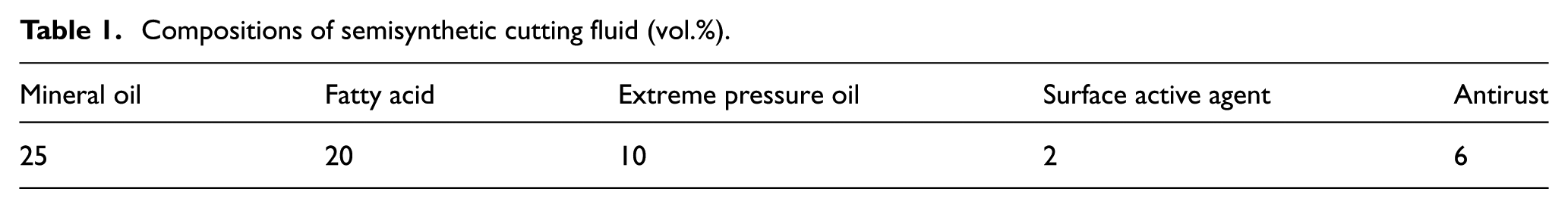
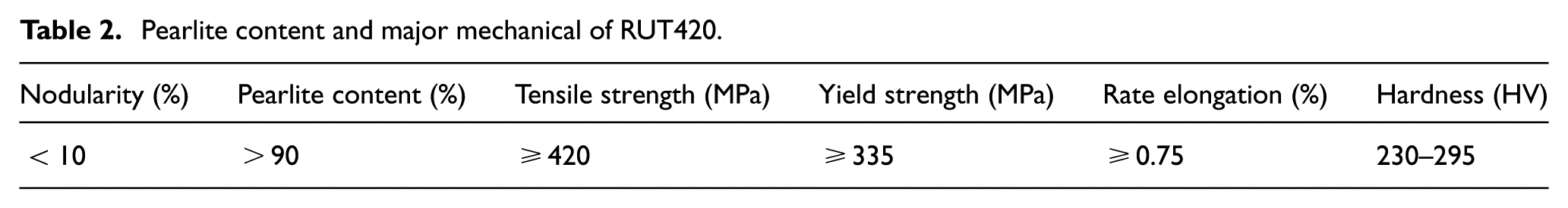
Turning tests were carried out on a CNC lathe, which boasts a power of about 5.5 kW and a maximum rotation speed of the spindle of about 3000 r/min. A coated cemented carbide insert (WNMG080408-EF YBC251) was used in the turning tests. The type of cutting fluid in the turning tests was a semisynthetic cutting fluid. The ingredients of the cutting fluid are listed in Table 1. The grade of CGI used in the turning tests was RUT420. The major mechanical and physical properties of RUT420 are listed in Table 2.
Compositions of semisynthetic cutting fluid (vol.%).
Pearlite content and major mechanical of RUT420.
Experimental methodology
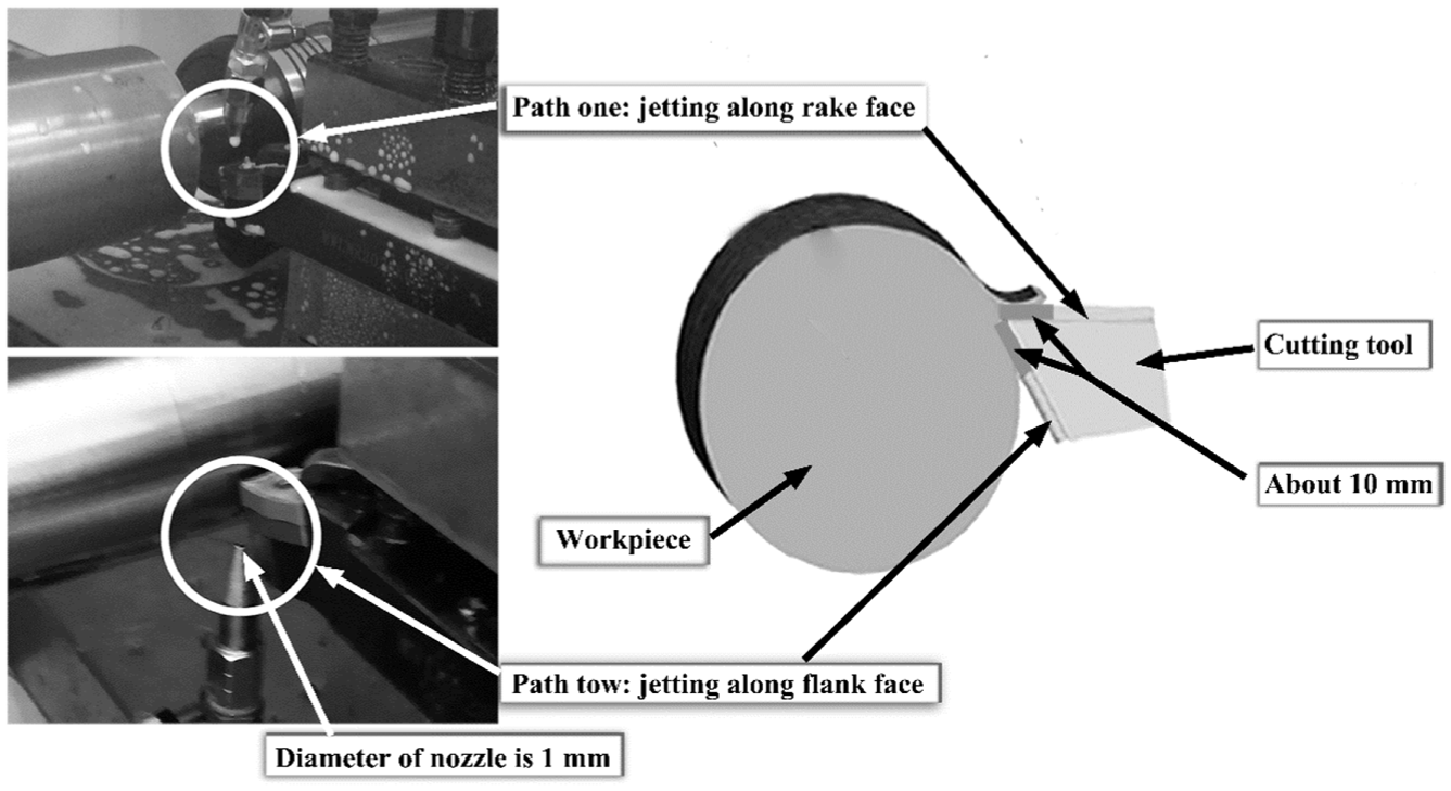
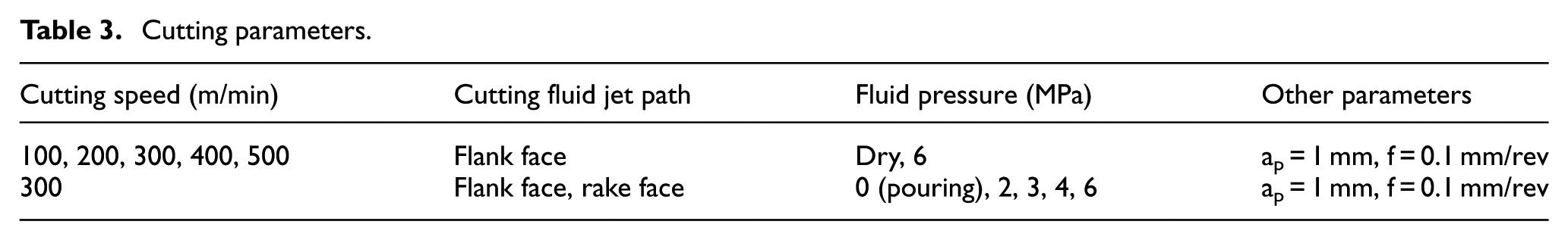
To ensure unity and integrity, the cutting fluid pressures used in this research were determined according to a previous published paper. 14 To explore the effects of cutting fluids with different pressures and jetting paths on the machined surface integrity, dry cutting, pouring cutting fluid, and cutting fluid with fluid pressures of 2, 3, 4, and 6 MPa were used in the cutting experiments. The cutting fluids with different pressures were jetted into the cutting zone via two paths, specifically along the rake face and along the flank face of the cutting tool, respectively (Figure 1). The diameter of the nozzle was 1 mm (Figure 1). A constant distance of 10 mm from the nozzle to the cutting edge was maintained during the experiment. 14 The cutting parameters and the application strategy of the cutting fluid are listed in Table 3. Five cutting speeds were used for dry cutting and 6 MPa wet cutting with the cutting fluid jetting along the flank to explore the pressure effects of the cutting fluid on the machined surface integrity. At Vc = 300 m/min, cutting fluid pouring (0 MPa) and application with pressure (2, 3, 4, 6 MPa) were used in the two different jetting paths to explore the jetting path effect of cutting fluid on the machined surface integrity. To avoid the influence of tool wear 16 on the machined surface integrity, a new insert was used and the cutting length was limited to 160 m for each cutting, where there was no obvious tool wear. The machined surfaces were sampled at the middle point of the cutting length.
Experimental setup.
Cutting parameters.
Following the completion of the experimental machining, wire electrical discharge machining was performed to obtain machined surface samples from the machined RUT420 bar. Then, the samples were ground and polished. The microhardness of the samples was subsequently tested with the testing parameters: Vickers hardness, pressure of 10 GF, and pressure holding time of 20 s. Micromorphology and roughness of the machined surface were analyzed by scanning electron microscopy and roughness testing instrument. The residual stress of the machined surface was measured using the hole-drilling method. 17
Results and discussion
Surface microstructure and roughness
Figure 2 presents the machined surface microstructures in dry cutting and 6 MPa wet cutting with cutting fluid jetting along the flank face at cutting speeds of 100, 300, and 500 m/min. In dry cutting (Figure 2(a)–(c)), the major defects on the machined surface include inclusions, protuberances, microgrooves, side-flows, redeposited materials, and micropits. In contrast, the major surface defects in wet cutting are microgrooves and side-flows (Figure 2(d)–(f)). The inclusions and protuberances are of external particles. 18 The redeposited material is in the form of semi-molten chips deposited on the machined surface. 19 The inclusions, redeposited materials, and protuberances seen in 6 MPa wet cutting are much less than those observed in dry cutting at the same cutting speeds. This may be due to the enhanced clean effect of the 6 MPa cutting fluid, which can easily remove the exotic particles and restrain the formation of the redeposited materials. In addition, the side-flows between neighboring cutting paths in machined surfaces in 6 MPa cutting (Figure 2(d)–(f)) are more apparent than those in dry cutting. Notably, the number of microgrooves in the machined surface in dry cutting decreases as the cutting speed increases. However, the microgroove configuration in 6 MPa wetting cutting seems to exhibit no change with an increase in the cutting speed.
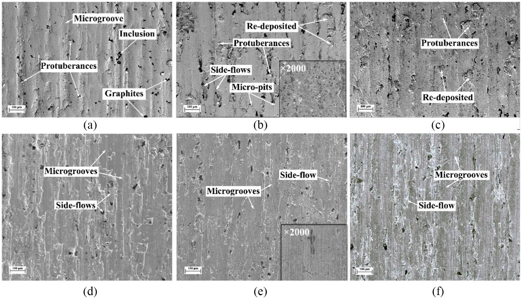
The machined surface microstructure of CGI in dry cutting and 6 MPa wet cutting with cutting fluid jetting along the flank face: (a) dry cutting, Vc = 100 m/min; (b) dry cutting, Vc = 300 m/min; (c) dry cutting, Vc = 500 m/min; (d) 6 MPa wet cutting, Vc = 100 m/min; (e) 6 MPa wet cutting, Vc = 300 m/min; and (f) 6 MPa wet cutting, Vc = 500 m/min.
Figure 3 shows the surface microstructures in pouring (0 MPa) cutting and 3 and 6 MPa wet cutting with cutting fluid jetting along the flank and rake face at the constant cutting speed Vc = 300 m/min. Protuberances can also be seen on the machine surface in pouring cutting (Figure 3(a)) but were removed from the machined surface in 3 and 6 MPa cutting (Figure 3(b)–(e)). With the increase in pressure of the cutting fluid jetting along the rake face (Figure 3(a)–(c)), the side-flow in the machined surface becomes more obvious. This may be due to the strengthened cooling effect seen at high-fluid pressures, which pushes the cutting temperature lower, making it more difficult for the side-flow to occur. Figure 3(d) and (e) shows that the cutting fluid jetting along the flank of the cutting tool has no obvious defect-elimination effect in the machined surface in comparison with the cutting fluid jetting along the rake face.
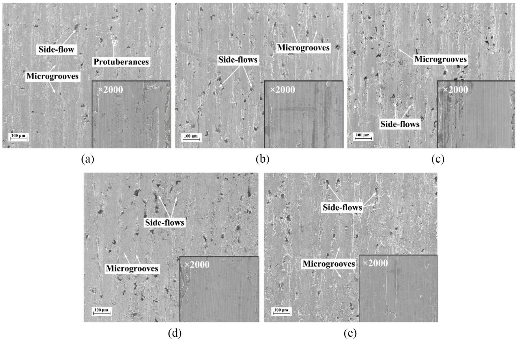
Surface microstructures of CGI in cuttings with different fluid pressures and jetting paths at Vc = 300 m/min: (a) pouring; (b) 3 MPa, jetting along the rake face; (c) 6 MPa, jetting along the rake face; (d) 3 MPa, jetting along the flank face; and (e) 6 MPa, jetting along the flank face.
Figure 4 shows the surface roughness in different cutting conditions. The surface roughness value of dry cutting and 6 MPa wet cutting goes downward as the cutting speed increases (Figure 4(a)). The surface roughness of wet cutting is obviously lower than that in dry cutting. In dry cutting, the surface roughness reduces quickly with the cutting speed increasing from 100 to 300 m/min and then flattens out with further increases in cutting speed. However, the reduction of surface roughness in wet cutting is slow as the cutting speed increases. The roughness value reaches its minimum at Vc = 500 m/min for both the dry and 6 MPa wet cutting situations. The roughness value of 6 MPa cutting is 0.2–1.56 μm lower than that in dry cutting at the same speed ranges.
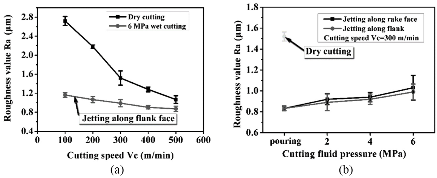
Surface roughness in different cutting conditions: (a) dry cutting and 6 MPa wet cutting with cutting fluid jetting along the flank at different cutting speeds and (b) surface roughness in cuttings with cutting fluid jetting in two paths at different fluid pressures.
Figure 4(b) shows the trend of surface roughness with the increase of fluid pressure in different jetting paths and given the cutting speed Vc = 300 m/min. As compared with the dry cutting, the use of cutting fluid can effectively reduce the surface roughness. The maximum difference between dry and wet cuttings occurs at pouring (0 MPa), which is about 0.75 μm. It is interesting that the surface roughness values of the cutting fluid jetting along the flank face and rake face exhibit a slightly upward trend as the fluid pressure increases, which hints that higher cutting fluid pressures are not helpful for reducing surface roughness. At the same cutting speed range, the roughness values of the cutting fluid jetting along the flank face are slightly lower than those of that jetting along the rake face.
According to Wang et al., 11 Habak and Lebrun, 12 and Su et al., 14 high-pressure cutting fluid may take effect in machining through three ways: first, the high-pressure cutting fluid can break the resistance of high-pressure steam (Leidenfrost effect) effectively as a result of its higher impact energy and achieve effective lubrication. 14 Second, high-pressure cutting fluid can go deep into tool–workpiece and tool–chip contact zones and atomize very fast, which takes away the cutting heat in the zones in time; 14 finally, high-pressure cutting fluid can effectively reduce the bonding between the cutting tool and workpiece and thus reduce tool wear.11,12,14 These effects can restrain the formation of built-up edges and scales and remove redeposited work material and protuberances on the machined surface. This may make the surface roughness values of wet cuttings lower than those seen in dry cutting (Figure 4(b)). The cutting fluid jetting along the flank face can directly take away the cutting heat just in the tool–workpiece contact zone and subsequently offers a better effect in lubrication and cooling than jetting along the rake face. This leads to the surface roughness of the cutting fluid jetting along the flank face being lower than that of that jetting along the rake face (Figure 4(b)). However, the decrease in the vicinity temperature of the contact zone makes the material therein difficult to flow, which may increase the roughness of the machined surface (Figure 4(b)).
Machined surface hardening
Figure 5(a) and (b) shows the microhardness in dry cutting and 6 MPa wet cutting with cutting fluid jetting along the flank face at a cutting speed ranging from 100 to 500 m/min. Figure 5(c) and (d) presents the comparison of microhardness in cuttings with cutting fluid jetting along the flank and rake face at a constant cutting speed of Vc = 300 m/min and different fluid pressures. For all cutting conditions, the microhardness value decreases with an increase of the measured depth underneath the machined surface. In dry cutting (Figure 5(a)), the hardness value decreases as the cutting speed increases. The minimum depth of the hardening layer is 40 μm at Vc = 500 m/min. In 6 MPa wet cutting (Figure 5(b)), the trend of hardness value is the same at that seen with dry cutting (Figure 5(a)). However, the hardness values are smaller than the corresponding values in dry cutting. The minimum depth of hardening layer in 6 MPa wet cutting is 39 μm at Vc = 500 m/min. For wet cuttings with cutting fluid jetting along the rake face at constant cutting speed of 300 m/min (Figure 5(c)), the hardness value decreases with the increase in cutting fluid pressure. The hardness value reaches its maximum at 2 MPa and minimum at 6 MPa (Figure 5(c)). In wet cutting with the cutting fluid jetting along the flank face (Figure 5(d)), the maximum hardness value occurs at 2 MPa as well. Separately, the minimum depth of hardening layer was 46 μm at 6 MPa.
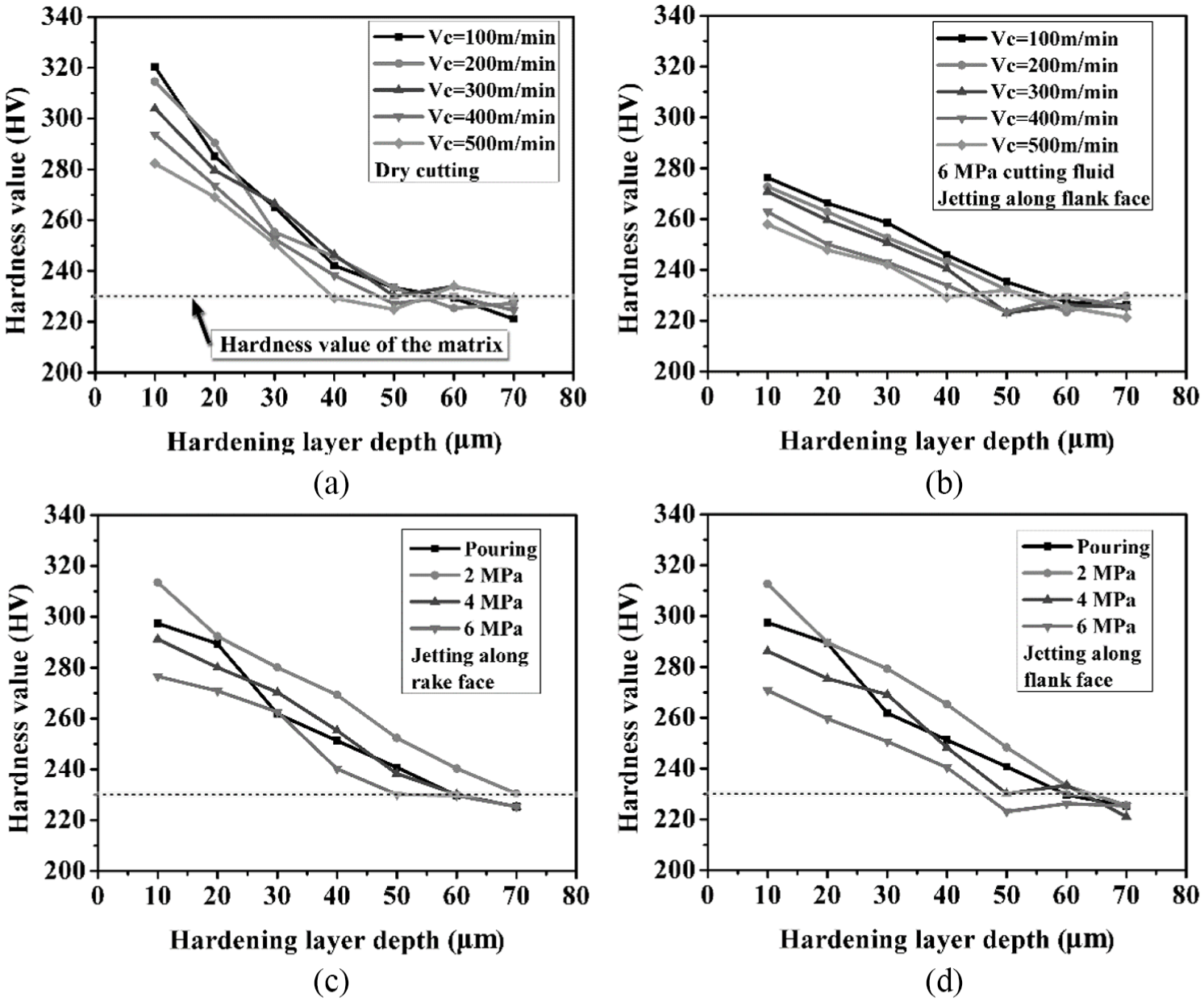
Machined surface hardness in the dry and 6 MPa wet cutting scenarios versus different cutting speeds and jetting paths: (a) dry cutting; (b) 6 MPa cutting, jetting along the flank face; (c) Vc = 300 m/min, jetting along the rake face; and (d) Vc = 300 m/min, jetting along the flank face.
Figure 6 shows the depth of hardening layer in different cutting conditions. In the dry and 6 MPa wet cuttings (Figure 6(a)), the depth of hardening layer decreases with the increase in cutting speed monotonously. At the same cutting speed, the depth of the hardening layer of 6 MPa cutting with the cutting fluid jetting along the flank face is 1–4 μm lower than that in the case of dry cutting. In wet cuttings with different jetting paths (Figure 6(b)), the depth of the hardening layer of jetting along the flank and rake face increases first and then decreases as the fluid pressure increases. It reaches its maximum at 2 MPa for both jetting paths. Of note, the depth of the hardening layer of jetting along the flank face is 4–10 μm lower than that of jetting along the rake face at each fluid pressure.
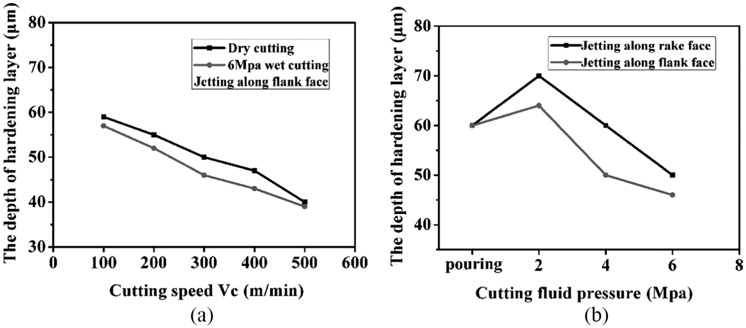
The depth of the hardening layer versus cutting speed and fluid pressure: (a) dry cutting and 6 MPa wet cutting and (b) jetting along the rake face and flank face, Vc = 300 m/min.
Figure 7 shows the degree of hardening N of the machined surface in different cutting conditions. In dry and 6 MPa wet cuttings (Figure 7(a)), the degree of hardening (N) decreases with the increase in cutting speed and reaches its minimum at Vc = 500 m/min. The N of 6 MPa wet cutting with cutting fluid jetting along the flank face is about 10%–20% at Vc = 100–500 m/min, which is lower than that in dry cutting at the same cutting speeds. The minimum discrepancy between the Ns of dry and 6 MPa wet cuttings occurs at Vc = 500 m/min. For wet cutting with different jetting paths (Figure 7(b)), both the Ns of jetting along the flank and rake face, respectively, increase with an increase in fluid pressure from 0 to 2 MPa and then decrease with the pressure further increases to 6 MPa. The values of both Ns of jetting along the flank and rake face of the cutting tool are in the range of 17%–37%. The N of jetting along the flank face is a little smaller than that of jetting along the rake face at the same fluid pressure. The maximum discrepancy between the Ns of jetting along the flank and rake face occurs at 6 MPa.
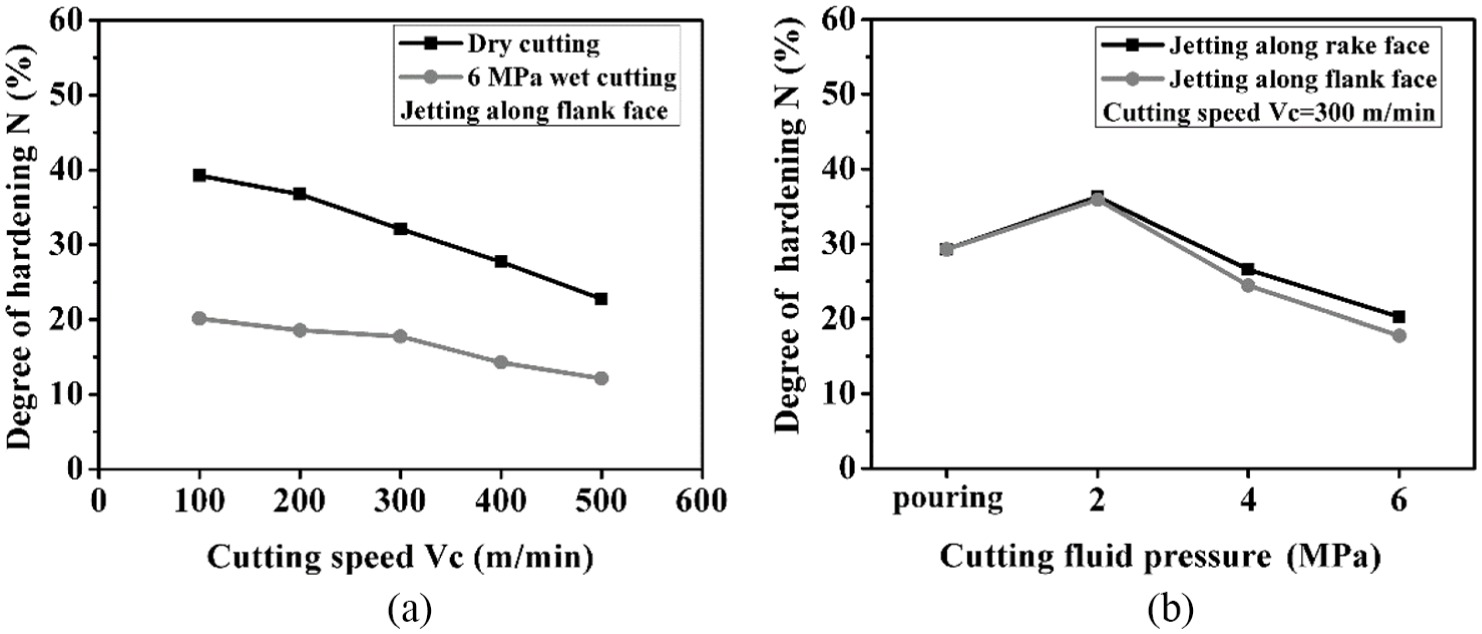
Degree of hardening N versus cutting speed and cutting fluid pressure with a depth of 10 μm: (a) dry cutting and 6 MPa wet cutting and (b) jetting along the flank and rake face.
With the increase in cutting speed, work hardening in a machined surface cannot fully develop due to a reduction in contact time between the tool and workpiece, while thermal softening is strengthened due to an increase in the temperature of the contact area. 20 This leads to the reduction of the hardening layer depth and hardness value of the machined surface (Figure 5). As shown in Figures 6(a) and 7(a), the use of 6 MPa cutting fluid did not lower the depth of the hardening layer but did reduce the degree of hardening. This may be due to the enhanced lubrication effect of the 6 MPa cutting fluid, which reduces the work hardening effect of the underlayer material of the workpiece.
The addition of cutting fluid may cause quenching effect in a machined surface when the cutting temperature is high enough at a special cutting speed. This may lead to the increase in hardness and depth of the hardening layer. However, the lubricating and cooling effects of cutting fluid increase as the fluid pressure increases. The increase in the cutting fluid lubrication effect causes a decrease in the plastic deformation in the machined surface and a resultant decrease in the hardness and depth of the hardening layer. This may be used to explain the curve trend of hardening degree N as the fluid pressure increases (Figure 7): when the fluid pressure is lower than 2 MPa, the hardening effect due to quenching on the machined surface overtakes the friction-reduction effect of the lubrication, which causes an increase in the hardness and depth of the hardening layer of the machined surface, while, when the cutting fluid pressure is higher than 2 MPa, the softening effect of lubrication outstrips the hardening effect of quenching, prompting a decrease in the hardness and the depth of the hardening layer of the machined surface. The lubrication effect of cutting fluid jetting along the flank face is better than that seen with the rake face.14,20 This leads to the depth of the hardening layer and the hardness values of the machined surface with the cutting fluid jetting along the flank face being lower than that of the rake face at the same fluid pressure.
Residual stress in machined surface
In the cases of casting, mechanical processing, and welding, the material is deformed, the properties of the material are changed, and residual stresses are generally generated.21,22 During the metal cutting processes, tensile or compressive stress which depends on the processing conditions and material performances will be caused in the machined surface. 22
The residual stress in the machined surfaces at Vc = 300 m/min with different pressures of cutting fluid jetting along the flank face are measured using the hole-drilling method. 17 Figure 8 shows that the residual stress in the machined surface is compressive stress for the given cutting conditions. The compressive stress is increased first and then decreased as the fluid pressure increases. The range of residual compressive stress value is 27.64–70.41 MPa in dry cutting and 235.173–202.105 MPa in 3 MPa wet cutting; however, the residual compressive stress value then decreases to 79.79 MPa to 112.31 MPa at 6 MPa wet cutting, which is lower than that at 3 MPa.
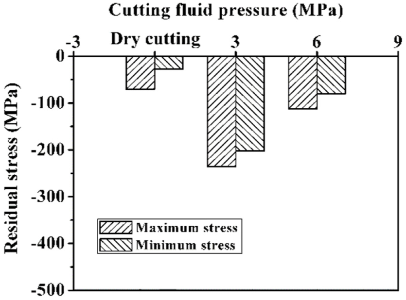
Residual stress in the machined surface at Vc = 300 m/min with cutting fluid jetting along the flank face with different pressures.
When physical properties of a material are determined, the residual stress is mainly related to the thermal stress and the depth of the hardening layer. 23 It shows that the decrease in surface temperature and heat-conduction depth or the increase in hardening layer depth can promote the formation of a compressive stress residual. 23 As shown in Figure 6, the depth of the hardening layer at dry cutting and 3 MPa wet cutting are 50 and 57 μm, respectively. This results in the increase in residual compressive stress from 0 to 3 MPa. However, that the residual compressive stress values at 6 MPa are lower than those at 3 MPa is perhaps due to that the hardening layer depth at 6 MPa (46 μm) is lower than that at 3 MPa (57 μm).
Conclusion
In this study, dry and wet cutting with cutting fluid at different fluid pressures and jetting paths were considered in the machining of CGI to explore the effects of fluid pressures and jetting paths on machined surface integrity. The results of this article could provide ways to improve the control of surface integrity in the machining of CGI. The specific conclusions are as follows:
As compared with dry cutting, the addition of cutting fluids can reduce the inclusions, redeposited materials, and protuberances in (on) the machined surface. The surface roughness value in 6 MPa wet cutting decreases slightly with the increase in cutting speed. In the cutting speed range of 100–500 m/min, the roughness value of the workpiece surface machined in 6 MPa wet cutting with cutting fluid jetting along flank face is 0.2–1.56 μm lower than that in dry cutting. As fluid pressure increases, the roughness of the machined surface also increases, with the roughness value in cutting with cutting fluid jetting along the flank of the cutting tool being slightly lower than that seen with cutting fluid jetting along the rake face of the cutting tool.
In comparison with dry cutting, the addition of 6 MPa cutting fluid lowers the work hardening of the machined surface. The difference between the depth of hardening layer in 6 MPa wet cutting with fluid jetting along the flank face and the depth in dry cutting is small (about 14 μm), while the difference between the degree of hardening in 6 MPa wet cutting with fluid jetting along the flank face and the degree in dry cutting is larger (about 15%–20%). With an increase in cutting speed, the depth of the hardening layer decreases. In addition, the depth of the hardening layer increases to its maximum at 2 MPa and then decreases with the increase in fluid pressure. At the same fluid pressure, the hardening layer depth in cutting with cutting fluid jetting along the flank face of the cutting tool is 4–10 μm lower than that of jetting along the rake face.
The addition of cutting fluid enhances the formation of residual compressive stress in the machined surface, albeit in nonmonotonic form. The residual stress reaches its maximum at 3 MPa and then decreases with further increase in cutting fluid pressure. This may be due to the complex competitions ongoing between the cooling and lubrication effects of the cutting fluids with different pressures as well as work hardening and thermal softening effects at different cutting speeds.
Footnotes
Appendix 1
Declaration of conflicting interests
The author(s) declared no potential conflicts of interest with respect to the research, authorship, and/or publication of this article.
Funding
The author(s) disclosed receipt of the following financial support for the research, authorship, and/or publication of this article: This work was supported by the Key Research and Development Plan of Shandong Province (Grant No. 2018GGX103023) and National Natural Science Foundation of China (Grant No. 51675289).