
Abstract
This article presents a new type of bi-material coin with a polymer centre and a metal ring. The polymer-metal coin is fabricated by combination of coin minting and joining by forming in a single die stroke. The design of the coin is based on an analytical model built upon plasticity theory and plastic instability of circular plates under uniform radial edge compression. The analytical model and the bi-material coin concept are supported and validated by means of finite element modelling and experimentation. Destructive tests for pushing the polymer centre out of the metal ring demonstrate the effectiveness of the mechanical joint resulting from the interface contact pressure between the polymer and the metal. The new bi-material coin was developed to obtain new aesthetic effects for the collection market, and its polymer core can additionally be used for other applications such as the incorporation of advanced security features in high-denomination coins.
Introduction
Proof coins for collection purposes make use of a very restricted set of metals that are mainly taken from groups 10 and 11 of the periodic table, after exclusion of the radioactive (Ds and Rg) metals.
The main reasons behind the choice of metals belonging to the above-mentioned groups of the periodic table are corrosion and wear resistance, high fracture toughness and good formability at room temperature resulting from the fact that all these metals have face centred cubic (FCC) crystal structures. Another important reason is the fact that some of these metals (Pd, Pt, Ag and Au) are very expensive and, therefore, appropriate for high-denomination coins for collectionism and investment.
Globalization and the opportunity of selling high-denomination coins around the world justify the reason why mints are nowadays strongly committed to the development of innovative coins made from alternative materials. This trend is here to stay as it was recently shown by the internationally awarded ‘Chinese Porcelain Vase Qing Dynasty’ coin produced by the Mint of Poland 1 and issued by Niue South Pacific Island in 2016 that incorporates a fine porcelain relief etched on the reverse of a gold coin (Figure 1(a)).
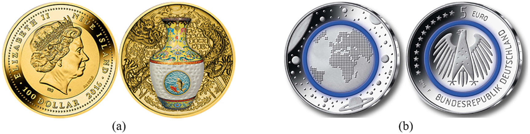
The first attempt to use polymers as alternative coining materials was made in 2015 by the German Central Bank 2 who issued the 5 Euro ‘Planet Earth’ coin (Figure 1(b)). Although ‘Planet Earth’ may be considered the first polymer-metal coin, the use of polymer is marginal and limited to a relatively thin ring. This first utilization of polymers in coin minting is entirely different from that employed in tokens for shopping trolleys, which are produced by plastic injection moulding.
Under these circumstances, the main purpose of this article is to give a step forward, extending the technology of coin minting to bi-material coins having a large area ratio between the polymer centre and the outer metal ring, with high reliefs imparted on the surfaces of the polymer centre. These are two major differences from the ‘Planet Earth’ coin that justify the need to develop a methodology for designing and validating the new proposed bi-material coins.
The design is based on an analytical model developed by the authors for selecting the appropriate geometries of the polymer and metal blanks, and for estimating the force to disassemble the coin by pushing the centre out of the ring. The accuracy of the analytical model and the overall feasibility of the bi-material coin concept are validated by means of finite elements and experimentation.
Because the number of publications in coin minting is relatively scarce and because the aims and scope of this article are a novelty in the field, there is not much to say about previous work done by other researchers. Still, Kiran and Shaw 3 developed an analytical model that allowed understanding coin minting as a net-shape precision forming process involving indentation, gross upsetting and interaction between adjacent relief coin features. The model was developed for metal coins under plane strain deformation conditions and the reliefs were approximated by simple saw tooth profiles characterized by a pitch and a feature included angle.
In the following year, Delamare and Montmitonnet 4 applied the upper bound method to develop an analytical model for calculating the energy and shape of a blank to strike a metal coin with a central circular design and an outer annular legend. Finally, Brekelmans et al. 5 applied the upper bound method to set up an analytical model to calculate the pressure for producing a conical axisymmetric relief in the centre of a metal coin. This publication was also the first to apply finite elements in coin minting.
Ever since this pioneering application, the utilization of finite elements evolved from simple two-dimensional models into the current three-dimensional models running in high performance computers, which solve the complex relief contact features that are typical of coin minting and provide accurate predictions of material flow, distribution of major field variables and evolution of the force with die stroke.
However, despite the above-mentioned advances, there are no analytical models and finite element investigations focused on the design and fabrication of polymer-metal coins. This is confirmed in the state-of-the-art review in science and technology of coin minting that was included in a recent paper by Alexandrino et al. 6
The step forward in the bi-material polymer-metal coin concept disclosed in a provisional patent application 7 and the proposed analytical model are the innovative footprints of this article. In particular, the analytical model allows selecting the interference between the polymer centre and the metal ring, determining the onset of plastic instability of the polymer centre, calculating the interface contact pressure after unloading and estimating the force that is needed to disassemble the coin by pushing the centre out of the ring.
Analytical model
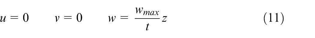
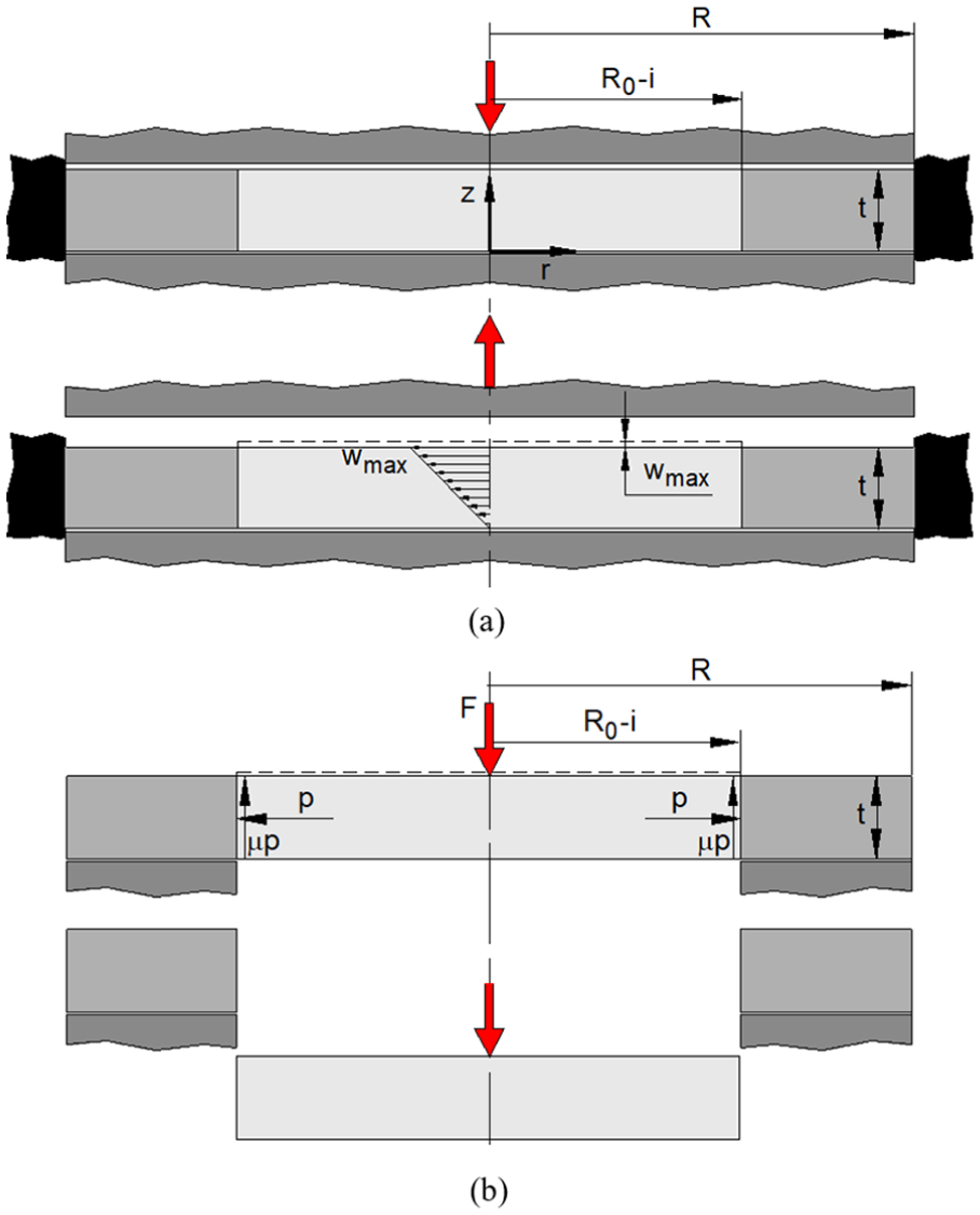
Joining by forming is carried out simultaneously with coin minting in a single die stroke to produce a mechanical lock between the polymer centre and the metal ring by interface contact pressure. The process is schematically shown in Figure 2(a), where
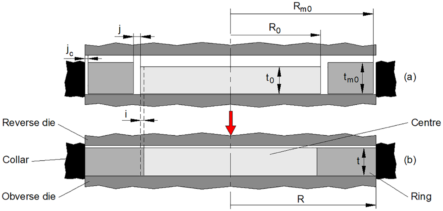
Schematic representation of the new proposed bi-material (polymer-metal) coin (a) at the beginning and (b) at the end of the die stroke with the notation utilized in the analytical model.
This is a novel fabrication process because circulating bi-metal coins (such as, for example, the 1 and 2 Euro coins) are based in form-fit joints resulting from the plastic deformation of the ring into a groove placed on the outside edge of the centre. The reason why form-fit joints cannot be used in the new type of polymer-metal coin is because they would fail by cracking of the polymer during plastic deformation of the metal ring into the groove placed on the outside edge of the polymer centre (Figure 3(a)), or by loosening due to recovery of the polymer centre after unloading (Figure 3(b)).
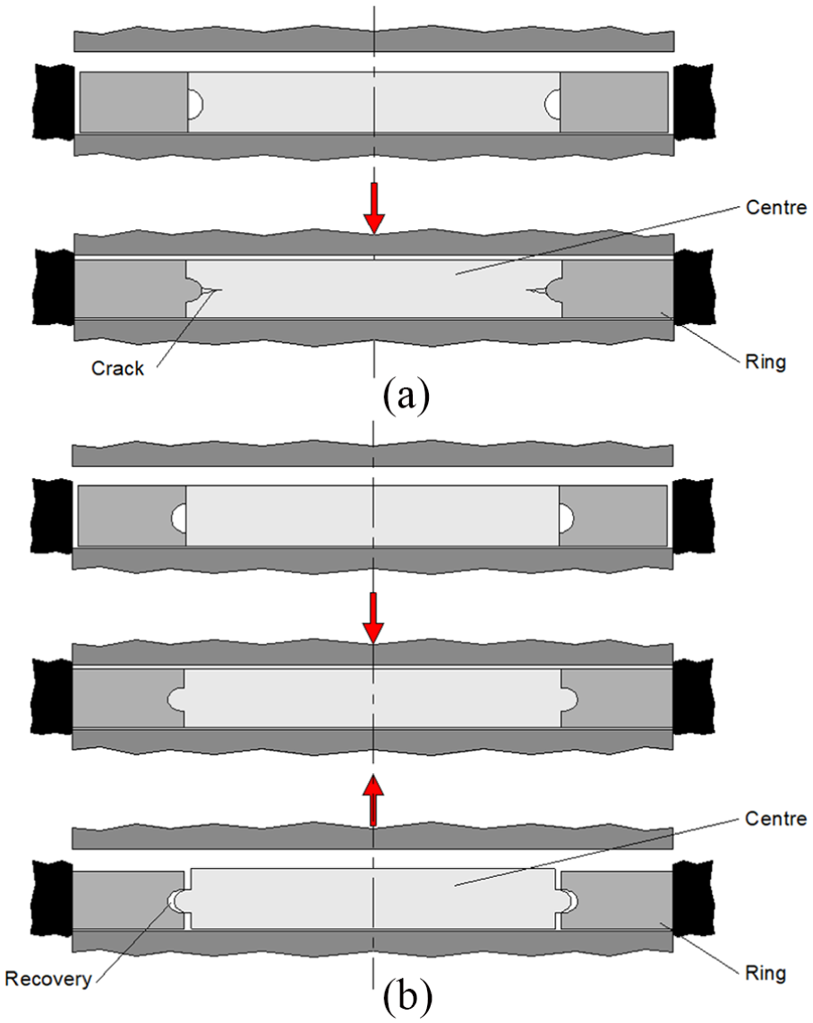
Types of failure resulting from the utilization of form-fit joints: (a) cracking of the polymer centre and (b) loosening due to recovery of the polymer centre after unloading.
Alternative joining by forming processes such as embedded cold pressing 8 or clinching 9 cannot be used to produce the mechanical lock between the polymer centre and the metal ring due to the low quality of the resulting coin surfaces with protrusions on the reverse or the obverse surfaces and to the limited formability and elastic recovery of the polymer.
Volume incompressibility
The analytical model considers plastic deformation of the polymer centre and of the metal ring to be homogeneous (i.e. plane sections remain plane) and isotropic under axisymmetric material flow conditions. The surface of the ring blank is assumed to be flat without rimmed edges. Volume incompressibility during plastic deformation of the metal ring allows writing its final thickness t as a function of the main geometric parameters of Figure 2, as follows
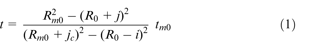
The term
The same procedure applied to the plastic deformation of the polymer centre leads to the following equation
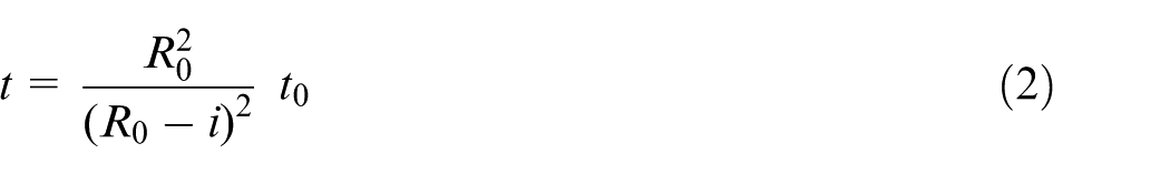
Matching equations (1) and (2) because t must be identical at the end of die stroke, one obtains the following relation between the clearance j and the interference i
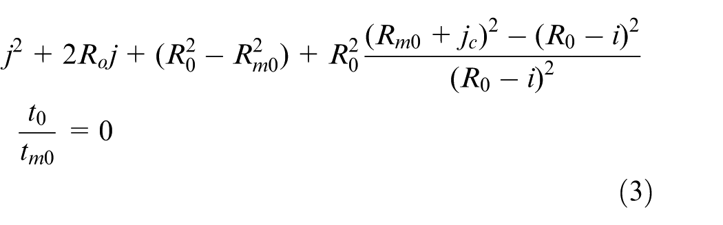
The above equation gives rise to the process curve, which is plotted as a black solid curve in Figure 4(a). The vertical-axis interception
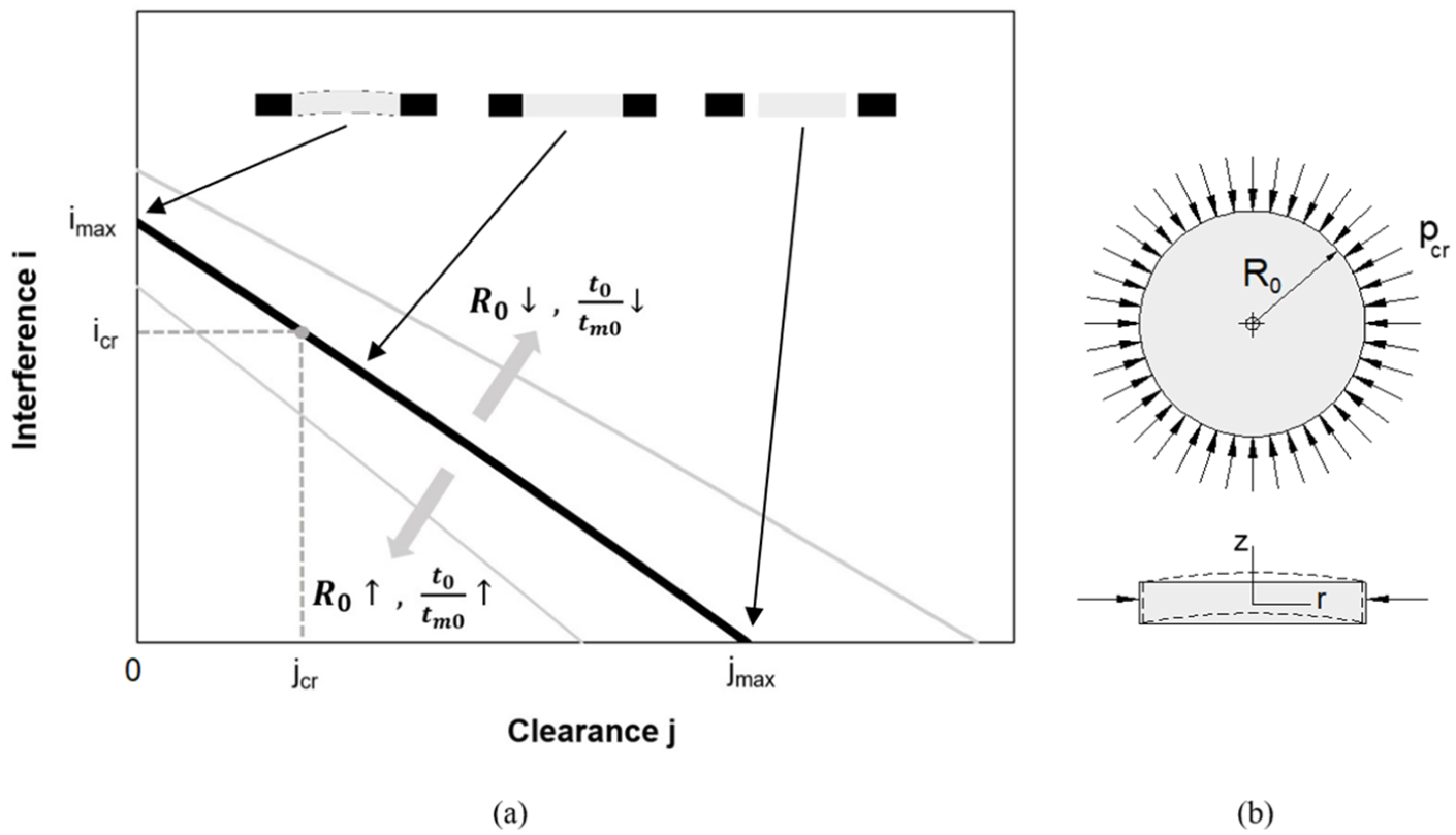
(a) Process curve showing the interference i as a function of the clearance j between the polymer centre and the metal ring blanks. (b) Schematic representation of the plastic instability of the polymer centre under uniform radial edge compression.
The process curve provides the design values for the bi-material polymer-metal coins and its position will move upwards or downwards by decreasing or increasing the initial radius
Plastic instability
Plastic instability of the polymer centre diminishes the maximum allowable interference i with the metal ring. In practical terms, this means that the process curve of Figure 4(a) is bounded by a horizontal dashed grey line containing the critical values of clearance and interference
The critical interference
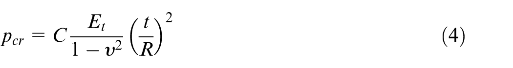
In the above equation, C is a constant related to the type of radial support (clamped vs simply supported),
Given that buckling must be triggered during the contact between the reverse die and the metal ring (there is no contact with the polymer centre at this stage, refer to Figure 2(a)), it follows that the polymer centre is subjected to bi-axial compression along the r and
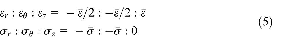
where
This allows rewriting equation (4) as a function of the original values of the radius
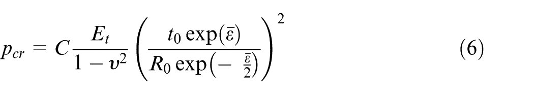
By taking into account that the critical pressure
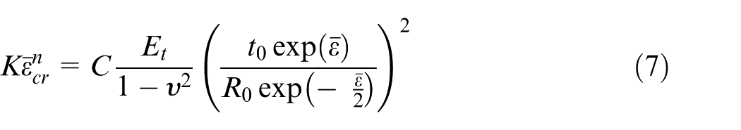
The critical strain
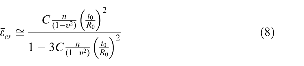
By considering the circumferential strain
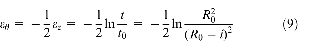
it follows that the critical interference
The critical effective strain
Elastic recovery
The analytical model is also focused on the interface contact pressure p after unloading because of the role it plays on the mechanical lock between the polymer centre and the metal ring.
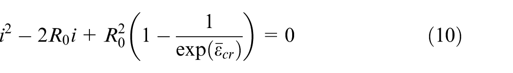
The calculation of p assumes the metal ring to be rigid and the polymer centre to unload under isotropic, linear and elastic behaviour. This prevents displacement in the radial and tangential directions and allows writing the displacement field
In the above equation,
(a) Elastic unloading of the polymer centre after coin minting with representation of its z-displacement. (b) Maximum force F to push the polymer centre out of the metal ring.
The displacement field (equation (11)) considers no shear strains and the only non-zero strain is
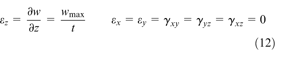
The stress field is obtained by inversion of the generalized constitutive equations for linear elasticity
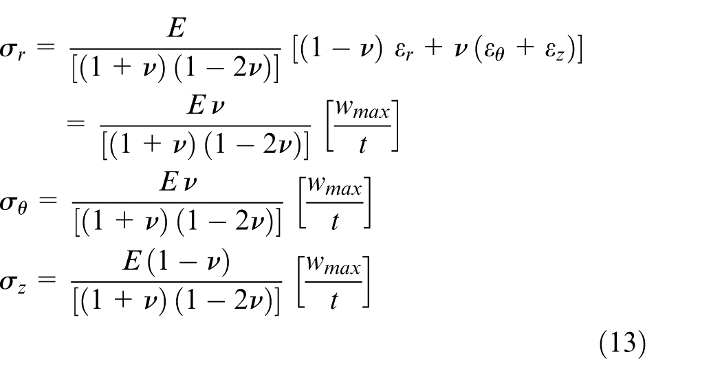
The interface contact pressure after unloading corresponds to the radial stress
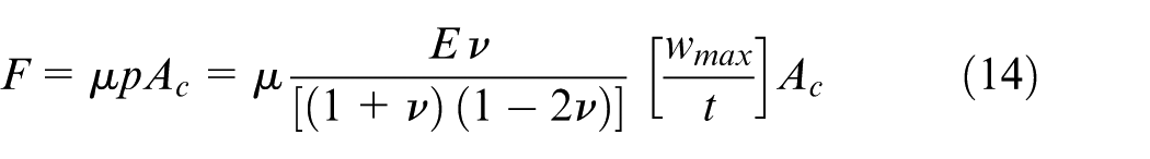
where
Finite element modelling
The numerical simulation of the coin minting process was performed with the in-house computer program I–Form. 12 The simulations made use of two-dimensional axisymmetric models because the reverse and observe dies utilized in the experiments were flat (refer to section ‘Results and discussion’). The cross sections of the polymer centre and metal ring were discretized by means of quadrilateral elements and the dies and collar were modelled as rigid objects with their contours discretized by means of linear contact-friction elements. 13
Figure 6 shows the initial mesh, dies and collar for a coin corresponding to case 4 of Table 1. The central processing unit (CPU) time for the numerical simulation of such a coin using convergence criteria for the velocity field and residual force equal to 10−3 was approximately 10 min on a computer equipped with an Intel i7-5930K CPU processor.
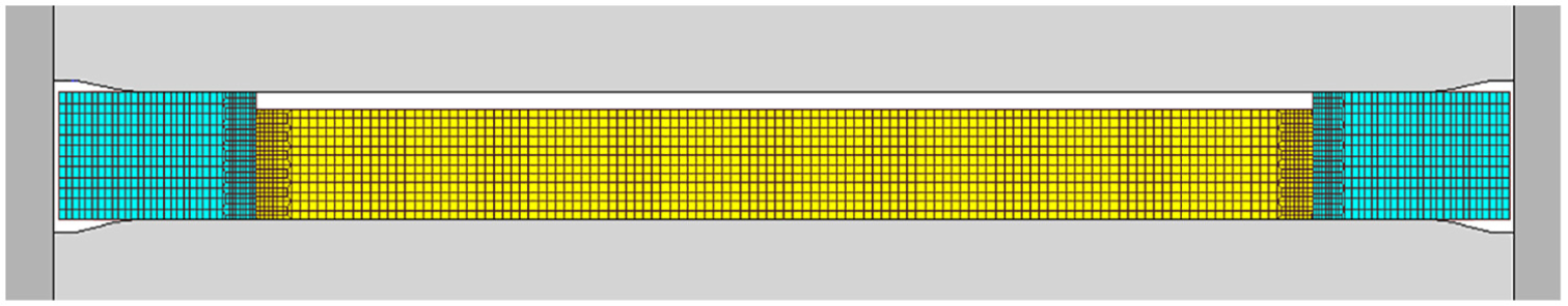
Initial mesh utilized in the finite element simulation of case 4 of Table 1.
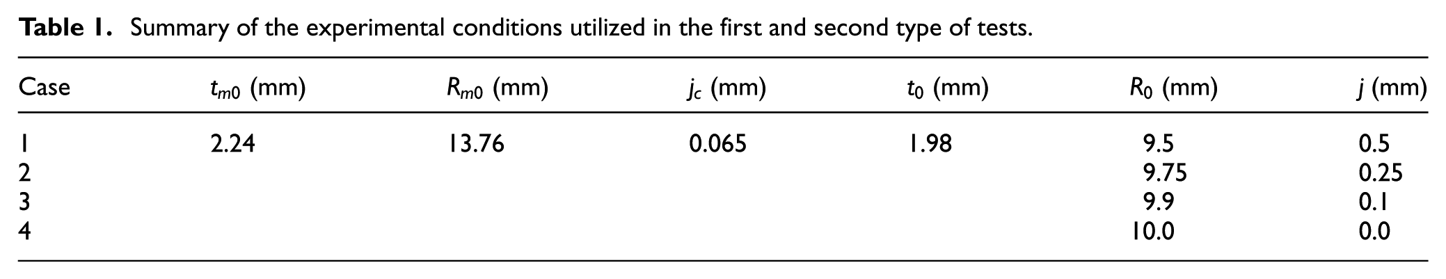
Summary of the experimental conditions utilized in the first and second type of tests.
Experimentation
Materials
The bi-material coins were fabricated with a centre made from polycarbonate (PC) and an outer ring made from a copper-nickel alloy (Cu75Ni25). The PC was supplied in the form of sheets with 1.98 mm thickness, whereas the Cu75Ni25 was supplied in the form of discs with a diameter of 29.65 mm and a thickness of 2.24 mm.
The stress–strain curve of PC was determined by means of stack compression tests and the specimens were prepared by piling up three circular discs with 15 mm diameter and 1.98 mm thickness machined out of the supplied sheets. Teflon foils were utilized in the upper and lower contact interfaces between the specimens and the compression platens.
The stress–strain curve of Cu75Ni25 was determined by means of stack compression tests that were performed by the authors in a previous work. 6 Both tests were carried out at room temperature on a hydraulic testing machine with a cross-head speed equal to 10 mm/min and the results are included in Figure 7.
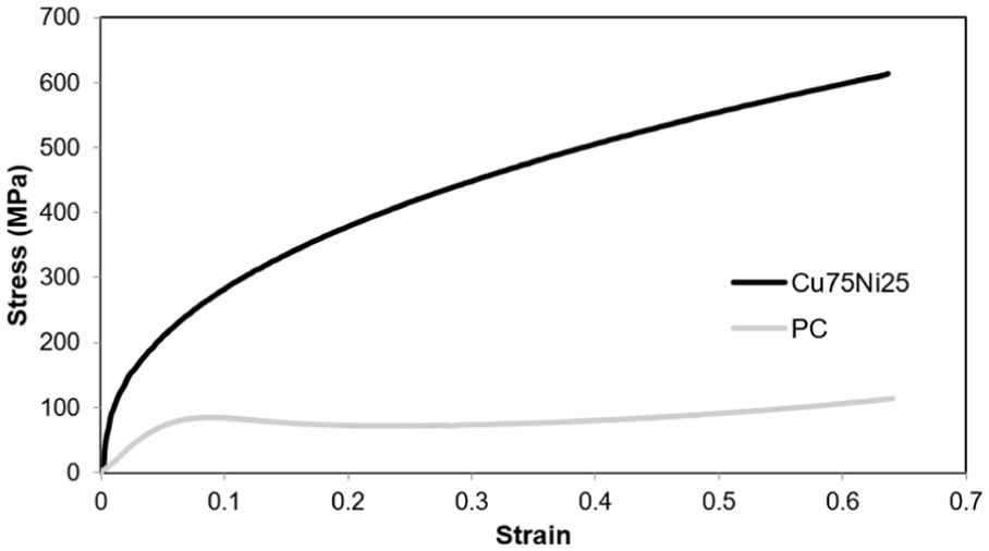
Stress–strain curves of polycarbonate (PC) and copper-nickel alloy (Cu75Ni25) determined by means of stack compression tests.
Work plan, methods and procedures
The experimental work plan involved three different types of tests. The first type of tests was performed in the laboratory coin minting tool designed by the authors that is schematically shown in Figure 8(a). The tool-workpiece contact surfaces of the plane reverse and obverse dies and the circular cylindrical inner surface of the collar are all smooth.
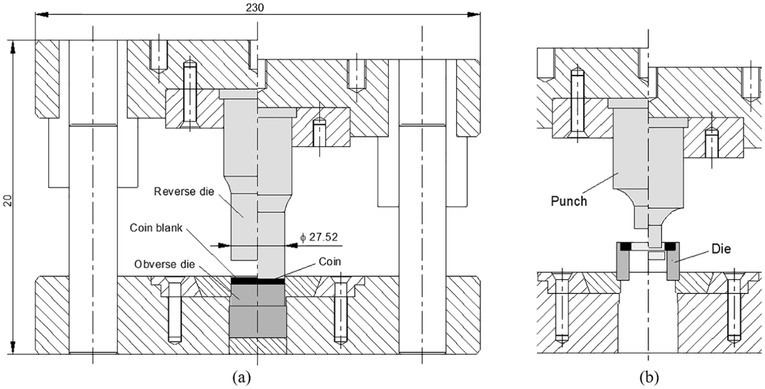
The tooling system utilized in the experiments: (a) the setup for performing coin minting and (b) the active tool components for performing the destructive push-out tests.
The experimental work plan is summarized in Table 1 and consists of four different test cases with different radius
By changing the radius
The second type of tests was aimed at determining the maximum forces that are needed to push the polymer centres out of the metal rings (Figure 8(b)). This type of destructive tests was needed to validate the effectiveness of the mechanical joint resulting from the interface contact pressure between the polymer and the metal, after unloading (Figure 5(b)).
The experiments performed in the first and second type of tests were carried out in the hydraulic testing machine that was utilized to perform the stack compression tests of PC and Cu75Ni25. A cross-head speed of 10 mm/min was employed.
The third type of tests was performed at the Portuguese state mint and made use of dies with reliefs and a collar with mills on its inner surface to validate the overall bi-material coin concept under industrial conditions.
Results and discussion
Modes of deformation
Figure 9 discloses the typical modes of deformation that were observed during the first type of tests. As seen, there are three different modes of deformation. When the clearance j between the polymer centre and the metal ring is larger than the maximum allowable clearance
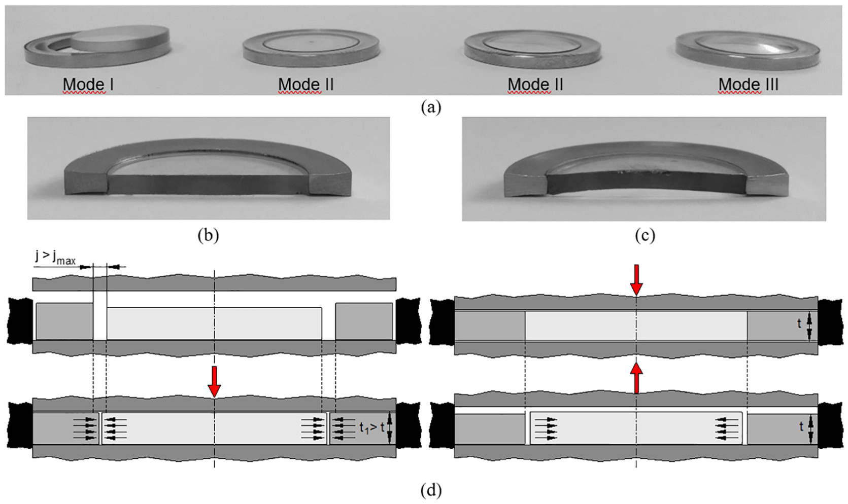
The main reason behind the occurrence of deformation mode I for
A similar result occurs when the initial thickness
Sound bi-material coins are produced under deformation ‘mode II’, which requires the clearance j between the polymer centre and the metal ring to be within the range
An inadmissible concave shape is triggered when the clearance j between the polymer centre and the metal ring is smaller than the critical clearance
Figure 10 shows the computed geometry of case 4 at the end of die stroke and after elastic unloading. As seen, finite element modelling predicts triggering of plastic instability at the polymer centre during coin minting (refer to the details included in Figure 10(a)), but the phenomenon is more easily observed after elastic unloading (Figure 10(b)). As will be shown in the following sub-section, the coin corresponding to case 4 was designed with a clearance j and an interference i located in the region of the process curve above the onset of plastic instability (refer to Figure 4(a)).
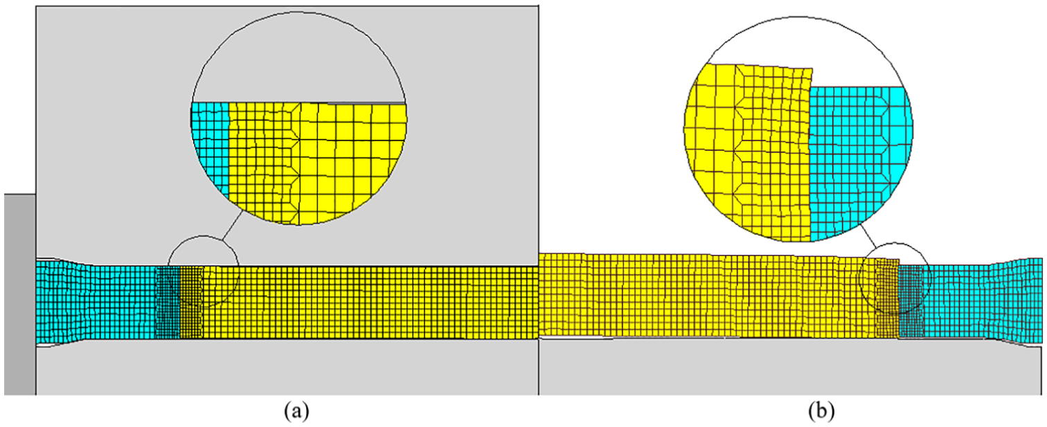
Finite element simulation of case 4 of Table 1: (a) computed mesh at the end of die stroke with details showing the development of plastic instability and (b) computed mesh after unloading.
Process curve
Figure 11(a) shows the process curve relating the interference i with the initial clearance j. The curve was derived from the proposed analytical model (refer to Figure 4(a)) using the process parameters included in Table 1. The bounded grey area around the process curve accounts for the variations of
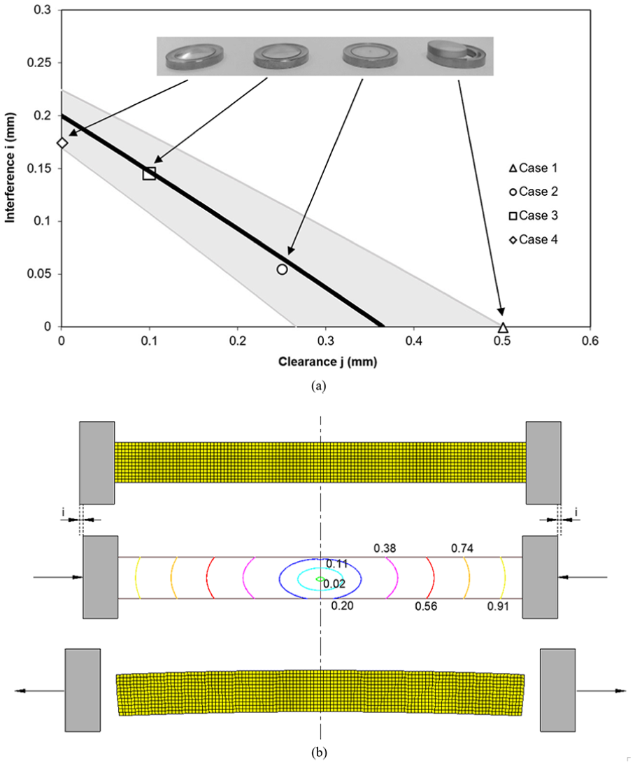
Coin minting of bi-material polymer-metal coins. (a) Process curve based on the analytical model and experimental measurements of cases 1–4 of Table 1. (b) Finite element modelling of the plastic instability by buckling of the polymer centre for case 4 of Table 1 with distribution of the normalized total velocity
A simple axisymmetric finite element model of the polymer centre corresponding to case 4 of Table 1 was subjected to uniform radial edge compression to observe the development of an asymmetric velocity field for a radial displacement equal to that of the interference i. The occurrence of a concave shape after unloading can be observed in Figure 11(b).
Direct application of equation (10) for the process conditions of case 4 provide a value of effective strain
Destructive tests
Destructive tests aimed at pushing the polymer centre out of the metal ring were carried out by replacing the coin minting setup of Figure 8(a) by the shearing punch and die setup included in Figure 8(b).
Figure 12 shows the experimental evolution of the push-out force with displacement for cases 2 and 4 of Table 1 in conjunction with the analytical estimates of the maximum force for case 2 calculated by means of equation (14). The maximum z-displacement
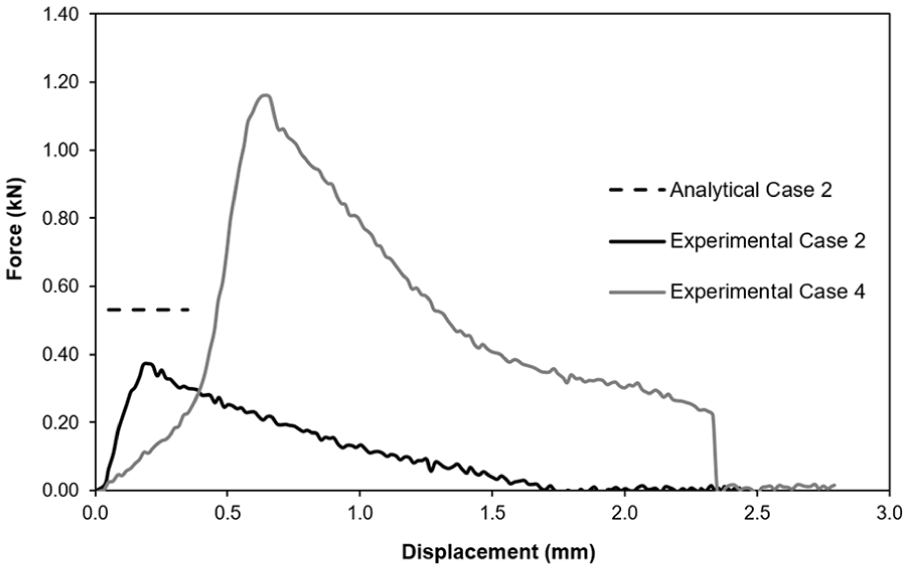
Experimental evolution of force with displacement during the destructive push-out tests of cases 2 and 4 of Table 1. The dashed lines correspond to the analytical estimates obtained by equation (14).
As seen in Figure 12, case 2 presents a steep rise of the force with displacement up to a maximum value beyond which the centre will start to be pushed out of the ring and the force will decay. Case 4 presents a similar trend with a less steep increase at the beginning of the test due to the concave profile of the polymer centre. Once the concave profile becomes flat due to unbending of the polymer centre back to its original shape, the force starts rising steeper.
The agreement between the maximum experimental and analytically calculated forces for case 2 is fair and the reason why there is no analytical estimate for case 4 is because the maximum force F that is needed to push the polymer centre out of the metal ring given by equation (14) was derived under the assumption that there is no plastic instability of the polymer centre. If case 4 were produced without plastic instability of the polymer centre, the maximum force F to push the polymer centre out of the metal ring would be equal to 0.6 kN (i.e. 13.2% larger than the value calculated for case 2).
Industrial coin minting tests
The last section of this article shows three polymer-metal coin prototypes that were fabricated by the authors at the Portuguese state mint. The case shown in Figure 13(a) has a significant amount of reliefs imparted on the surface of the polymer centre.
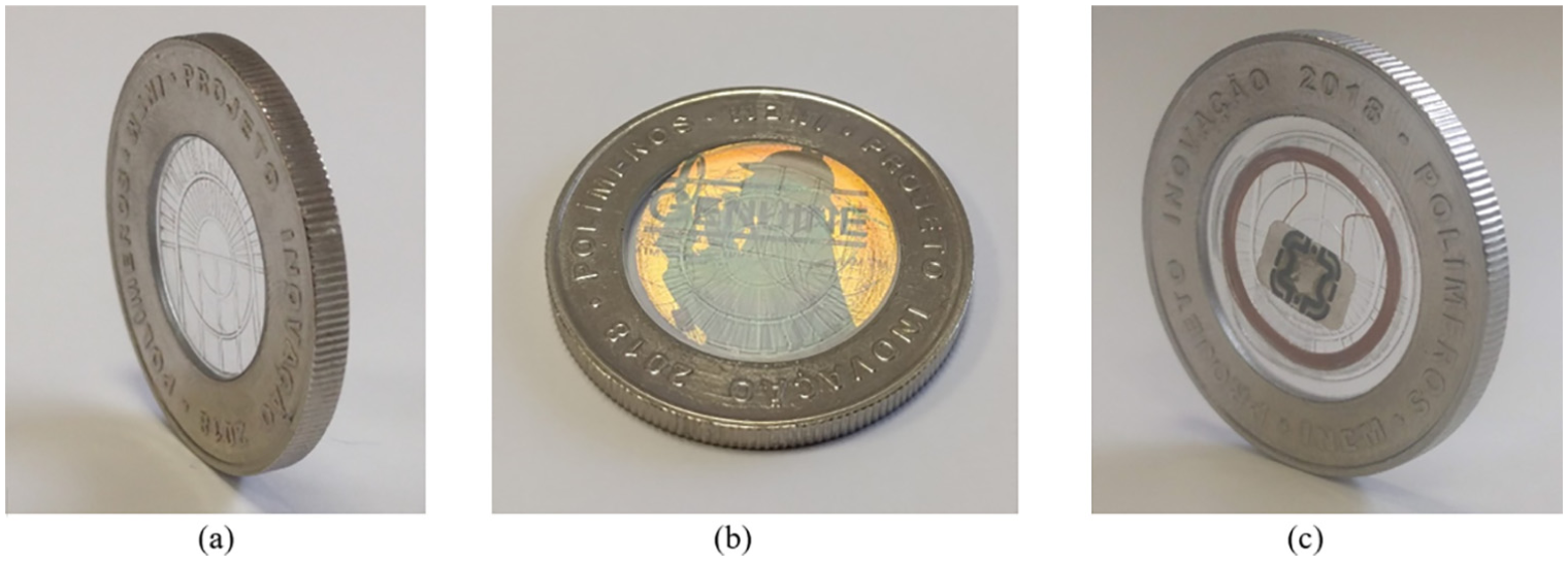
Prototypes of the new bi-material coin concept: (a) transparent polymer centre with reliefs for producing new aesthetic solutions, (b) polymer centre with holographic image for advanced security and (c) polymer centre with an embedded RFID device for advanced security.
By changing the colour of the polymer centre from transparent to coloured translucid and/or by including holographic images in laminated polymers like on Figure 13(b), it is possible to generate new aesthetic effects in collection coins.
In addition to the aesthetic effects, the polymer-metal coin prototypes of Figure 13(b) and (c) also include advanced security features for high-denomination collection coins. Figure 13(b) contains a holographic image within the layers of the laminated polymer, whereas Figure 13(c) discloses the idea of utilizing a polymer centre with an embedded RFID (radio-frequency identification) device.
All the test coins were successfully produced using the design methodology that was explained in the article.
Conclusion
This article presents a new bi-material polymer-metal coin with a large area ratio between the polymer centre and the outer metal ring and high reliefs imparted on the surfaces of the polymer. The polymer centre and the outer metal ring are locked together during coin minting by interface contact pressure resulting from radial interference between the two parts.
The interference depends on the initial clearance and initial thicknesses between the polymer centre and metal ring, and the initial clearance between the outer metal ring and the collar. An analytical model is proposed for estimating the interference and the resulting interface contact pressure as a function of the above-mentioned geometric parameters. The absence of interference leads to separation of the two parts after coin minting while large interferences give rise to instability and buckling of the polymer centre.
From a manufacturing point of view, the optimum design conditions correspond to the utilization of a clearance
Experimental test cases confirm the effectiveness of the analytical model for designing the new type of coin and for predicting the maximum force that is needed to push the centre out of the ring. Prototype bi-material polymer-metal coins fabricated at the Portuguese state mint validated the overall concept in real industrial conditions.
Footnotes
Acknowledgements
The authors would also like to acknowledge the technical assistance of Elisabete Novais and Nuno Caetano and the support of Dr Silvia Garcia and Dr Alcides Gama from INCM.
Declaration of conflicting interests
The author(s) declared no potential conflicts of interest with respect to the research, authorship and/or publication of this article.
Funding
The author(s) disclosed receipt of the following financial support for the research, authorship, and/or publication of this article: The authors would like to acknowledge the support provided by the Portuguese Mint (INCM – Imprensa Nacional Casa da Moeda) and IDMEC under LAETA-UID/EMS/50022/2013.