
Abstract
The coined-bead technique is an effective approach for controlling the spring-back characteristics involved in sheet-metal bending. Most previous studies have focused on the application of the coined-bead punch. In this application, bead marks are commonly formed on the inner radii of the bent components. To ensure the precision of the inner bent radius, a coined-bead die can be employed. However, information and data pertaining to coined-bead die applications are currently lacking. In the present research, the influences of the coined-bead die on the spring-back characteristics during V-die bending are investigated for aluminium alloy sheets (AA1100-O), by using the finite element method (FEM) and related physical experiments. Based on material flow and stress distribution analyses, it is found that the bending mechanism of coined-bead die application (particularly in the coining stage) is different from that of coined-bead punch application. Moreover, an increase in the punch radius-to-workpiece thickness ratio and decreases in the bend angle and coined-bead width result in increased spring-back characteristics. It is revealed that the coined-bead die can be applied to prevent spring-back characteristics and the bead mark at the inner radius. However, it was also noted that the V-shape parameters should be carefully considered for coined-bead applications. In addition, it is recommended that the width of the coined-bead die should be larger than that of the coined-bead punch.
Introduction
In recent years, there has been an increased demand for bent sheet-metal parts with complex shapes and precise dimensions. Such bent sheet-metal parts are applied in almost all industrial fields, such as for automotive, aerospace and electronics applications. However, the primary obstacle in improving the quality and precision of bent sheet-metal parts is the spring-back characteristics of the material. In the past,1–8 studies have focused on difficult-to-bend high-performance materials, including their bending mechanisms and the effects of process parameters on spring-back characteristics; similar studies have also aimed at improving the precision of bend angles in these sheet-metal parts. Furthermore, the spring-back characteristics of materials such as titanium alloy sheets,9,10 high-performance steel, including high-strength low-alloy sheets11–13 and stainless steel sheets, 14 and lightweight metal alloys, including aluminium alloy sheets15–17 have been investigated.
Based on the bending theory and previous research,18–22 an effective technique for controlling spring-back characteristics is the application of a coined bead. This technique involves creating a bead on a tool, pressing it onto the workpiece and forming a bead mark. 18 Based on the bending theory, 18 this bead mark eliminates a certain amount of bending stress generated on the bending allowance zone and generates compressive stress. Consequently, some portions of the elastic band, which is the main factor resulting in spring-back characteristics, are eliminated, and the spring-back characteristics can be prevented.
The coined-bead punch is a commonly applied tool. In recent years, the bending mechanism associated with the application of the coined-bead punch has been clarified.19,20 In contrast with the bending theory, application of the coined-bead punch eliminates certain amounts of bending stress generated in the bending allowance zone and generates compressive stress. In addition, it continues to generate reversed bending stresses on the legs of bent parts. Specifically, the decrease in spring-back characteristics is attributed to two factors: the decreases in bending stress in the bending allowance zone and the increase in reversed bending stress on the legs of the bent parts. Some studies have focused on using the coined-bead method to prevent spring-back characteristics. A sided coined-bead punch technique was proposed for the V-bending process, 21 while a centred coined-bead punch technique was proposed for the U-bending process. 22
However, studies focusing on the application of the coined-bead die have not been carried out. The current lack of research pertaining to this topic has hindered the applicability of the coined-bead die application technique in sheet-metal bending processes. Moreover, when using this coined-bead punch method, bead marks are created on the inner bend radius of the material. To avoid this, a better understanding of coined-bead die application is essential for preventing the creation of bead marks and achieving more precise inner bend radii in the bent parts. In this regard, the present study investigates the influences of the coined-bead die on spring-back characteristics using the finite element method (FEM) and related experiments. V-die bending, a simple bending process used to fabricate various types of differently shaped parts, is used as the bending model in this study. First, comparisons of the bending mechanisms and spring-back characteristics for applications of the coined-bead punch and the coined-bead die are analysed. Thereafter, influences of the V-shape parameters, including the bend angle and the bend radius-to-thickness ratio, and the coined bead sizes on the spring-back characteristics are examined.
This study reveals that the coined-bead die can be applied to prevent spring-back characteristics and the bead mark in the inner bend radius of the material. Moreover, the results suggest that the V-shape parameters should be carefully considered for coined-bead applications. The results of this study are expected to be considerably useful for improving the quality of V-bent parts by controlling their spring-back characteristics and obtaining precise inner bend radii without bead marks. Based on the current results and observations, future studies should investigate the feasibility of applying the coined-bead die technique to various die bending processes in order to improve the quality of the bent parts.
FEM simulation and experimental procedure
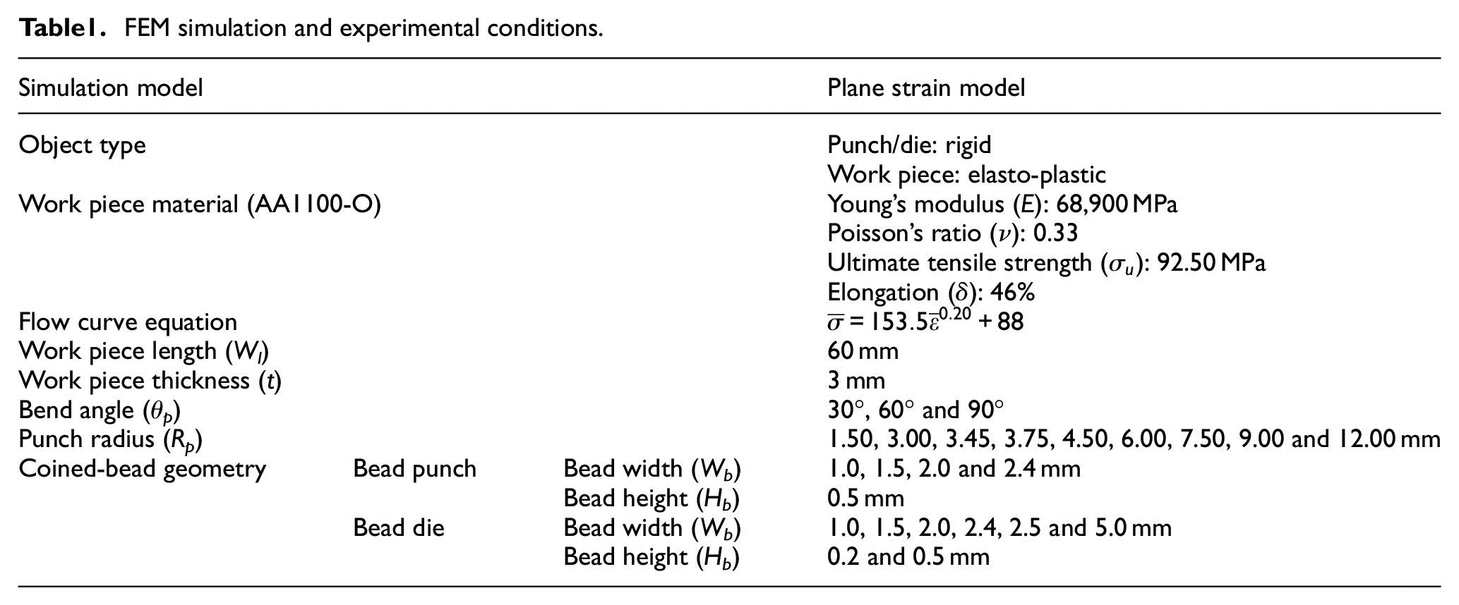
In the present research, to clarify the bending mechanism on applying the coined-bead die, the bending mechanism associated with coined-bead punch application is also investigated. The studied V-die bending models with and without coined-bead application are shown in Figure 1. The bending mechanisms were evaluated for bend angles of 30°–90° and various punch radius-to-thickness ratios, as listed in Table 1. The ratio of punch radius to the workpiece thickness was varied by setting the workpiece thickness to 3 mm and varying the punch radius from 1.5 to 12.0 mm. Next, as per previous research,19,20 owing to the wide range of punch radii and workpiece thicknesses examined in this study, typically recommended coined-bead sizes are used, as listed in Table 1. Based on,19,20 a two-dimensional plane strain model is employed, and the two-dimensional implicit quasi-static FEM commercial analysis software, DEFORM-2D, is used for FEM simulations. The solution algorithm utilised in the FEM model is based on the Newton–Raphson iteration. As listed in Table 1, the punch and die are set as rigid, and the workpiece material is set as elasto-plastic, with approximately 3500 rectangular elements. In addition, the adaptive remeshing technique, set every three steps, is applied to prevent divergence due to excessive deformation of the elements. As per previous research,19–23 based on the contact surface model defined by the Coulomb friction law, a friction coefficient (µ) of 0.10 is applied. As shown in Table 1, an aluminium alloy sheet AA1100-O (JIS) is used as the workpiece, and its properties are obtained from tensile testing data. An elasto-plastic, power-exponent isotropic hardening model was used, and the constitutive equation was determined from the stress–strain curve. The remaining material properties, including the Young modulus, Poisson’s ratio, elongation and the ultimate tensile strength, are presented in Table 1, along with the process parameters adopted. During the V-die bending process, deformation occurs in three stages: air bending, bottoming and coining. In general, spring-back characteristics are observed immediately before unloading commences. The bending stroke at which the gap between the punch and the die is equal to the workpiece thickness is calculated; this bending stroke is considered as the end of the coining stage and also the start of the unloading stage. During the coining stage, the bending force increases sharply, and compressive stresses are generated in the bent portions. Thus, the initial unloading stage is set considering the steep increase in bending force. At this stage, the observed bending stroke was in good agreement with that determined via calculations.
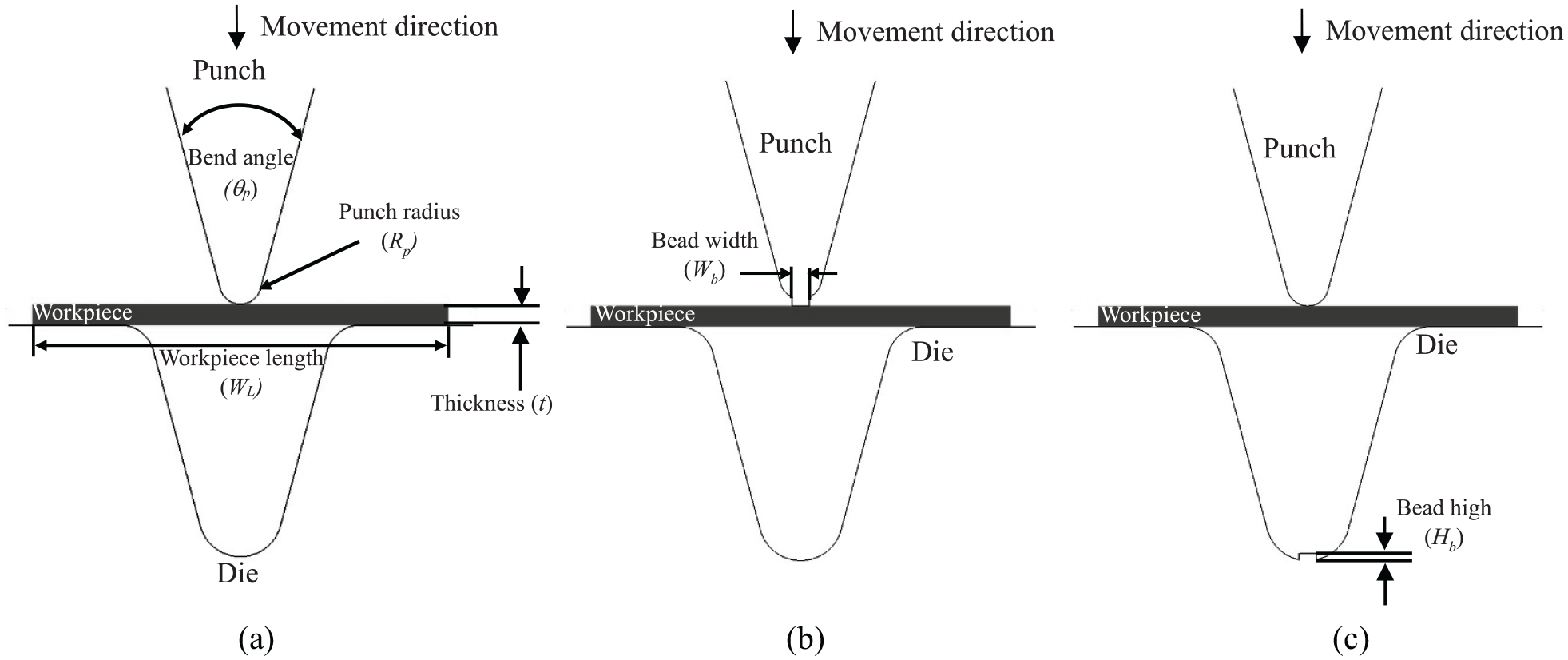
FEM simulation models of V-bending process: (a) no coined bead, (b) coined-bead punch and (c) coined-bead die.
FEM simulation and experimental conditions.
Laboratory experiments were performed to validate the FEM simulation results. In accordance with previous studies,19–21 Figure 2 shows the press machine, which includes a five-tonne universal testing machine (Lloyd Instruments Ltd., UK), and the cases of no coined bead, coined-bead punch and coined-bead die. Based on the bending load calculated during the bending phase, the initial unloading stage is set, where the sharp increase in bending load commences. In the experiments, the bend angle after unloading was measured using a profile projector (model PJ-A3000, Mitutoyo Corporation, Japan). Five samples from each bending condition were used to inspect the obtained bend angles. The amount of spring-back was calculated based on these bend angles and the average spring-back values as well as their standard deviations (SDs) are reported.
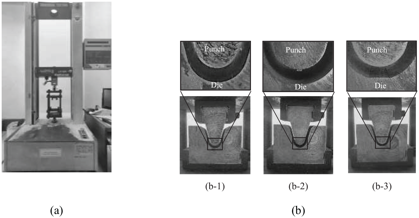
Press machine and die sets: (a) press machine and (b) die set, (b-1) no coined bead, (b-2) coined-bead punch and (b-3) coined-bead die.
Results and discussion
Validation of FEM simulations
FEM simulations are used as a tool for characterising the bending mechanism of coined-bead application and for predicting the obtained bend angle. Therefore, the accuracy of the FEM simulation results must be validated before obtaining the numerical results. Based on the obtained bend angle after unloading, the validation of the FEM simulation results was performed through a comparison with the experimental results. The experimental bent samples and their bend angles when applying no coined bead, coined-bead punch and coined-bead die are shown in Figure 3. Under the same bending conditions, the FEM simulation results are compared with the experimental results. The FEM simulation results indicate the formation of the spring-back and spring-go characteristics in the cases of no coined bead and coined-bead applications, which correspond favourably with the experimental results, with an error of approximately 1%. Additional the bending conditions were also investigated, as shown in Figure 4. Based on the five samples analysed, the average measured bend angles are reported, with a standard deviation of approximately 0.2°. The FEM simulation results show that the predicted bend angles correspond well with the experimental results, where the errors in the analysed bend angle are approximately 1% compared with the experimental results.
Comparison of bend angles obtained via FEM simulations and experiments (θ p : 30°, Rp: 3.45 mm, t: 3 mm and Rp/t: 1.15).
Bend angles obtained via FEM simulations and experiments (θ p : 30°, Rp: 3.45, 7.50 mm, t: 3 mm, Wb: 1.5, 5.0, 2.4 mm, Hb: 0.2, 0.5 mm): (a) no coined bead, (b) coined-bead punch and (c) coined-bead die.
Comparison of bending mechanisms with and without coined-bead application
As the mean stress can simultaneously exhibit compressive and tensile distributions in the bent parts, in the present research, mean stress was used to interpret the FEM simulation results. Owing to this advantage of using the mean stress, the spring-back/spring-go formations can be understood more easily. On the basis of material flow and stress distribution analyses, Figure 5 shows a comparison of the bending mechanism with and without coined-bead application. First, during the initial bending stroke, the workpiece was pushed by the punch and moved downward into the die, resulting in a bending moment over the punch radius, as shown in Figure 5(a). Similar bending mechanisms can be observed both with and without coined-bead application. Specifically, the material flow analyses show that the entire workpiece moves downward into the die at approximately the same velocity as the punch. This type of material flow is in good agreement with the bending theory and previously reported observations.20,21,24 When the coined bead was not applied, as shown in Figure 5(b-1), the material flow and stress distribution were similar to those in the previous bending stroke. The results show that, after the workpiece came in contact with the punch, the material was pushed into die, forming an S-curve. This material flow distribution corresponds well with that reported in literature. 24 Furthermore, when applying the coined-bead punch, as shown in Figure 5(b-2), the material underneath the coined-bead is pressed directly into the die and develops compressive stresses. However, some of the material also flowed upward against the punch direction, as observed in the legs. According to previous research,19,21 under this material characteristic, the overbending exceeds that when no coined bead is applied. However, as shown in Figure 5(b-3), for coined-bead die application, the material underneath the punch tip is forced on the coined-bead and compressive stress is generated. At this stage, the pressed material develops compressive stresses, forcing it to flow into the gap near the coined-bead die. Therefore, unlike the material flow when the coined-bead punch was applied, there was insufficient material to move upward along the legs; in this case, the material in the legs moved downward, that is, towards the die. Before the unloading stage, as shown in Figure 5(c) and in accordance with previous research, 24 the legs were in complete contact with the sides of the punch and the die; moreover, the legs were slightly compressed by the punch and die when no coined bead was applied, as shown in Figure 5(c-1). Owing to the formed S-curve material flow characteristic, reversed bending stress is generated in the legs. After compensating the stress generated at the bend radius and legs of the entire workpiece and unloading the punch, the material on the die opened slightly, with a spring-back of 1.67°, as shown in Figure 5(d-1). As shown in Figure 5(c-2), for coined-bead punch application, the entire workpiece is in complete contact with the sides of the punch and die. It was observed that the material at the bend radius moved upward along the legs and that the material flow in the legs was directed towards the side of the die. In terms of stress distribution, the bending stress generated at the bend radius zone was eliminated by the bead mark, which generated a compressive stress at the bead mark. In comparison with the case where the coined bead was not applied, the larger S-curve material flow resulted in a greater reversed bending stress in the legs. According to literature,19–24 the remaining stress in the bend radius zone results in a slight opening at the side of the die. In contrast, the reversed bending stress generated in the legs resulted in slight closing at the side of the punch. After compensating these stress distributions at the bend radius and legs for the entire workpiece, the material is slightly closed at the side of the punch, with a spring-go of 0.80°, as shown in Figure 5(d-2). Finally, for the coined-bead die application, as shown in Figure 5(c-3), the material flow generated reversed bending stress in the legs, which was less than that for coined-bead punch application. It was also observed that the generated reversed bending stress in the legs was identical to that when the coined bead was not applied. After compensating these stress distributions generated on the bend radius and legs of the entire workpiece, the material slightly opened at the punch side with a spring-back of 0.19°, as shown in Figure 5(d-3). As mentioned previously, it was first revealed that the mechanism of coined-bead die application, especially for the coining stage, was contrary to that of coined-bead punch application. In coined-bead punch application, the spring-back characteristics were controlled by decreasing the bending stress in the bend radius zone and increasing the reversed bending stress in the legs; this is in good agreement with the bending theory and literature.19–21 However, for coined-bead die application, the spring-back characteristics were only controlled by decreasing the bending stress in the bend radius zone; increasing the reversed bending stress in the legs had a negligible effect on the spring-back characteristics.
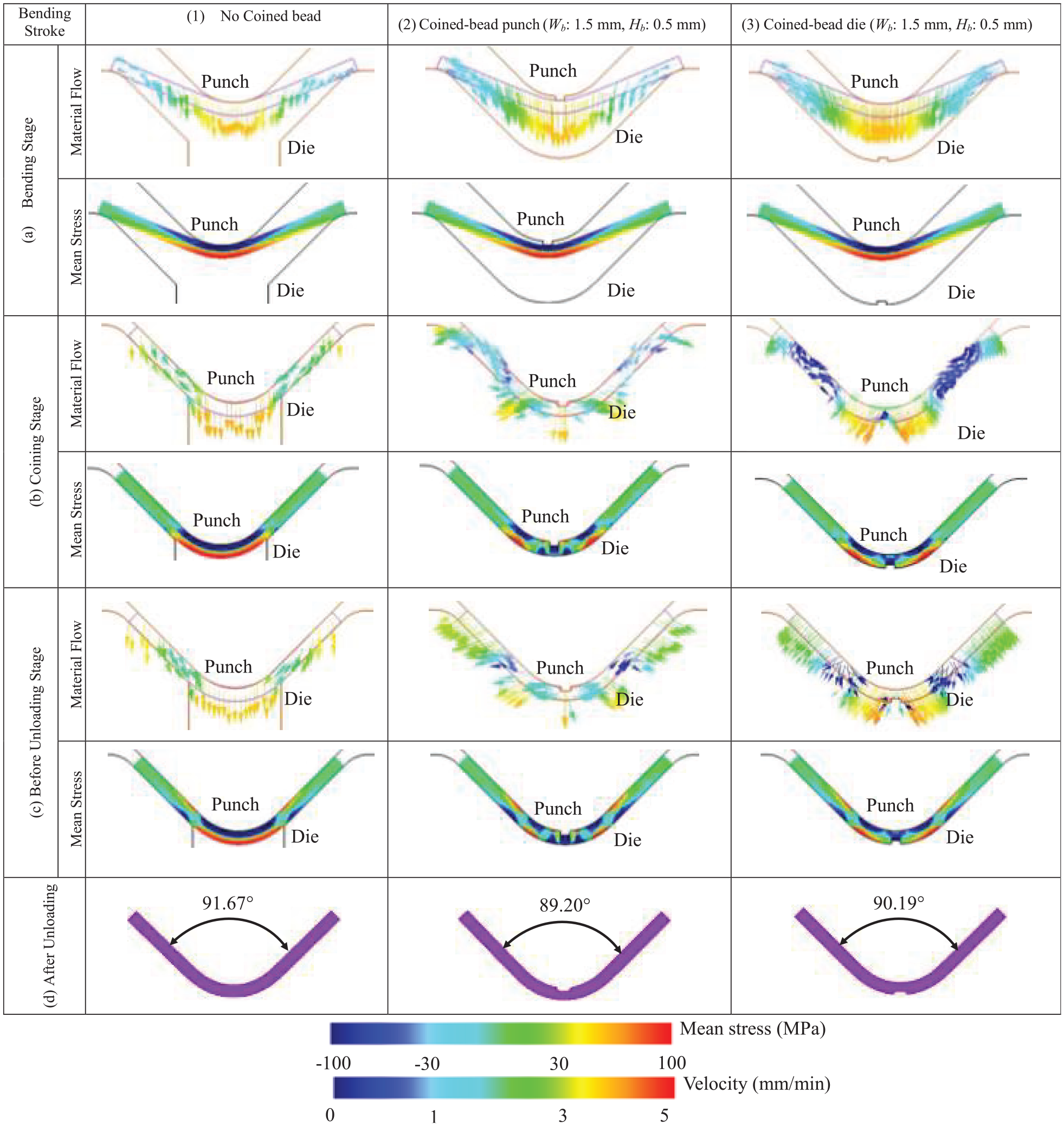
Comparison of material flows and stress distribution analyses during bending (θ p : 90°, Rp: 12 mm, t: 3 mm and Rp/t: 4):(a) bending stage, (b) coining stage, (c) before unloading stage and (d) after unloading.
Bending mechanism and spring-back/spring-go characteristics relating to V-shape parameters
In the present study, the relationship between the bending mechanism and the V-shape parameters, including the bend angle, punch radius and workpiece thickness, was investigated. The punch radius and workpiece thickness were represented by the ratio of the punch radius to the workpiece thickness (Rp/t). Before the coining stage, for both low and high punch radius-to-thickness ratios, identical material flows, stress distributions and contact zones between the workpiece and punch were noted, as shown in Figure 6(a). Specifically, the material in the bending allowance zone is moved downward to contact the die, and material in the legs is pushed backward to the die, forming an S-curve material flow, as shown in Figure 6(a-1) and (a-3). This material flow results in the generation of a bending stress in the bending allowance zone, as shown in Figure 6(a-2) and (a-4). It is noted that the punch is not in complete contact with the workpiece for both low and high punch radius-to-thickness ratios, as shown in Figure 6(a). Moreover, as the punch stroke increases, owing to the gap between the punch tip and the workpiece, the coined-bead die comes in contact with the workpiece and pushes the workpiece backward to once again come in contact with the punch tip. Thus, the pressed material is forced to flow into the gap near the coined-bead die for both low and high punch radius-to-thickness ratios, as shown in Figure 6(b-1) and (b-3), respectively. Specifically, during the coining stage, the material on the punch radius zone slightly opens on the die and makes more contact with the punch radius, as shown in Figure 6(b-1) and (b-3) for low and high punch radius-to-thickness ratios, respectively. At the end of the coining stage, the workpiece is in complete contact with the punch radius for a low punch radius-to-thickness ratio, as shown in Figure 6(b-1). However, a certain amount of contact between the workpiece and punch radius is generated for high punch radius-to-thickness ratios, as shown in Figure 6(b-3). These contact zones show the region of the bending allowance zone, which is bent in the opposite direction by the coined-bead die. Specifically, for a low punch radius-to-thickness ratio, the bending allowance zone is completely bent in the opposite direction; it slightly opens and comes in contact with the die. Therefore, the role of the stress generated in the bending allowance zone is converted from that of bending stress to that of reversed bending stress, although stress distribution analyses indicate compressive and tensile stresses on the punch and die sides, respectively. As shown in Figure 6(d-1), after unloading, the material in the bending allowance zone maintains the bent shape by first slightly closing at the side of the punch. In addition, the reversed bending of the legs causes the material to close at punch. After compensating these generated stress distributions, the results indicate a spring-go of 0.43°, although the stress distribution analysis shows that compressive and tensile stresses are generated on the punch and die sides of the bending allowance zone, respectively, which exceed the corresponding stresses in the legs. These results indicate that, under this condition, the coined-bead die could not be applied for controlling the spring-back characteristics and for achieving the required bend angle. Based on these explanations, the results shown in Figure 4(c) for the case of coined-bead die application are clarified. For the case of a high punch radius-to-thickness ratio, as shown in Figure 6(c-4), as the workpiece is not in complete contact with the punch radius, the material in the bending allowance zone is not fully bent in the opposite direction by the coined-bead die. Specifically, only the contacted zone is bent in the opposite direction, and it slightly opens and comes in contact with the die. The role of stress generated in the contacted zone is converted from that of bending stress to that of reversed bending stress, although stress distribution analyses indicate the generation of compressive and tensile stresses on the punch and die sides, respectively. In contrast, the non-contacted zone is not bent in the opposite direction, and the generated compressive and tensile stresses on the punch and die sides, respectively, still play a role in the performance of bending stress. As shown in Figure 6(d-2), after unloading, in addition to the reversed bending characteristic in the legs, caused by the material close to the punch, the contacted zone maintains the bent shape by slightly closing at the punch side, but the non-contacted zone maintains its original flat shape by slightly opening on the die side. After compensating these generated stress distributions, as shown in Figure 6(d-2), the results indicate a spring-back of 0.19°. These results highlight that, under this condition, the coined-bead die could be applied for controlling the spring-back characteristic and achieving the required bend angle. Thus, the results reveal that application of the coined-bead die is dependent on the V-shape parameters.
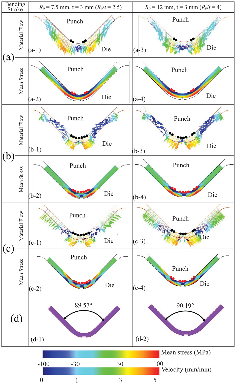
Comparison of material flows, stress distribution analyses and contact zones with respect to punch radius-to-workpiece thickness ratio (θ p : 90°, Wb: 1.5 mm, Hb: 0.5 mm):(a) before coining stage, (b) coining stage, (c) before unloading stage and (d) after unloading.
In terms of the bend angle, Figure 7 shows the contact between the punch and the workpiece with respect to the bend angles. Before the unloading stage, the workpiece does not make full contact with the punch radius under a small bend angle, as shown in Figure 7(a-1), but it makes full contact when a large bend angle is adopted, as shown in Figure 7(b-1). As mentioned previously, although a similar stress distribution is observed for both small and large bend angles, as shown in Figure 7(a-1) and (b-1), the generated stress in the bending allowance zone plays different roles. The generated stress of the contacted zone between the workpiece and the punch radius in the bending allowance zone acts as a reversed bending stress and maintains the bent shape by slightly closing at the punch side, resulting in a spring-go characteristic. In contrast, the generated stress of the non-contacted zone between the workpiece and the punch radius in the bending allowance zone acts as a bending stress and maintains the original flat shape by slightly opening at the die side, which results in a spring-back characteristic. For a small bend angle, after unloading, the stress distribution in the bending allowance zone and the legs was compensated, as shown in Figure 7(a-2). The results indicate a spring-back of 0.20°. In contrast, for a large bend angle, as shown in Figure 7(b-2), the results indicate a spring-go of 0.43°. In this study, the effects of V-shape parameters, including the workpiece thickness, the punch radius and the bend angle, on the spring-back characteristics were clarified. Under coined-bead die application, spring-back characteristics were controlled by decreasing the bending stress in the bending allowance zone; increasing the reversed bending stress in the legs had a negligible effect on the spring-back characteristics. However, the spring-back characteristics could not be controlled under a low punch radius-to-thickness ratio, because the role of bending stress in the bending allowance zone is converted to that of reversed bending stress. The spring-go characteristic was commonly generated when the coined-bead die was applied. In addition, the bend angle related to the punch radius-to-thickness ratio was also carefully considered.
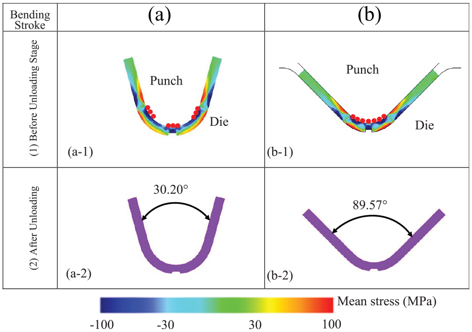
Comparison of stress distribution analyses and contact zones with respect to bend angles (Wb: 1.5 mm, Hb: 0.5 mm, Rp: 7.5 mm, t: 3 mm and Rp/t: 2.5): (a) bend angle = 30° and (b) bend angle = 90°.
Successful coined-bead die application with respect to V-shape parameters
Figure 8 shows the conditions under which coined-bead die application was successful, relative to the V-shape parameters. Region I corresponds to spring-go formation when the workpiece is bent without coined-bead application. As per previous research,19,20,24 considering V-die bending, bending stress is generated in the bending allowance zone. In addition, a reversed bending stress distribution is usually generated in the legs. Based on the V-shape parameters, after compensating these generated stress distributions for the entire workpiece, a spring-go formation is generated when the reversed bending stress exceeds the bending stress. In contrast, as shown in regions II and III, the spring-back formation is generated when the bending stress has more significant effects than the reversed bending stress. However, the results show that coined-bead die application for controlling spring-back characteristics may not be feasible under certain conditions, as shown in region II, because the role of bending stress in the bending allowance zone is converted to that of reversed bending stress, as mentioned above. Consequently, spring-go characteristics are noted for the bent parts. In addition, to clearly emphasise the effects of V-shape parameters, Figure 9 shows the spring-back/spring-go characteristics with respect to the bend angle, punch radius-to-thickness ratio and coined-bead die width. An increase in the punch radius-to-workpiece thickness ratio (by increasing the punch radius) results in a decrease in the contact zone between the workpiece and the punch radius in the bending allowance zone. As mentioned before, the generated bending stress in the bending allowance zone also acts as the reversed bending stress decrease. Therefore, the spring-back characteristics increase, or the spring-go characteristics decrease, as the punch radius-to-workpiece thickness increases. Furthermore, an increase in the bend angle increases the contact zone between the workpiece and the punch radius in the bending allowance zone, as previously mentioned. This also increases the reversed bending stress in the bending allowance zone. Therefore, spring-back characteristics decrease, or spring-go characteristics increase, as the bend angle increases. Although the results are not shown in Figure 9, for a 30° bend angle with Rp/t = 1.50, spring-back characteristics can be prevented by applying a coined-bead die with a width of 0.5 mm, and a spring-go of 0.13° can be obtained. Similarly, for a 60° bend angle with Rp/t = 2.00, spring-back characteristics can be prevented by applying a coined-bead die with a width of 0.5 mm, and a spring-go of 0.25° can be obtained. These results correspond well with the regions of successful coined-bead die application shown in Figure 8. Thus, V-shape parameters should be carefully considered when applying the coined-bead die to control spring-back characteristics.
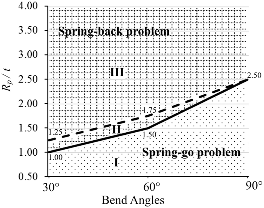
Illustration of the region of successful coined-bead die application (t: 3 mm).
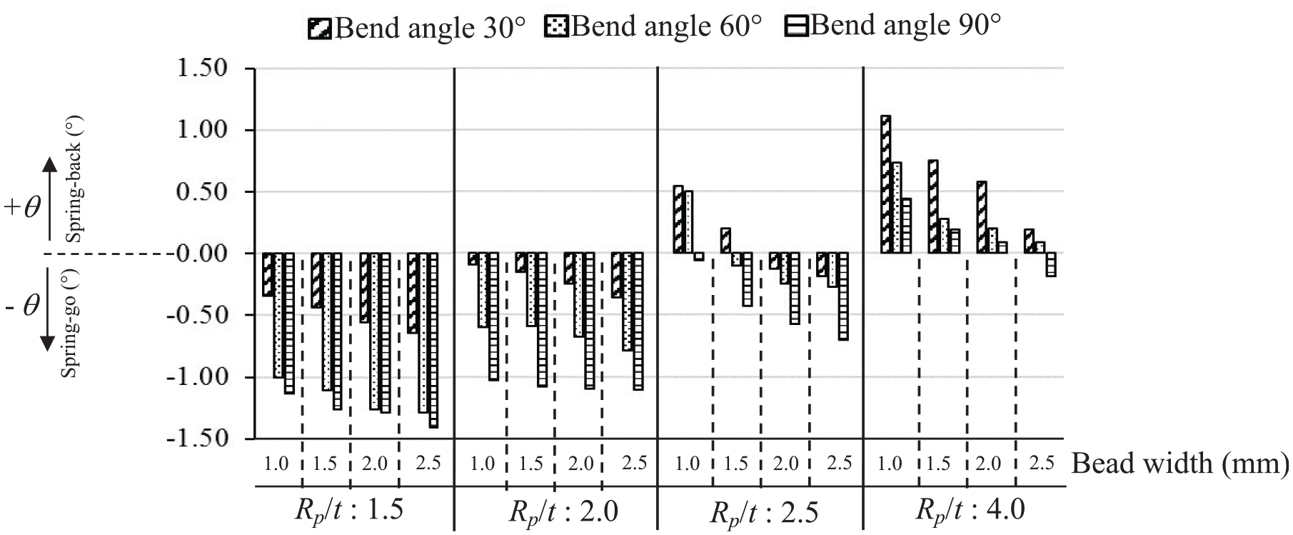
Relationship between spring-back/spring-go characteristics and V-shape parameters (t: 3 mm, Rp: 4.5, 6.0, 7.5, 12.0 mm and Hb: 0.5 mm).
Spring-back/spring-go characteristics with respect to coined-bead die widths
In this study, the effects of coined-bead die widths were investigated, in addition to the V-shape parameters. Figure 10 shows the stress distribution analysis before unloading and the obtained bend angle after unloading with respect to various coined-bead die widths. The results show that, as the coined-bead die width increases, the coined-bead mark and the eliminated bending stress increase, as shown in Figure 10(a-1), (b-1) and (c-1). After compensating these stress distributions, the results show that the spring-back characteristics decreases; therefore, the spring-go of the bent parts increases as the coined-bead die width increases, as shown in Figure 10(a-2), (b-2) and (c-2). The effects of coined-bead die width on the spring-back/spring-go characteristics are also reported in Figure 9. The results clearly show that spring-back characteristics decrease, or spring-go characteristics increase, as the coined-bead width increases, because of the decrease in the generated stress in the bending allowance zone. In addition, the width of the coined-bead die is also compared with that of the coined-bead punch, as shown in Figure 11. As previously mentioned, coined-bead die application only eliminates a certain amount of bending stress in the bending allowance zone, whereas coined-bead punch application eliminates a certain amount of bending stress in the bending allowance zone and increases the reversed bending stress in the legs. Therefore, to achieve the required bend angle, a larger coined-bead die width, as compared to the coined-bead punch width, is recommended, as shown in Figure 11. Specifically, to achieve a bend angle of 90°, a coined-bead punch with a width of 1.00 mm is recommended, whereas a coined-bead die with a width of 2.00 mm is recommended. In summary, the width of the coined-bead die should exceed that of the coined-bead punch, in order to achieve the required bend angle.
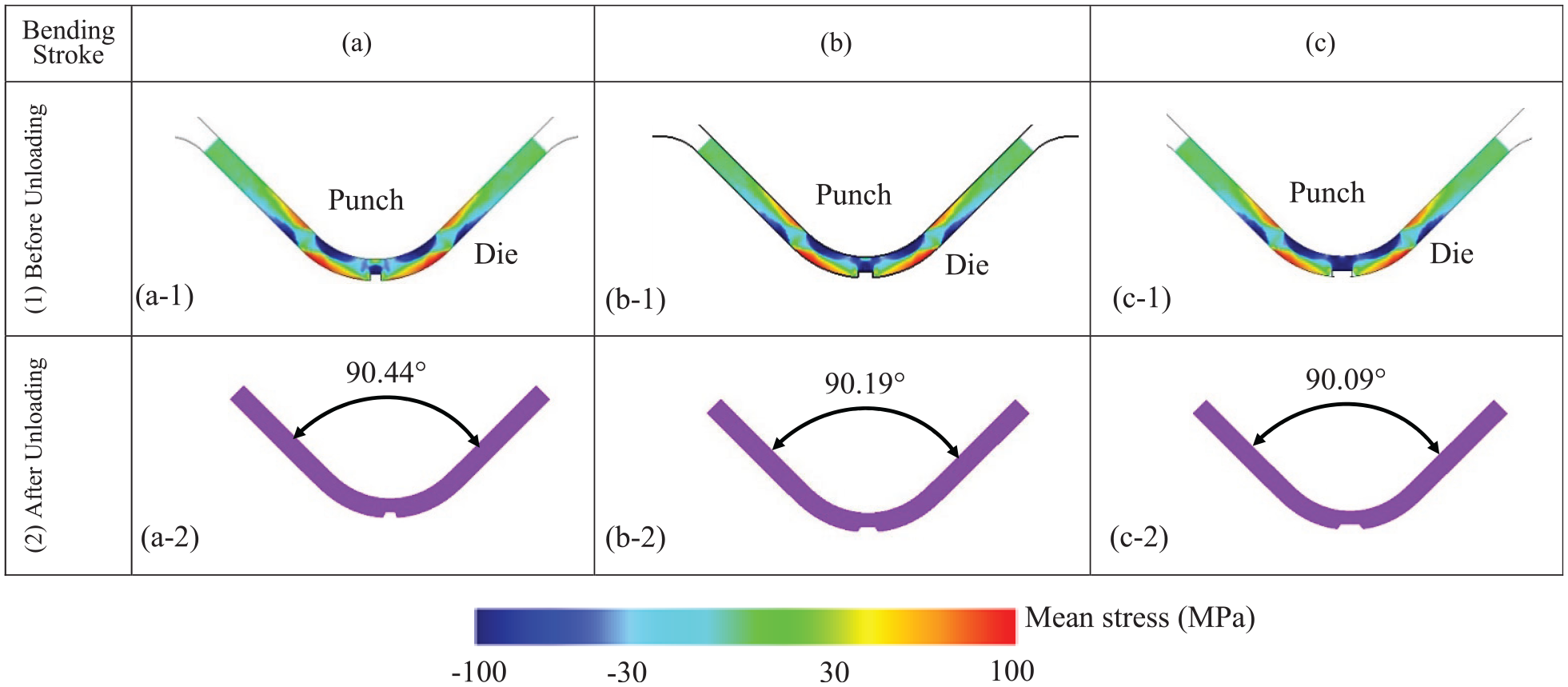
Comparison of stress distribution analyses with respect to coined-bead die widths (θ p : 90°, Hb: 0.5 mm, Rp: 12 mm, t: 3 mm and Rp/t: 4): (a) Wb = 1.0 mm, (b) Wb = 1.5 mm and (c) Wb = 2.0 mm.
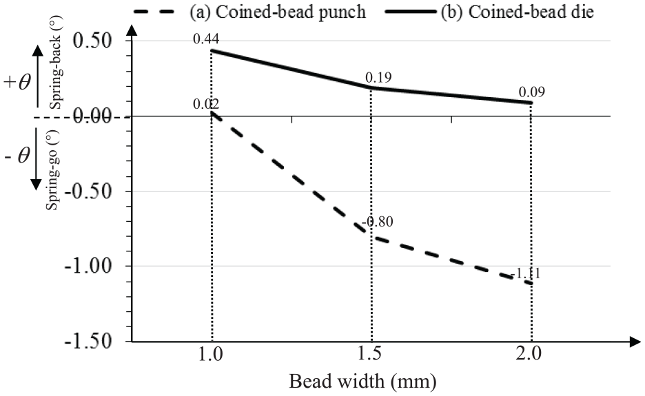
Comparison of spring-back/spring-go characteristics for the coined-bead punch and die applications (θ p : 90°, Hb: 0.5 mm, Rp: 12 mm, t: 3 mm and Rp/t: 4).
Validation of suggested coined-bead die application
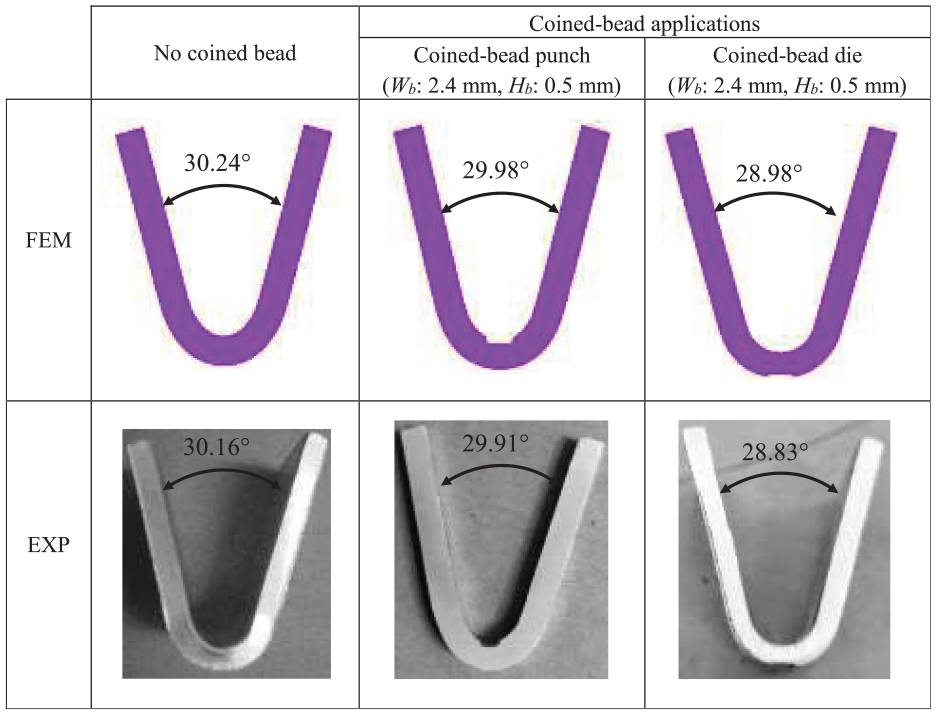
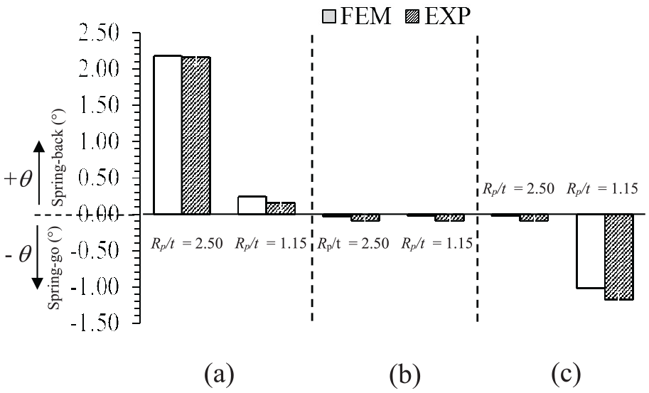
To confirm the accuracy of the suggested coined-bead die application, additional bending conditions were investigated using the suggested coined-bead die application. First, V-die bending without coined bead application was performed, and the amount of spring-back was analysed. Next, to achieve the required bend angle, V-die bending with coined-bead die and punch applications were performed. The results obtained via FEM simulations and the experiments were compared, as shown in Figure 12. The FEM simulation results show that the predicted bend angle corresponds well with that observed in the experiments, and the errors in the analysed bend angle were approximately 1% in comparison with the experimental results. The results show that, for a 30° bend angle with Rp/t = 2.50, the amount of spring-back is 2.18° when the coined bead is not applied, as shown in Figure 12(a). In the case of coined-bead punch and die applications, as shown in Figure 12(b) and (c), respectively, the results indicate that the application of the coined-bead can control spring-back characteristics and that the obtained bend angle is similar to the required bend angle. The results also indicate that the suggested coined-bead die applications are valid, that is, the coined-bead die applied to achieve the required bend angle was larger than the applied coined-bead punch. Specifically, the coined-bead punch had a width of 1.5 mm and height of 0.5 mm, whereas the coined-bead die had a width of 5.0 mm and a height of 0.2 mm, as shown in Figure 12(b) and (c), respectively. These results correspond well with the suggested coined-bead die application with respect to V-shape parameters. Thus, the coined-bead die can be applied to obtain the required bend angle. In addition to this, the V-shape parameters should be carefully considered. In addition, it was recommended that the coined-bead die should be larger than the coined-bead punch.
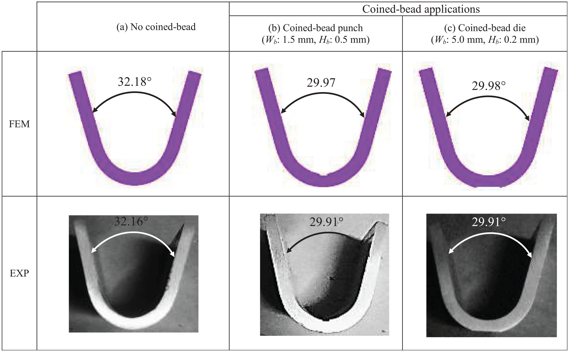
Comparison of bend angles for no coined bead, coined-bead punch and coined-bead die applications (θ p : 30°, Rp: 7.5 mm, t: 3 mm and Rp/t: 2.5): (a) no coined-bead, (b) coined-bead punch (Wb: 1.5 mm, Hb: 0.5 mm) and (c) coined-bead die (Wb: 5.0 mm, Hb: 0.2 mm).
Conclusions
In this study, using FEM simulations and related physical experiments, the bending mechanisms and spring-back characteristics during the application of the coined-bead die in V-die bending were investigated; the study aimed at using the coined-bead die for controlling the bend angle and for improving the precision of the inner bend radii. The results of this study can be summarised as follows:
The mechanism of application of the coined-bead die in the V-die bending process was clearly revealed. The application of the coined-bead die only served to eliminate a certain amount of bending stresses in the bending allowance zone, while barely increasing the reversed bending stress in the legs. This behaviour is contrary to that of coined-bead punch application.
This study suggests that the coined-bead die can be applied for the V-bending process. With regard to the V-shape parameters, when using the coined-bead die, the role of bending stress in the bending allowance zone was converted to that of reversed bending stress in the contact zone between the workpiece and the punch radius.
An increase in the punch radius-to-workpiece thickness ratio and decreases in the bend angle and the coined-bead width resulted in increased spring-back characteristic. To achieve the required bend angle, it is recommended that the width of the coined-bead die should be larger than that of the coined-bead punch.
Footnotes
Acknowledgements
The authors would especially like to thank Miss Wiriyakorn Phanitwong, PhD, Department of Industrial Engineering, Rajamangala University of Technology Rattanakosin for her help in this research.
Author contributions
Sutasn Thipprakmas: conceptualization, data curation, formal analysis, funding acquisition, investigation, methodology, validation, visualization, writing – original draft. Arkarapon Sontamino: investigation.
Declaration of conflicting interests
The author(s) declared no potential conflicts of interest with respect to the research, authorship, and/or publication of this article.
Funding
The author(s) disclosed receipt of the following financial support for the research, authorship, and/or publication of this article: This study was funded by The Thailand Research Fund (TRF) and King Mongkut’s University of Technology Thonburi (Grant No. RSA6180047).
Availability of data and materials
The raw and processed data required to reproduce these results are available by contacting the authors.