
Abstract
The stability of electrical discharge machining process would be improved by better expelling debris from machining gap. In this investigation, a rotational external magnetic field was applied around machining gap of near-dry electrical discharge machining process to make a new hybrid method for machining of stiff and high-strength parts. The Taguchi method of design of experiments was employed to study the effects of applying magnetic field in near-dry electrical discharge machining process. The experimental results showed that in magnetic field–assisted near-dry electrical discharge machining, material removal rate is more and surface roughness is less than in near-dry electrical discharge machining process without magnetic field, but tool wear rate is a little more. Also, the optical micrographs of the surfaces machined indicated better surface integrity resulted by magnetic field–assisted near-dry electrical discharge machining as compared to near-dry electrical discharge machining process without magnetic field.
Keywords
Introduction
In near-dry electrical discharge machining (EDM) process, a tube-shaped tool is used, and the dielectric which is the mixture of a gas and a liquid at high speed is sprayed through the hole in the tool on the workpiece surface. 1 In magnetic field–assisted EDM process, a magnetic field is applied on machining gap, and machining process is done under this condition. In this process, the machining performance is improved by applying magnetic force on molten droplets and increasing the movement of electrons and ionization in the plasma channel. 2 Using magnetic force to improve the performance of manufacturing techniques has been developed by many researchers recently,3–10 although these researches focused on using magnetic abrasive particles to finish the machined surfaces and introduced this method as a surface finishing process mainly, but some another researchers have used magnetic force to improve machining performance in machining process and especially in EDM process. Kao et al. 1 studied wire EDM cutting and EDM drilling under the wet, dry and near-dry conditions. Their results showed that near-dry EDM process has some advantages in comparison with dry EDM such as higher material removal rate (MRR), sharper cutting edge and less debris deposition, and in comparison with wet EDM, near-dry EDM has higher MRR at low discharge energy and generates a smaller gap distance. On the other hand, near-dry EDM creates a higher thermal load on the tool, which can break the wire in wire EDM and increase tool wear rate (TWR) in EDM drilling. They also developed a mathematical model to correlate the dielectric strength and viscosity to the gap distance. Jia et al. 11 investigated the near-dry EDM milling of Stellite alloys. They showed the discharge peak current has the most effect on machining performance, and by increasing discharge peak current, the MRR and surface roughness (SR) increase and TWR decreases. Tao et al. 12 in their investigation about dry and near-dry EDM milling indicated that near-dry EDM has good machining stability and surface finish under low discharge energy input. They investigated the effects of input parameters on MRR and SR in dry and near-dry EDM. Tao et al. 13 studied near-dry EDM milling process and investigated the effects of dielectric fluid, electrode material and pulse energy on MRR and SR. Fujiki et al. 14 investigated the effects of electrode lead and tilt angles and dielectric fluid flow rate on MRR, TWR and SR in near-dry EDM milling process. They also developed computational fluid dynamics (CFD) model to predict the dielectric fluid flow rate. Boopathi and Sivakumar 15 in their investigation about near-dry wire EDM process studied the effects of input parameters on MRR and SR and compared the performance of different dielectrics. Fujiki et al. 16 established a new gap control strategy for five-axis near-dry EDM milling and showed that MRR is increased by 30% by applying this strategy. Lin and Lee 17 investigated the machining characteristics of magnetic force–assisted EDM. They selected peak current and pulse duration to determine the effects of applying magnetic field on MRR, TWR and SR in EDM process. They also used scanning electron microscope (SEM) to study the magnetic force–assisted EDM process. Their results showed that machining performance are improved by this approach. Joshi et al. 2 applied a pulsating magnetic field tangential to the electric field in dry EDM process to improve process performance. Their results showed the improvement in surface quality and geometric accuracy by this approach. They also reported that magnetic field–assisted dry EDM has more MRR and zero TWR as compared to dry EDM process without magnetic field. Lin et al. 18 investigated the effects of magnetic force on EDM machining characteristics. They used Taguchi method to design a series of experiments. Their result showed that magnetic field–assisted EDM has more MRR, lower relative electrode wear ratio (REWR) and smaller SR as compared to conventional EDM. They also observed better surface integrity obtained by magnetic field–assisted EDM. Tomura and Kunieda 19 developed a two-dimensional finite element program to analyze the mechanism of the electromagnetic force applied to the wire electrode in wire EDM. They also analyzed the distributions of current density and magnetic flux density and obtained the electromagnetic force applied to the wire resulted by pulse current. They also calculated the wire movement when just the electromagnetic force was applied to the wire and verified these results by experimental results. Lin and Lee 20 investigated magnetic field–assisted EDM process and used Taguchi method to conduct a series of experiments to optimize the machining parameters using gray relational analysis. They also determined the most important process parameters that affected the performance characteristics of magnetic force–assisted EDM by variance analysis. Teimouri and Baseri 21 studied TWR and workpiece overcut in EDM process with rotational external magnetic field and rotational electrode. Their results showed that TWR and overcut increased in magnetic field–assisted EDM as compared to conventional EDM. Teimouri and Baseri 22 investigated the effects of applying magnetic field on MRR, TWR, SR and overcut in dry EDM process. They also determined the best tool material and geometry by considering MRR. Their results indicated that MRR is increased and SR is decreased by this approach. They also developed a mathematical model to correlate a relationship between process input parameters and main output parameters. Teimouri and Baseri 23 investigated MRR and SR in EDM process with rotational external magnetic field and rotational electrode. They studied the influences of process parameters on MRR and SR. Their results indicated that applying a rotational magnetic field around the machining gap improves MRR and SR. They also developed a mathematical model to correlate the input parameters and output parameters. In this investigation, the MRR, TWR and SR of magnetic field–assisted near-dry EDM and near-dry EDM process without magnetic field were compared to investigate the influence of applying magnetic field in near-dry EDM process, and also, the integrity of machined surface was studied by micrographs obtained by optical microscopy.
Experiments
Experimental setup
The EDM machine used in this investigation was a Tehran Ekram 304H/60A die sinking electrical discharge machine with isopulse generator. The rotary system of electrode was provided by an electro motor and belt mechanism mounted on machine, while the level of rotational speed was controlled by LS600 inverter. Experimental setup is shown in Figure 1(a) and (b).
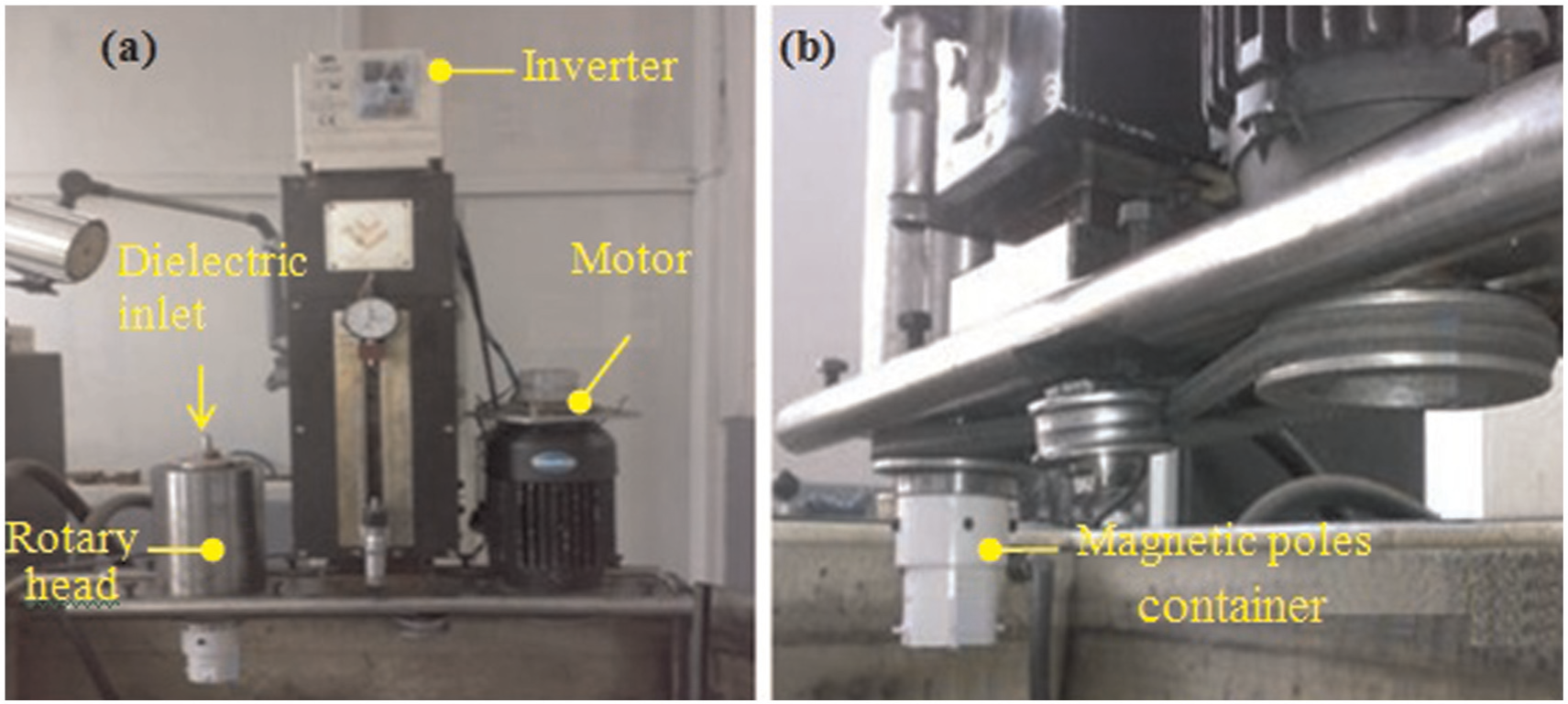
Experimental setup: (a) Tehran Ekram EDM machine and (b) mounted setup for rotation of electrode and magnetic poles container.
In order to establish a magnetic field around machining gap, a self-designed magnetic force–assisted system was attached to the EDM machine. This self-designed system has two magnetic poles with various intensities (0.38 and 1.2 T), which is attached on an inner surface of a cylinder with central through hole and would improve the removal of machining debris from machining gap. Figure 2 demonstrates the schematic diagram of magnetic container device and magnetic field lines and depicts the installation of rotary tool and tool holder on it and also the process of material removal mechanism. The magnetic poles encircle the workpiece by rotation of tool.
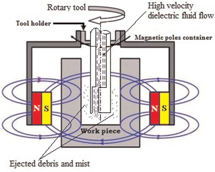
Magnetic poles container and magnetic field lines around workpiece showing the process of material removal mechanism.
In order to supply the liquid–gas mixture to the gap distance between workpiece and electrode, a new experimental setup was developed. The experimental setup of the near-dry EDM process is shown in Figure 3. It consists of a compressor, pump, fluid tank, biaxial hose, flow meter and the pressure gauge. The pressure gauge controls the gas pressure and flow meter controls the liquid flow rate. The two separate hoses (biaxial hose) of 10 and 4 mm diameter are used to pass the gas medium and liquid, respectively. The liquid and gas used in this investigation were water and air, respectively.

Experimental setup of the near-dry EDM process.
Experimental procedure
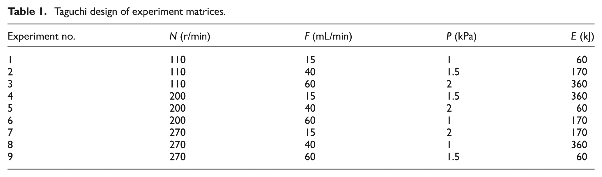
In this work, in order to assess the influence of applying magnetic field on near-dry EDM process, the Taguchi method of design of experiments technique is applied to conduct a series of experiments. The Taguchi design matrix is shown in Table 1. These experiments are done in both magnetic-assisted near-dry EDM and near-dry EDM process without magnetic field to extract the required information. Analysis of discharge waveforms is also used to study the effects of applying magnetic fields in near-dry EDM process. Also, the optical micrographs which were obtained from different positions of machined surface are used to compare the surface integrity of magnetic field–assisted near-dry EDM and near-dry EDM process without magnetic field.
Taguchi design of experiment matrices.
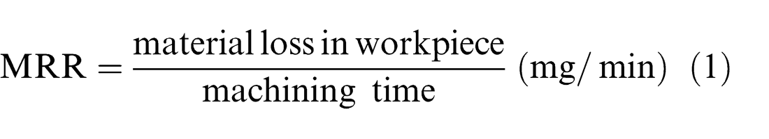
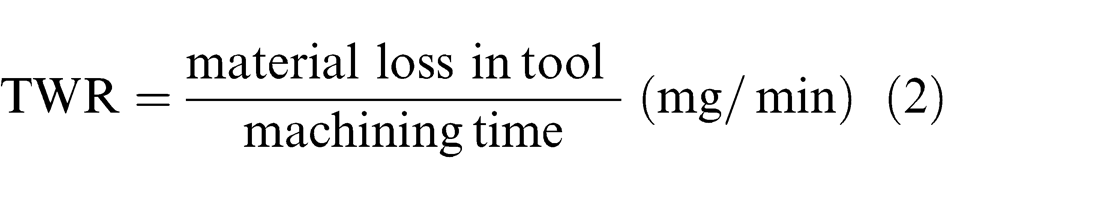
The WTB RADWAG electronic weigh balance with 1-mg resolution was used in order to evaluate the MRR and TWR. Each workpiece specimen and tool electrode was weighed before and after machining process. MRR and TWR were determined as follows
SR of the workpiece has been measured using the Mahr Marsurf PS1 surface profilometer with 0.8-mm cut-off length and 2-µm tip radius. The roughness of machined surface was measured five times conducted on different positions of the machined surface at each machining condition and the average of five stochastically measurements was known as value of SR.
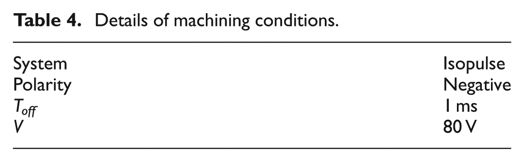
Three specimens have been tested for each kind of conditions to reduce the experimental error and increase the measurements accuracy, and the average value of these three measurements (Ave.) and their standard deviations (SDs) of magnetic field–assisted near-dry EDM process and near-dry EDM process without magnetic field are listed in Tables 2 and 3. The machining time was set at 35 min for all experiments. The details of machining conditions conducted in this investigation are given in Table 4.
Results of measurements in near-dry EDM process without magnetic field.
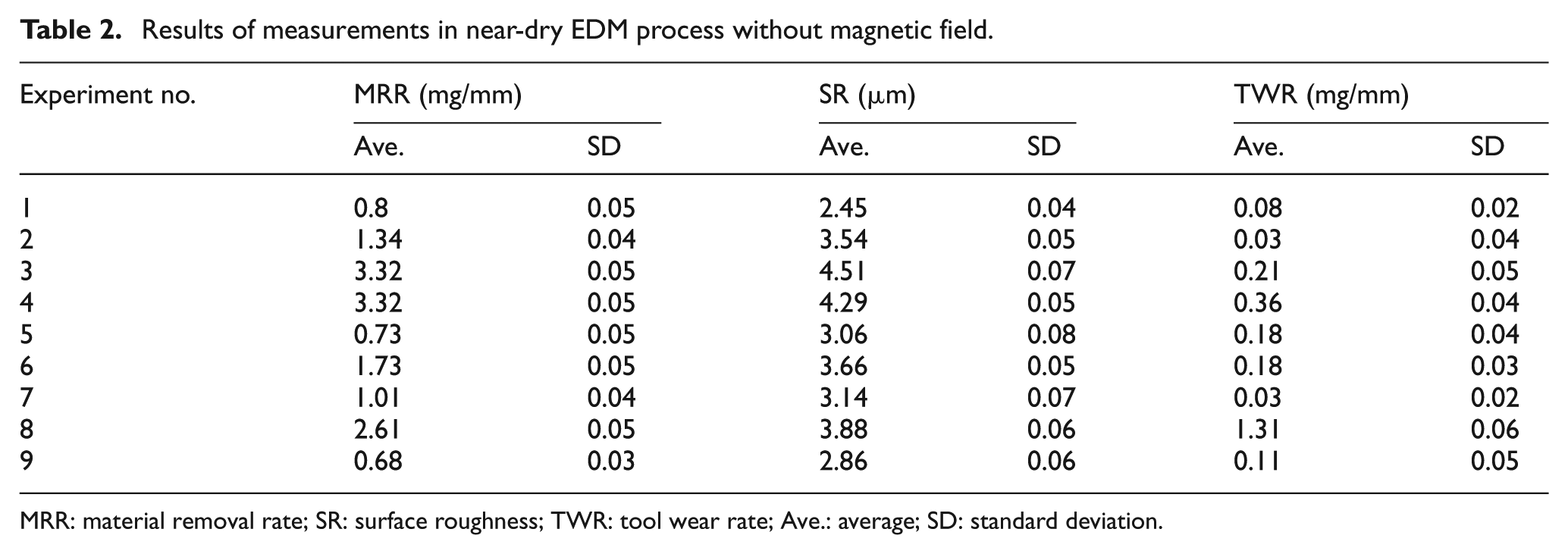
MRR: material removal rate; SR: surface roughness; TWR: tool wear rate; Ave.: average; SD: standard deviation.
Results of measurements in magnetic field–assisted near-dry EDM process.
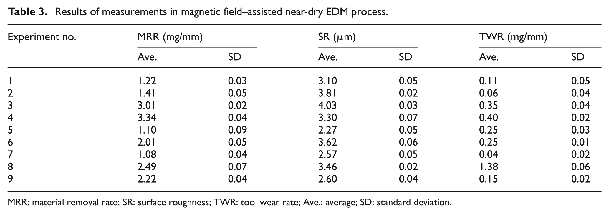
MRR: material removal rate; SR: surface roughness; TWR: tool wear rate; Ave.: average; SD: standard deviation.
Details of machining conditions.
Experimental materials
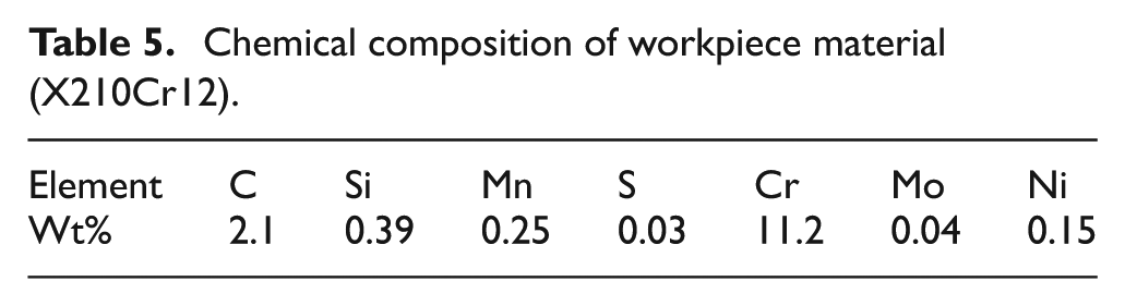
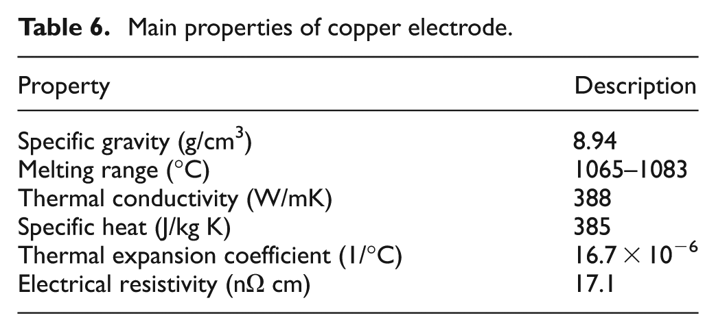
The workpiece material was 1.2080 X210Cr12 cold work steel, which is used extensively in dies and mold industry. The cylindrical specimen’s dimensions were 16 mm diameter and 25 mm height which was faced and ground. A copper tubular electrode which has one eccentric hole, with 99.9% purity and 10 mm outer diameter, 3 mm inner diameter and 50 mm height, was used in this investigation. Tables 5 and 6 list the chemical composition of 1.2080 X210Cr12 cold work steel and the main properties of copper electrode, respectively.
Chemical composition of workpiece material (X210Cr12).
Main properties of copper electrode.
Results and discussion
Effects of magnetic field on MRR
Figure 4 showed comparative main effect plots for MRR in magnetic field–assisted near-dry EDM and near-dry EDM process without magnetic field. As shown in Figure 4, the MRR obtained by magnetic force–assisted near-dry EDM is higher than that obtained by near-dry EDM without magnetic field in all cases. The maximum improvement of 60% and the minimum improvement of 30% were observed in comparison with corresponding experiment without using magnetic field.
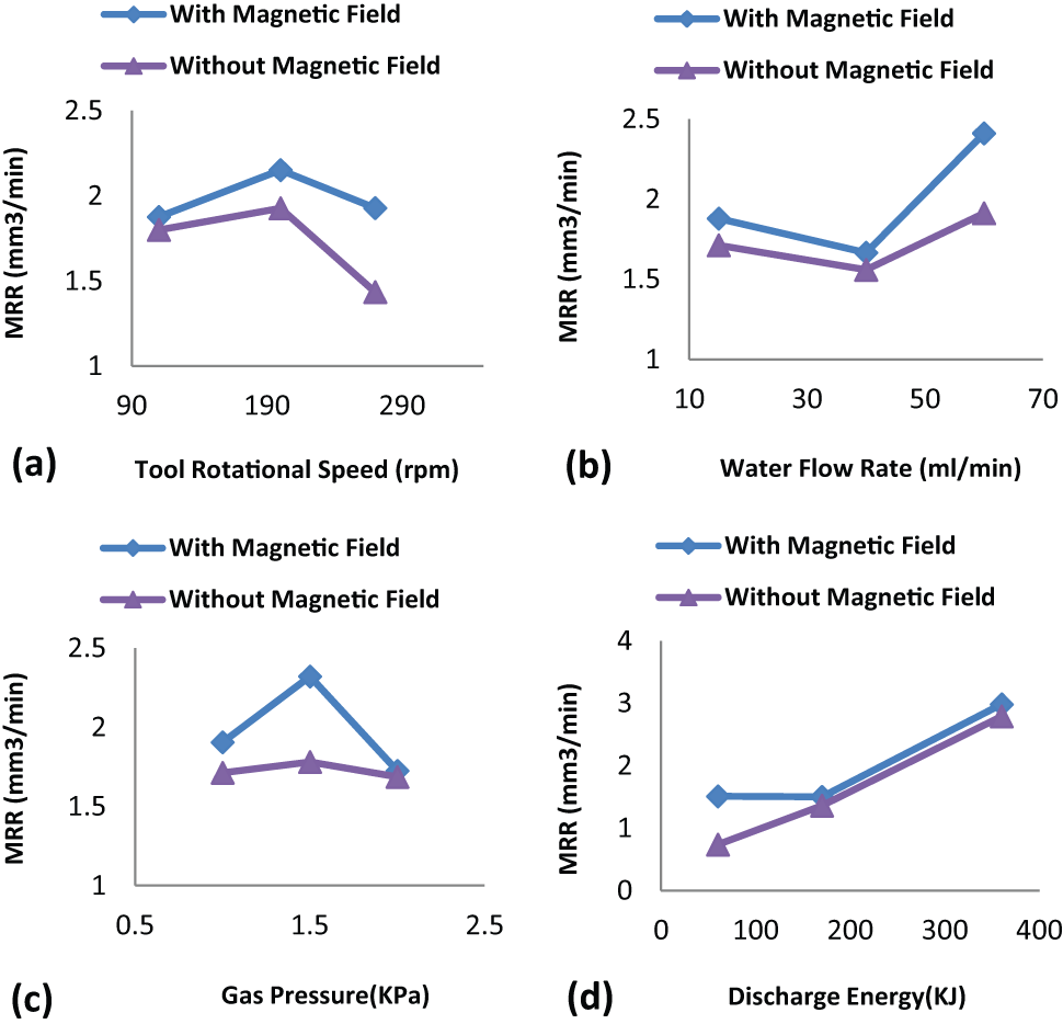
Main effect plots for MRR in magnetic-assisted near-dry EDM and near-dry EDM process without magnetic field.
Magnetic force can help the expelling of the eroded particle from machining gap, and so, the stability of process improves, and therefore, the machining efficiency and MRR are increased. Also, magnetic force can improve disengage of spinning electrons and ions from their atom’s cores and can increase ionization. On the other hand, due to the plasma channel consists of ions, so the formation of plasma channel is hastened by applying magnetic field around machining gap and therefore, ignition delay time reduces and MRR increases. In magnetic field–assisted near-dry EDM, the plasma pressure increases because the magnetic force acts tangential to the plasma and prevents its expansion, and so, the mean free path of ions decreases and as a result the density of plasma increases. Increasing density of plasma leads to more MRR. Also, an increase in plasma pressure and a decrease in the mean free path of the ions increase the number of ionization events (α) in gap distance given by
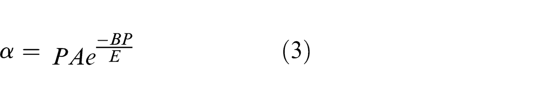
where A and B are constants for a particular gas, P is plasma pressure and E is the electric field in gap distance. Also, the collisions between particles in plasma channel increase due to applying magnetic field, and this helps ionization and faster breakdown of dielectric given by the breakdown criteria
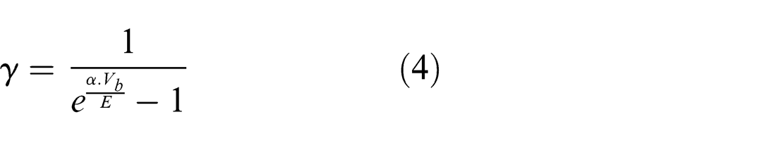
where γ is number of electrons emitted from cathode due to initial ionization and Vb is the breakdown voltage. As a result, electronic current density je and the energy (J) of the plasma increase as given by
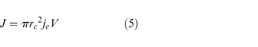
where rc is the radius of a micro-peak on cathode emitting electrons and V is the voltage across cathode and anode, and this leads to higher MRR.
Effects of magnetic field on SR
Comparative main effect plots of SR obtained by magnetic field–assisted near-dry EDM and near-dry EDM process without magnetic field are shown in Figure 5. Applying magnetic field on near-dry EDM process causes to improve the expelling machining debris away from machining gap; therefore, the probability of re-melting and sticking of debris on the machined surface and the generation of abnormal electrical discharge induced by accumulated debris would be less. Also, the machining debris which is expelled by magnetic force away can grind the rough edge of discharge craters generated on workpiece surface in their expulsion path, and so, SR is reduced by applying magnetic field on near-dry EDM process. The maximum improvement of 30% and the minimum improvement of 10% were observed in comparison with corresponding experiment without using magnetic field.
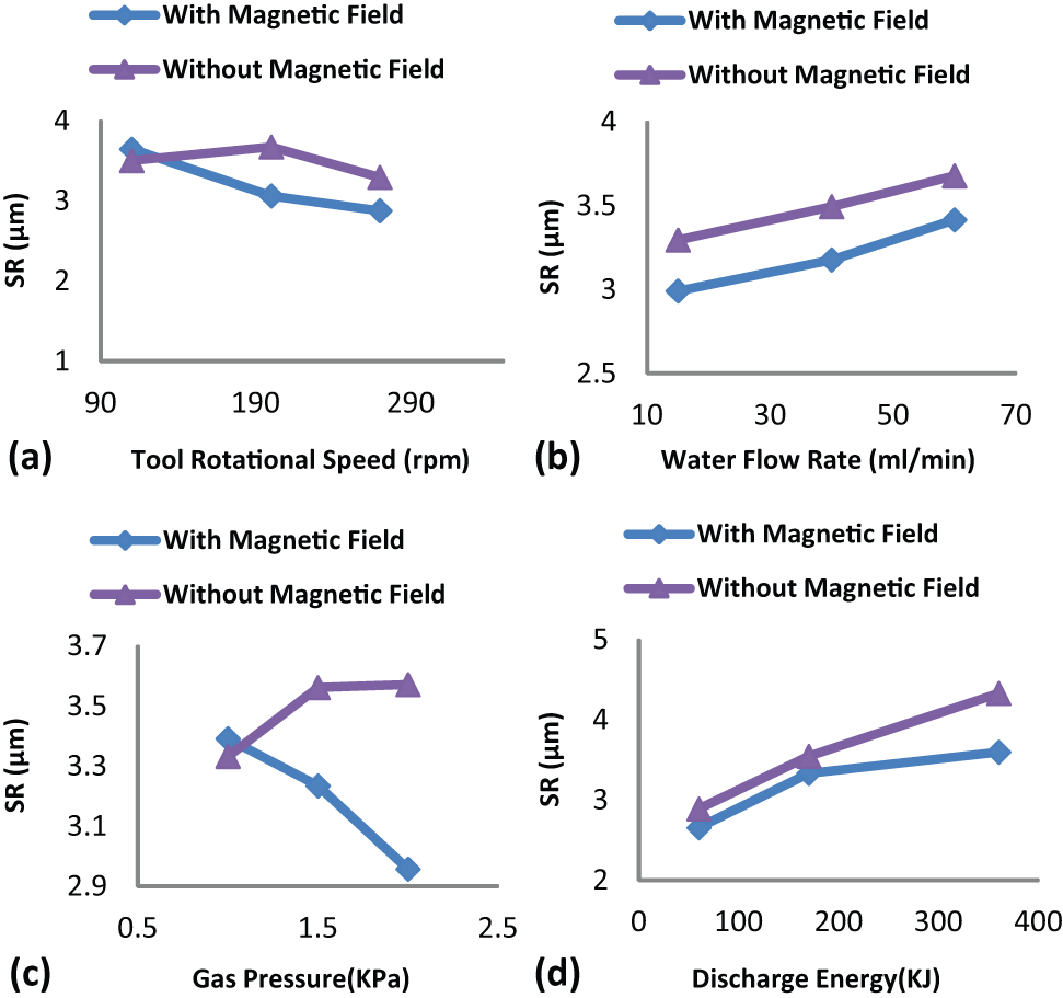
Main effect plots for SR in magnetic-assisted near-dry EDM and near-dry EDM process without magnetic field.
Effects of magnetic field on TWR
According to Figure 6, TWR obtained by magnetic field–assisted near-dry EDM is higher than that obtained by near-dry EDM process without magnetic field. TWR is enhanced by applying magnetic field because establishing of magnetic field helps the ionization at the start of discharge, and so, the ignition delay time is reduced and leads to increase in TWR. Also, the mechanism of chip removals in near-dry EDM process such as melting and vaporization in the machining zone not only removed the workpiece materials but also eroded the electrode materials, and as a result, the TWR is increased by applying magnetic field around machining gap because magnetic field improves these mechanisms. Also, the magnetic field expels the debris from machining gap and improves the process stability, and so, the number of inactive pulses is reduced, and therefore, the TWR is increased. Nevertheless, in magnetic field–assisted near-dry EDM, the anode (tool electrode) temperature is higher than that in near-dry EDM process without magnetic field, and the molten particles remain at higher temperature for longer duration, and so, the possibility of deposition of molten droplets on electrode is less; hence, there is less negative TWR. Reducing the negative TWR by applying magnetic field is a helpful factor and keeps the dimensional accuracy and uniformity of composition of tool electrode.
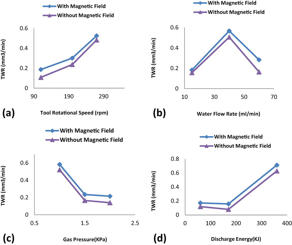
Main effect plots for TWR in magnetic-assisted near-dry EDM and near-dry EDM process without magnetic field.
Analysis of discharge waveforms
Analysis of the discharge waveforms has some benefit such as ability of monitoring of gap condition and determining the stability of near-dry EDM process. The comparison of discharge waveforms of magnetic force–assisted near-dry EDM and near-dry EDM process without magnetic field with 30 A peak current, 50 ms pulse duration, 200 r/min tool rotational speed, 40 mL/min flow rate and 1.5 kPa gas pressure at machining time of 10 min is demonstrated in Figure 7.
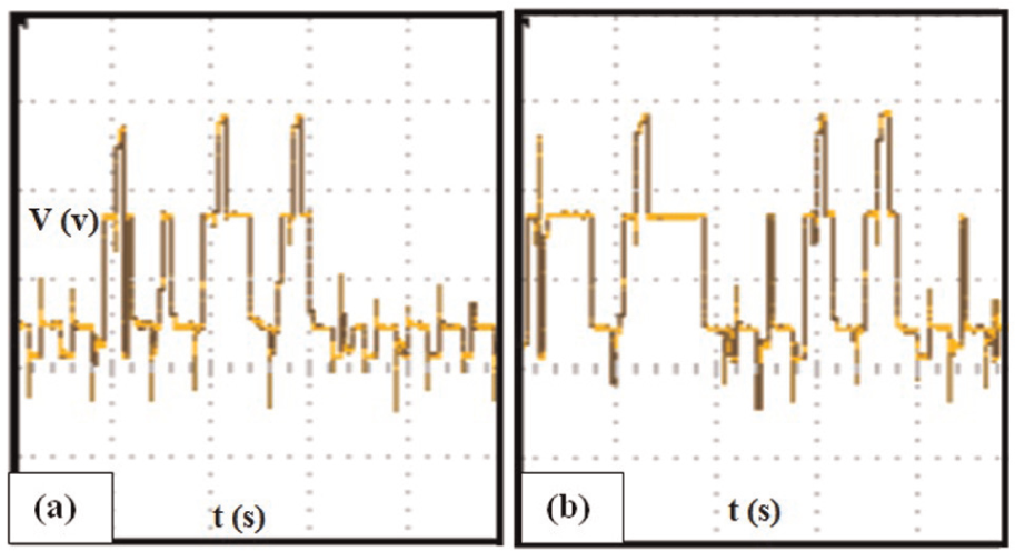
Discharge waveforms of (a) magnetic force–assisted near-dry EDM and (b) near-dry EDM process without magnetic field, after machining 10 min.
If the gap cleaning is not done efficiently, the machining debris is not removed from machining gap effectively, and the accumulated debris causes to generate the abnormal electrical discharge, and this kind of discharge have unfavorable effects on the machining characteristics.
As shown in Figure 7, the number of effective discharge waveforms obtained by the magnetic force–assisted near-dry EDM is more than that obtained by near-dry EDM process without magnetic field. In magnetic force–assisted near-dry EDM, due to the debris driven by magnetic force, machining debris would be expelled from machining gap more effectively, and therefore, the gap pollution and number of abnormal discharge are reduced according to Figure 7, and machining stability is enhanced, and as a result, machining efficiency is increased, and so, higher MRR and lower SR were obtained by magnetic force–assisted near-dry EDM although higher positive TWR was obtained by magnetic force–assisted near-dry EDM because of less abnormal pulses obtained by this condition, but as mentioned above, amount of negative TWR obtained by magnetic force–assisted near-dry EDM was less than that obtained by near-dry EDM without magnetic field.
Analysis of machined surface integrity
The machined surfaces which are obtained by magnetic field–assisted near-dry EDM and near-dry EDM process without magnetic field with 30 A peak current, 50 ms pulse duration, 200 r/min tool rotational speed, 40 mL/min flow rate and 1.5 kPa gas pressure at machining time of 10 min is shown in Figure 8. The white places in this figure are the debris which did not expel from machining gap and stuck on machined surface, and as shown in this figure, these places are more at near-dry EDM process as compared to magnetic-assisted near-dry EDM. According to this figure, the better machined surfaces are obtained by magnetic field–assisted near-dry EDM because applying magnetic field can improve debris flushing from machining gap, and so the possibility of sticking of debris on machined surface decreases, and also, the probability of occurring abnormal pulses like arc which can deteriorate the machined surface reduces, and surface integrity is improved.
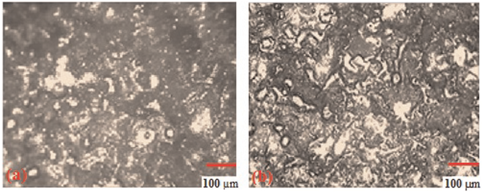
Optical micrographs of machined surface in (a) magnetic field–assisted near-dry EDM and (b) near-dry EDM process without magnetic field.
Conclusion
In this research, the effect of applying rotational magnetic field on MRR, TWR and SR was studied. Main conclusions of this investigation can be summarized as follows:
Applying magnetic field in near-dry EDM process, improved debris flushing from machining gap and reduced the number of abnormal pulses; therefore, the MRR obtained by magnetic field–assisted near-dry EDM process is higher than that obtained by near-dry EDM process without magnetic field in all cases.
By applying magnetic field at near-dry EDM process, machining debris expelled from machining gap more efficiently, and so, the possibility of re-melting and sticking of debris on machined surface is reduced, and therefore, SR is decreased in all experiments by applying magnetic field.
The electrode material erosion is increased by applying magnetic field in near-dry EDM process, and so, TWR is increased, but the amount of deposited removed workpiece materials on tool surface is decreased in magnetic-assisted near-dry EDM process.
Ability of applied magnetic field at debris flushing and reducing abnormal pulses causes that the analysis of discharge waveforms indicates more efficiency of magnetic field assisted near-dry EDM process.
The optical micrographs of machined surface showed better surface integrity in the case of magnetic field–assisted near-dry EDM.
Footnotes
Declaration of conflicting interests
The authors declare that there is no conflict of interest.
Funding
This research received no specific grant from any funding agency in the public, commercial or not-for-profit sectors.