
Abstract
In the present study machining performance of a novel ABS P400 based EDM electrode is experimentally investigated. Three EDM parameters that is, current (I), pulse on time (Ton) and pulse off time (Toff), each at three levels, are considered, and mild steel is machined using these electrodes according to the response surface methodology (RSM) based face-centred central composite design (FCCCD). Machining performances such as material removal rate (MRR), tool wear rate (TWR) and surface roughness (SR) are measured. Experimental results are analysed using analysis of variance (ANOVA), response graphs and 3D surface plots. Current is found to be the dominating parameter for MRR, TWR and SR. The optimal combination of EDM parameter for multi-performance is determined using teaching-learning based optimization (TLBO) algorithm. The effectiveness of the new electrodes is established by comparing their machining performances with the already developed electrode at the same machining parameter setting. MRR resulting from the new electrode and also its TWR are found to be in good agreement with those of already produced electrodes. However, SR of the machined surface using new electrodes is found to be relatively higher.
Introduction
Die-sinking electrical discharge machining (EDM) is a commonly used machining process for precise machining of titanium, tungsten, super alloys, composites and ceramics.1–4 In EDM, the electrode and the workpiece remain submerged in a dielectric fluid, and they are connected to the appropriate terminals of a power source. During machining, a series of repetitive sparks occurs between the electrode and the workpiece which melts the workpiece material causing its removal. 5 It has been found that in a mould and die industry1,6,7 EDM of the mould and die consumes around 25%–40% of the cycle time whereas, 50% of the cycle time is spent in electrode making 8 which ultimately increases both the machining time as well as the cost. The machining time and the cost are further increased when the required cavity to be machined is more complicated with minute details. 8 To react to such situations in less time and economical manner, the use of additive manufacturing (AM) techniques is an effective option. 9 AM can even machine customized and complex shapes on hard material with better workpiece surface characteristics.10,11 AM techniques used for electrode production can be categorized into two groups: one using conductive material like selective laser sintering (SLS) and the other using non-conductive materials such as fused deposition modelling (FDM). Use of AM for EDM electrode production using conductive material is more explored. EDM was successfully done to produce textured surfaces using tool electrode produced by selective laser melting (SLM). 12 SLM was also used for production of copper electrode to be used in EDM. 13 However, EDM electrodes of commonly used material that is, copper are difficult to be fabricated by SLS and SLM process due to high conductivity, reflective index and poor flow ability of copper. 9 Besides, porosity remains a major problem in electrodes fabricated by SLS due to which strength of the produced electrode is low.14,15 FDM produces electrode of acrylonitrile-butadiene-styrene (ABS) and to make it suitable for EDM application its metallization is done using well-established techniques reported in the literature.16–19 Hence, FDM has great potential for the production of EDM electrodes but is relatively less explored.8,9 To fulfil the EDM requirements, it is essential to make the FDM fabricated ABS electrodes conductive by depositing an adequate thickness of the conductive layer on them so that machining can be made possible without any interruption. It has been found that metallization of electrode produced by FDM has been done using electroless plating process followed by electroplating.8,9,18 Electroless plating is a slow process and also in this process, chromic acid is used as an etching agent which is toxic and thus, it makes the process non-environmentally friendly. Besides, careful handling of chromic acid is required to avoid any danger during etching. 18 A new method for metallization of the FDM fabricated ABS parts is required, which can reduce the electrode fabrication time and also address the environmental issues. To bridge this gap, authors got motivated to use a novel route for metallization of the ABS electrodes produced by the FDM so that they can be used as EDM electrodes. Consequently, a new metallization method comprising of the following sequential steps has been used: (i) For primary metallization, a coating of aluminium-charcoal (Al-C) paste was applied on the FDM fabricated ABS electrodes, and (ii) copper (Cu) electroplating of the electrodes to enhance coating thickness was done. The objectives of this study were as follows:
To produce ABS based electrodes using FDM followed by their metallization to make them suitable for EDM application in accordance with the process reported in the literature. 20
To evaluate machining performance of the new electrodes, in terms of MRR, TWR and SR, under the influence of three EDM parameters, each at three levels, using response surface methodology (RSM) based face centred central composite design (FCCCD).
To determine the optimal combination of the EDM parameters for optimum multi-performance using TLBO.
To establish effectiveness of the new EDM electrode by making a comparison between its performance and the performances of already developed electrodes reported in the literature that is, solid copper (SC) electrode and FDM fabricated electrode (FDM-EMR electrode) using recognized metallization route 8 under the same machining parameters setting.
The novelty of this paper is that it has evaluated the machining performance of a new ABS based EDM electrode which has been produced using FDM process and a novel metallization route of first providing Al-C paste on it and then doing its copper electroplating.
Methodology
Production of EDM electrode
EDM electrodes were produced as per the procedure available in the literature.
20
However, for the benefit of the readers and practitioners, the process is explained briefly as follows: ABS cylindrical electrodes were produced at optimal combination of the FDM process parameters. Compressive strength of the electrodes was measured to ensure that they possessed sufficient strength to withstand high compressive stresses produced at their inner core during machining.
21
Primary metallization of the electrodes was done using Al-C paste to induce the conductive particles in them and then required thickness of the coating was achieved using copper electroplating. During electroplating, current density (

Where, T is coating thickness in mm and t is the deposition time in h. Fabricated electrodes are shown in Figure 1.
Produced electrodes.
Experimental design and performance measures
To evaluate machining performances of the EDM electrodes, experiments were designed using a response surface methodology (RSM) 22 based face centred central composite design (FCCCD) as shown in Table 1. FCCCD considers three levels for each factor and fewer centres runs than other CCD designs. EDM parameters and their levels shown in Table 2 were selected from the literature. 8 It is to be mentioned that parameters and their levels shown in Table 2 were purposefully selected because the same machining parameters setting was used for evaluation of the machining performance of SC and FDM-EDM electrodes. On a Vidyunt (MMT, ZNC) EDM machine, machining using new electrodes was done as per the scheme shown in Table 1 and cavity of diameter 6.5 mm and depth 2 mm was produced in the mild steel workpiece.
RSM based FCCCD design.
EDM parameters and their levels. 8
Data for machining performance measures, namely material removal rate (MRR), tool wear rate (TWR) and surface roughness (SR) were collected by following the procedure given as under:
Material Removal rate (MRR): MRR (in g/min) was calculated using equation (2).
Where, Mi and Mf are the weight (in g) of the workpiece pre and post-machining, respectively which were measured using a weighing machine (Model: Mettler PM1200, Make: India) and t is the machining time (in min), which was recorded using stopwatch of the mobile phone.
Tool wear rate (TWR): TWR refers to the weight of the material that wears out of the electrode and it was calculated in g/min using equation (3).
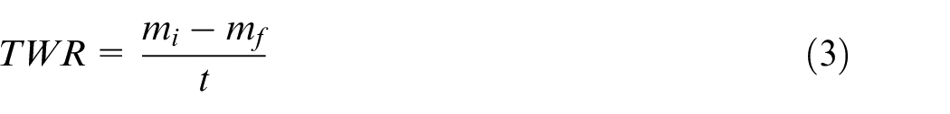
Where, mi and mf are the weight (in g) of the electrode pre and post-machining that were taken with the help of a weighing machine (Model: Mettler PM1200, Make: India) and t is machining time (in min) which was recorded using stopwatch of the mobile phone.
Surface roughness (SR): SR of the machined cavity was measured (in µm) using Hommel Werke Turbo Wave V7.20 roughness tester. The roughness was measured at six different locations of the cavity, and their average was taken.
Experimental results were analysed using analysis of variance (ANOVA).
23
ANOVA is a decision-making tool that is used to evaluate the effect of process parameters and their interactions on the output responses. The significance of the parameters and interactions is established using p-value. Parameters and interactions having p-value
Teaching learning based optimization (TLBO) algorithm
TLBO algorithm has been inspired by the behaviours of teachers and learners interacting in a classroom during teaching and learning process. Several engineering fields such as structural engineering, electrical engineering, production scheduling, quality control and control system24–26 have applied this optimization algorithm. Population-based optimization algorithms like genetic algorithm (GA) and differential evolution (DE) require proper tuning of parameters associated with the concerned algorithm. Inappropriate tuning of the parameters significantly affects the efficiency, and hence, appropriate selection of the specific parameters for these algorithms is the main problem.27,28 Like other algorithms, TLBO does not require any algorithm-specific parameter and also it is a relatively simpler, easier and effective optimization method. 29 It is an iterative algorithm resembling the teaching-learning process of a classroom where students improve their knowledge from teachers and other students.26,29
In a class of N students (population size) studying m subjects (number of decision variables), if zpq denotes the knowledge level of a student p in subject q (p = 1, 2, 3, …, N and q = 1, 2, 3, …, m), then the overall knowledge (yp) of a student depends on his/her knowledge in each subject that is, yp = f(zpq) for all q. The objective is to maximize the objective function, yp which represents the overall knowledge of the students. It may be noted that for maximization and minimization problems, the maximum and minimum values of the objective function signify maximum overall knowledge, respectively. In the teaching phase, the teacher interacts with the students to enhance their knowledge level. A student’s knowledge level in each subject after interaction with a teacher is determined by equation (4).

where,

Here, the teacher is identified as the student with the highest overall knowledge. It is assumed that the overall knowledge level of a student might deteriorate after interaction with the teacher. Hence, for each learner, the overall knowledge level corresponding to the best among yp = f(zpq) and ypnew = f(zpqnew) is considered, and the latter is rejected.
In the learning phase, students interact with each other to improve their knowledge level. This interaction can be either complete (a student interacts with every other learner) or partial (a student interacts with some other randomly selected students). The knowledge level of a student ‘U’ after interaction with a student ‘V’ is calculated using equations (6) and (7) according to the required objective functions value as either maximum or minimum, respectively.
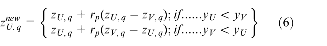
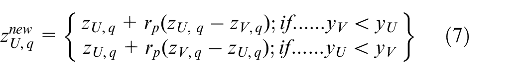
Where,
It is likely that improvement in the knowledge of a student might vary due to interaction with different students. Hence, a student’s knowledge level matching to the highest value of yp is considered as his/her final knowledge level. One iteration of the TLBO is completed subsequent to the overall knowledge level of learners after the teacher phase and learner phase taken together. The iterative process continues until the value of the objective function representing knowledge level of each learner becomes equal or attains a desired level.
Results and discussions
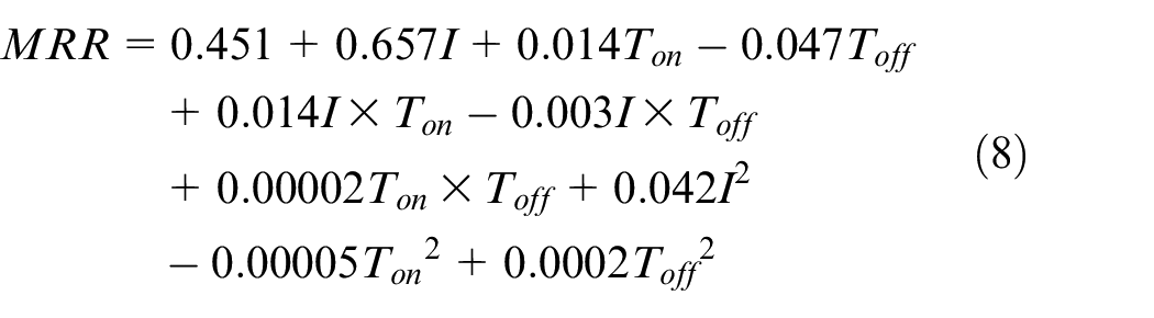
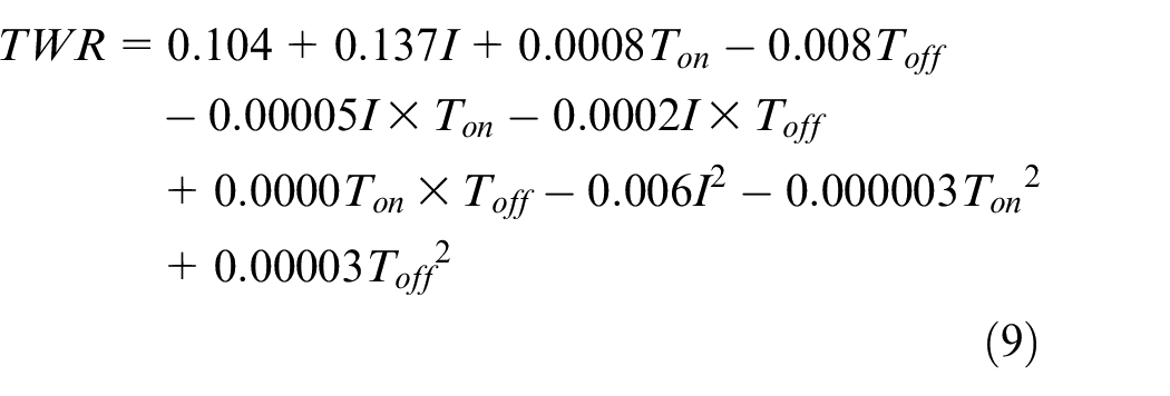
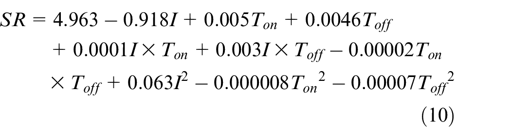
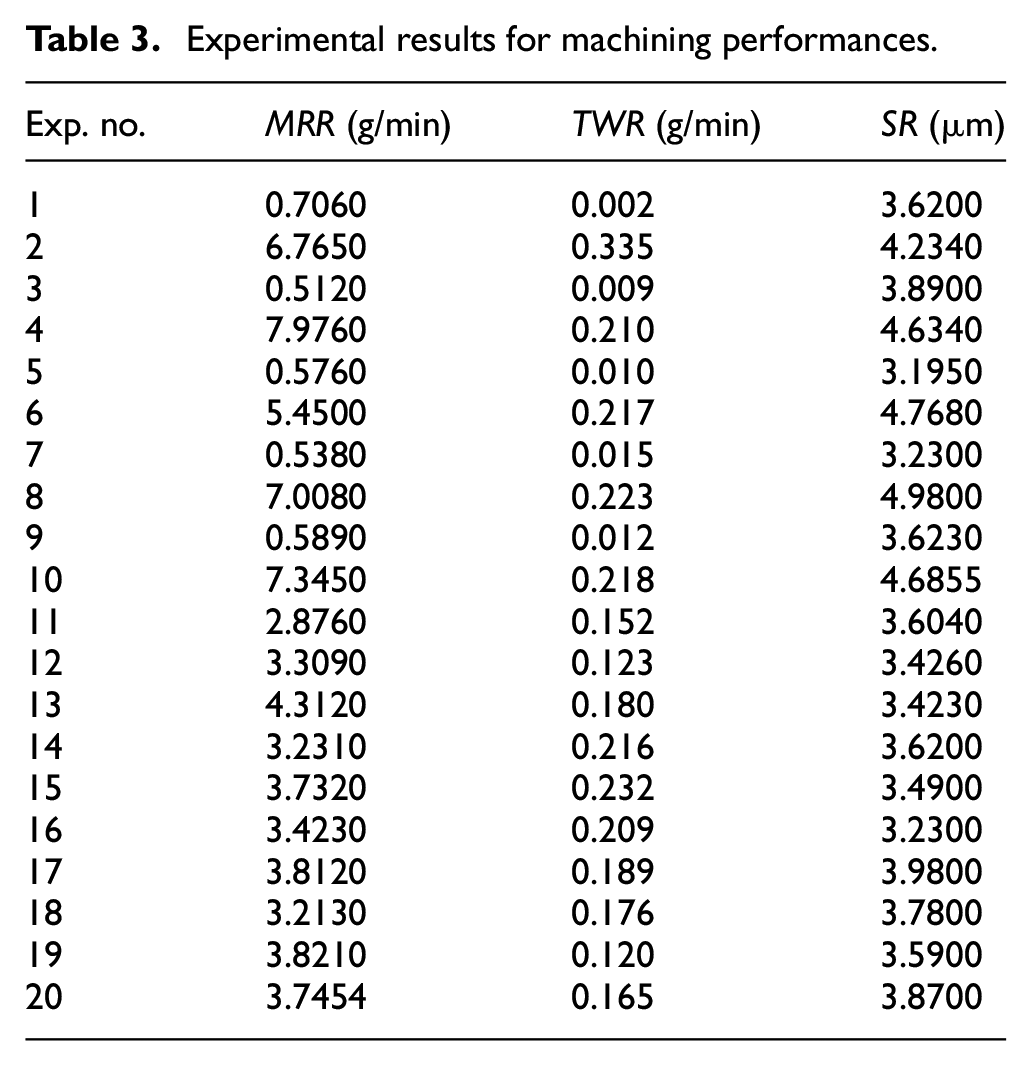
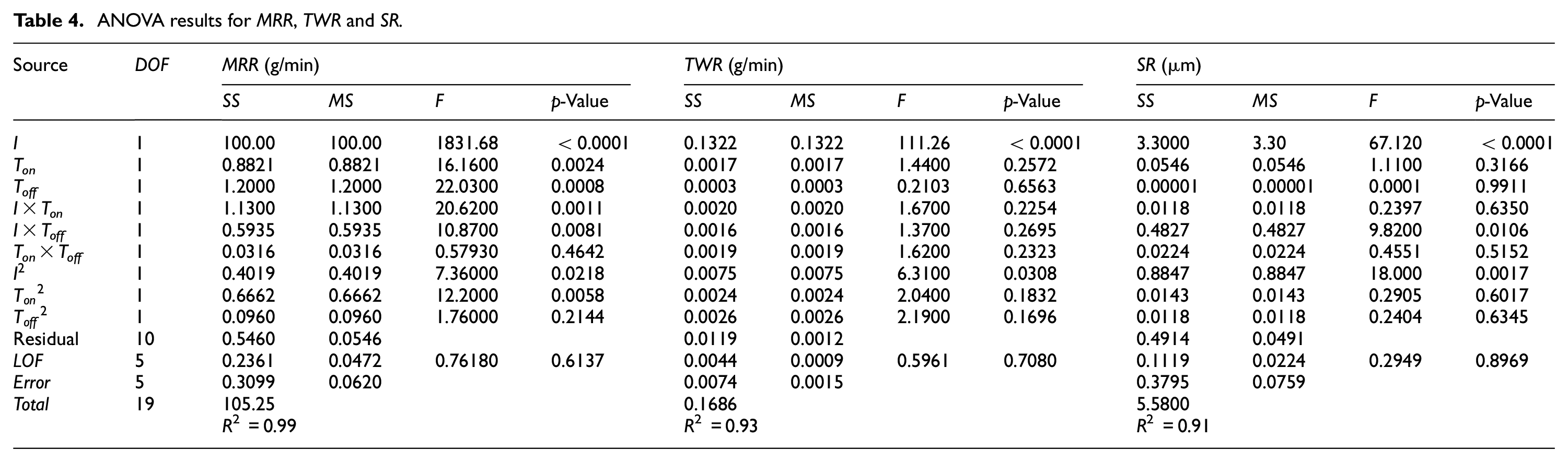
Experimental results for the new electrodes’ machining performances were obtained using FCCCD which are shown in Table 3. Table 4 presented the results for ANOVA of MRR, TWR and SR. Here, SS, V and DOF signify sum of square, variance and degree of freedom respectively; R2 and LOF represent coefficient of variance and lack of fit respectively. R2 shows the percentage of total variation that the model can explain. It is evident from Table 4 that for all three machining performances, the value of R2 is greater than 0.90, which is high, and it implies that the models can explain more than 90% variations in the machining performance. ANOVA results shows that the quadratic model can effectively predict the machining performances. It is observed from Table 4 that all three main EDM parameters that is, I, Ton, Toff are significant for MRR as p-value
Experimental results for machining performances.
ANOVA results for MRR, TWR and SR.
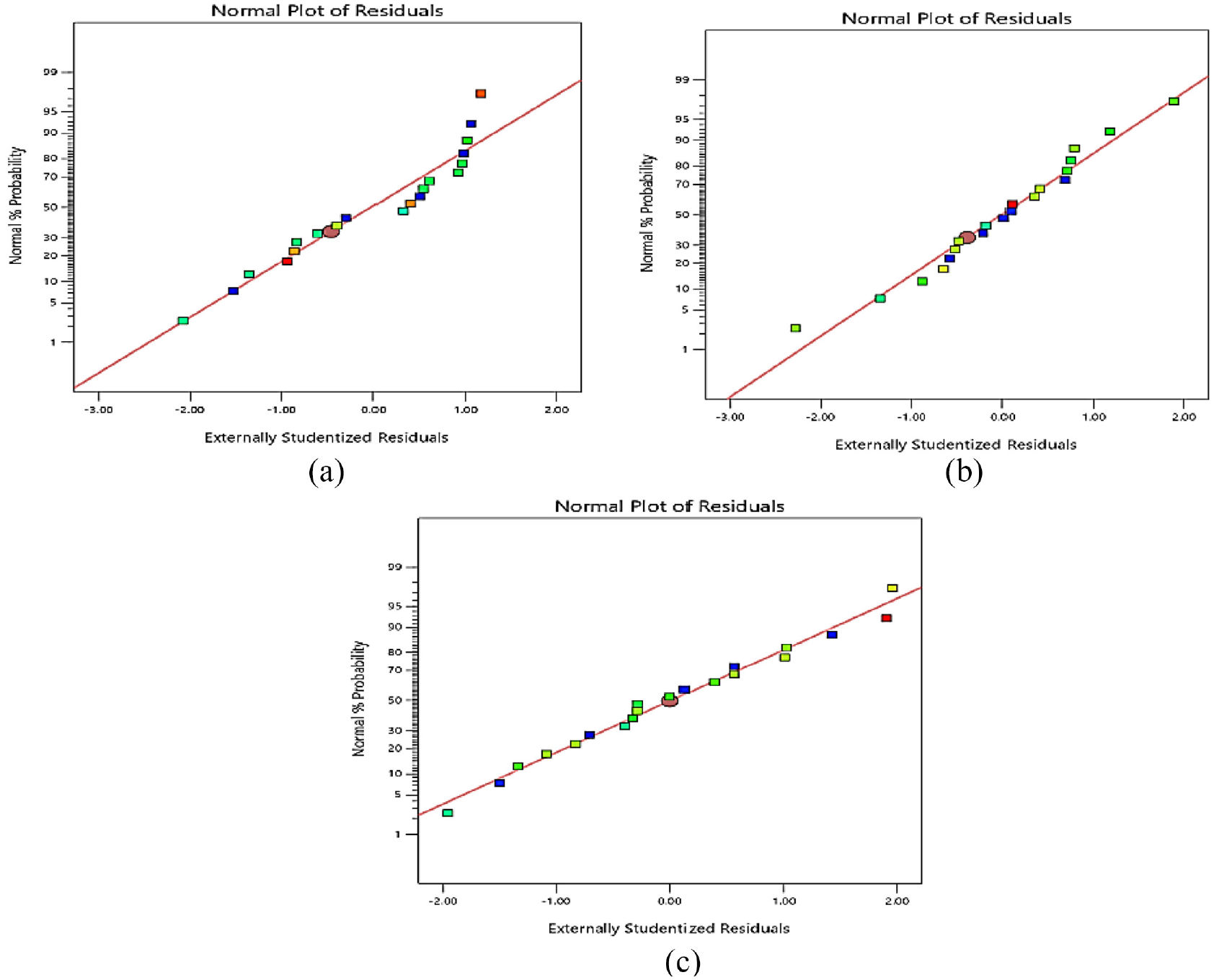
Normality plot for: (a) MRR, (b) TWR and (c) SR.
The effect of EDM parameters on the machining performances was analysed using response graphs and 3D response surface plots. Table 4 shows that for MRR, all three parameters (I, Ton and Toff) and two interactions (I × Ton and I × Toff) are significant, but for TWR, I and I2 are significant, and for SR, I, I2 and interaction I × Toff are significant. For the sake of uniformity, response surface plots for I × Ton and I × Toff are explained for all three performance measures.
Material removal rate (MRR)
Figure 3 shows the response graph for MRR whereas Figures 4 and 5 exhibit the 3D surface plots for MRR.
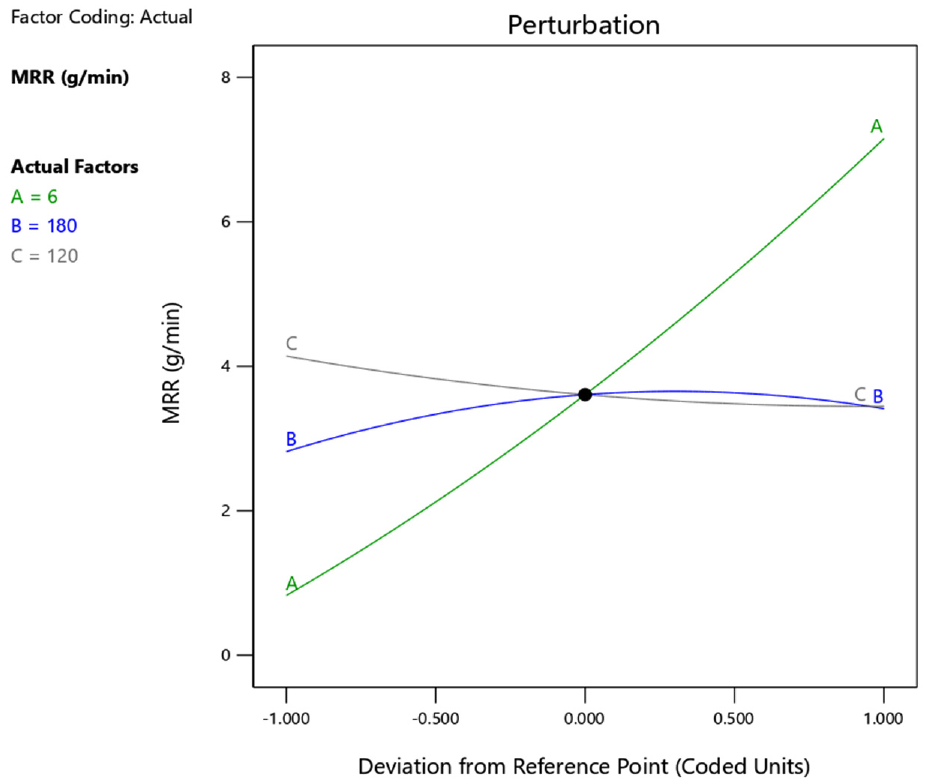
Response graph for MRR.
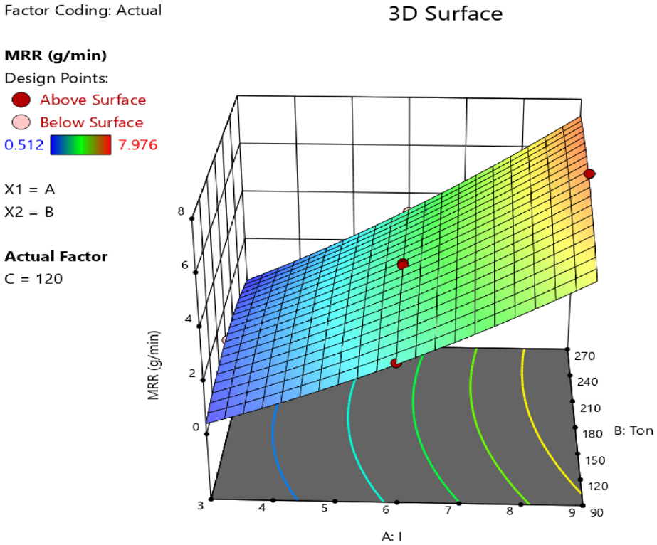
3D response surface plot for MRR (I × Ton).
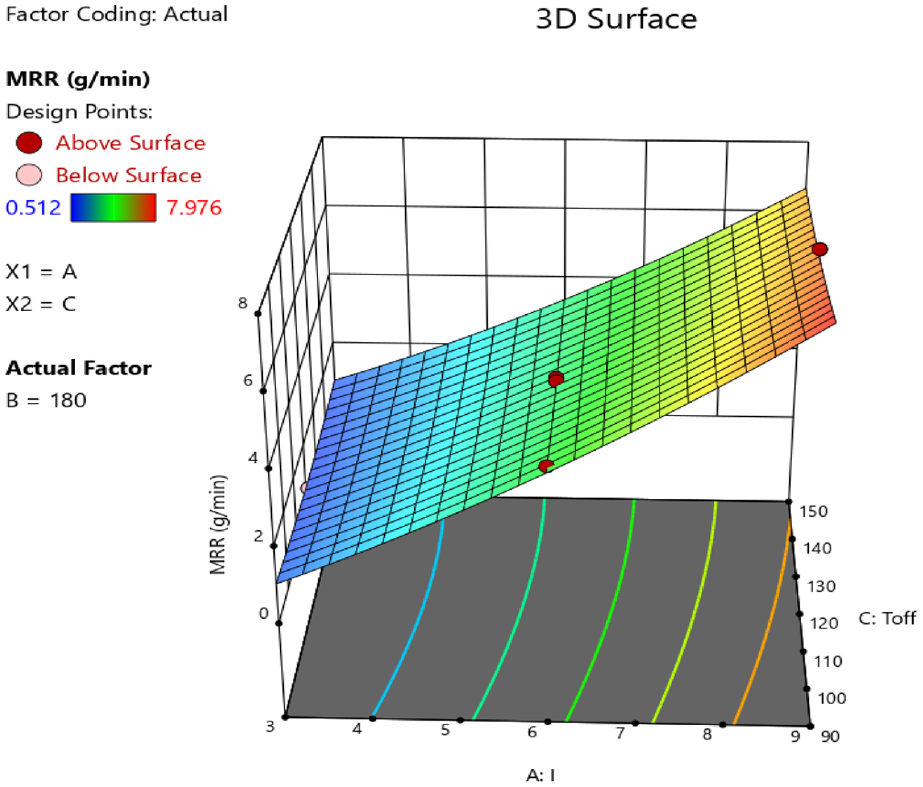
3D response surface plot for MRR (I × Toff).
It can be seen from Figure 3 that MRR increases with an increase in I. With the rise in Ton, MRR first increases, but after sometime it begins to decrease. However, MRR continuously decreases with an increase in Toff. The 3D response surface plots presented in Figure 4 (I × Ton) and Figure 5 (I × Toff) also lead to the same inferences. Intensity of spark energy increases with the rise in the value of current (I) which helps in easy melting and removal of the material leading to increased MRR.8,30 This increase in MRR continues with further increase in I. Increase in Ton also increases the spark energy initially, resulting in higher MRR (Figure 4). However, with the continuous machining, the black carbon layer gets deposited on the bottom face of the electrode, which reduces the spark’s intensity and hence spark energy decreases gradually,8,31 leading to a decrease in the MRR but still the value of MRR is more than the value obtained at lower I. Increase in Toff decreases the MRR (Figure 5). As the Toff decreases, the time between succeeding sparks is increased and enough time is available for solidification of partially melted material. 8 This solidified material is melted and removed in the next EDM cycle thereby decreasing the MRR in the subsequent EDM cycles. An increase in Toff also provides ample time for re-establishment of dielectric strength, and to overcome it substantial energy is used due to which MRR decreases.8,32
Tool wear rate (TWR)
Figure 6 displays the response graph for TWR. 3D surface plots for TWR are presented in Figure 7 (I × Ton) and Figure 8 (I × Toff). Figure 6 shows an increase in TWR with an increase in I. TWR initially increases with an increase in Ton, but with further increase in Ton, TWR starts decreasing. TWR initially decreases with an increase in Toff, but when Toff is further increased then TWR also increases.
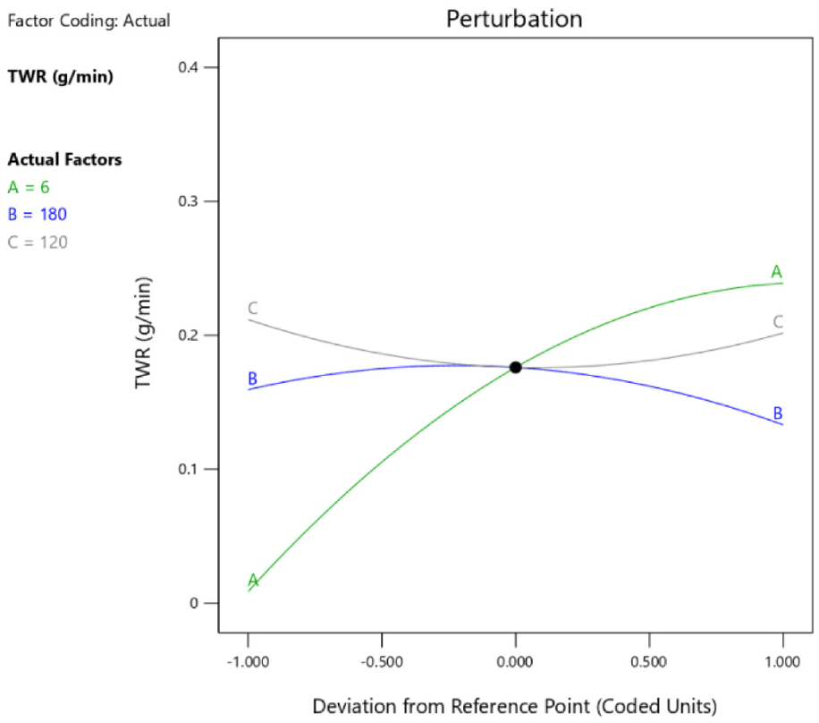
Response graph for TWR.
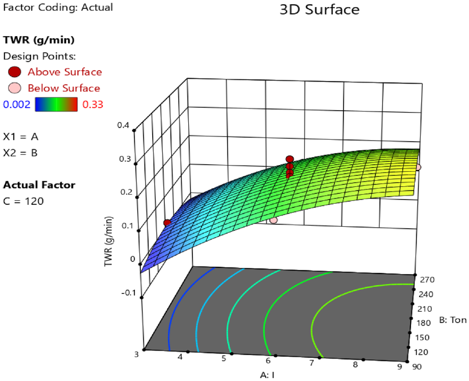
3D response surface plot for TWR (I × Ton).
3D response surface plots as shown in Figures 7 and 8, also depict that TWR increases when current increases. This may be because as current increases, intensity of the spark energy increases which causes removal of more material from the electrode bottom surface. 8 At higher Ton the electrode produces more intense spark, and hence it wears out fast. With progress in machining and increased Ton, the diameter of plasma (formed due to flow of ions between electrode and tool) spreads, and convective heat transmitted to the electrode is reduced. However, heat transmitted to the workpiece is increased, which reduces TWR and increases MRR. 33 As machining progresses, black carbon layer gets deposited on the bottom surface of the electrode which decreases the TWR.8,29,34
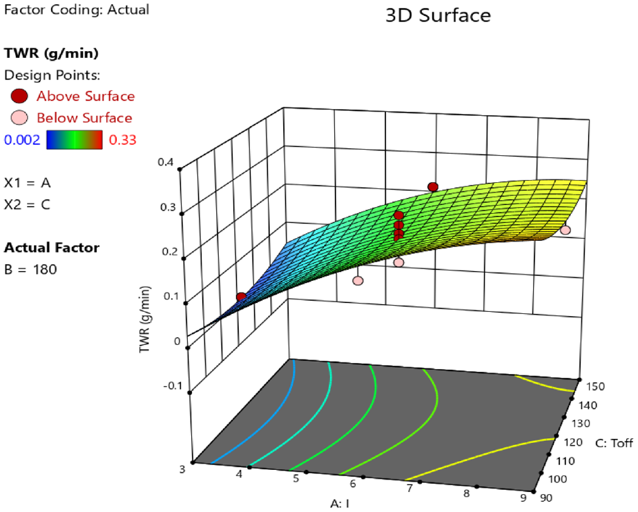
3D response surface plot for TWR (I × Toff).
TWR decreases with an increase in Toff. This happens because of reduction in the frequency of sparking and also availability of adequate time for re-establishing the strength of dielectric.8,32 When Toff is at peak, then the circulation of the dielectric is more which facilitates easy removal of the material from the workpiece cavity and worn out electrode. As wear of electrode is very little, the removal of worn-out particles from electrode marginally increases TWR (Figure 8).
Surface roughness (SR)
Figure 9 shows the response graph, whereas Figures 10 and 11 display the 3D surface plots for SR. Response graph and 3D response surface plots reveal that SR increases with an increase in I and Ton. The reason for this may be that at lower values of I and Ton, the size of the crater formed by every spark is small and it may lead to low value of SR. At higher values of I and Ton, more material is removed due to which crater size increases and it is likely that the surface of the machined cavity becomes uneven that may lead to an increase in the SR value. 35 Figure 9 clearly shows that the effect of I on surface roughness is more as compared to the effect of both Ton and Toff which implies that I is the most dominating parameter for affecting SR, and this can also be confirmed from the ANOVA results presented in Table 4. With the increase in Toff marginal decrease in SR is observed as dielectric circulation can easily remove the irregular machined particle (debris) formed during machining. Due to removal of the debris the unevenness of the machined surface reduces which may reduce the value of SR.
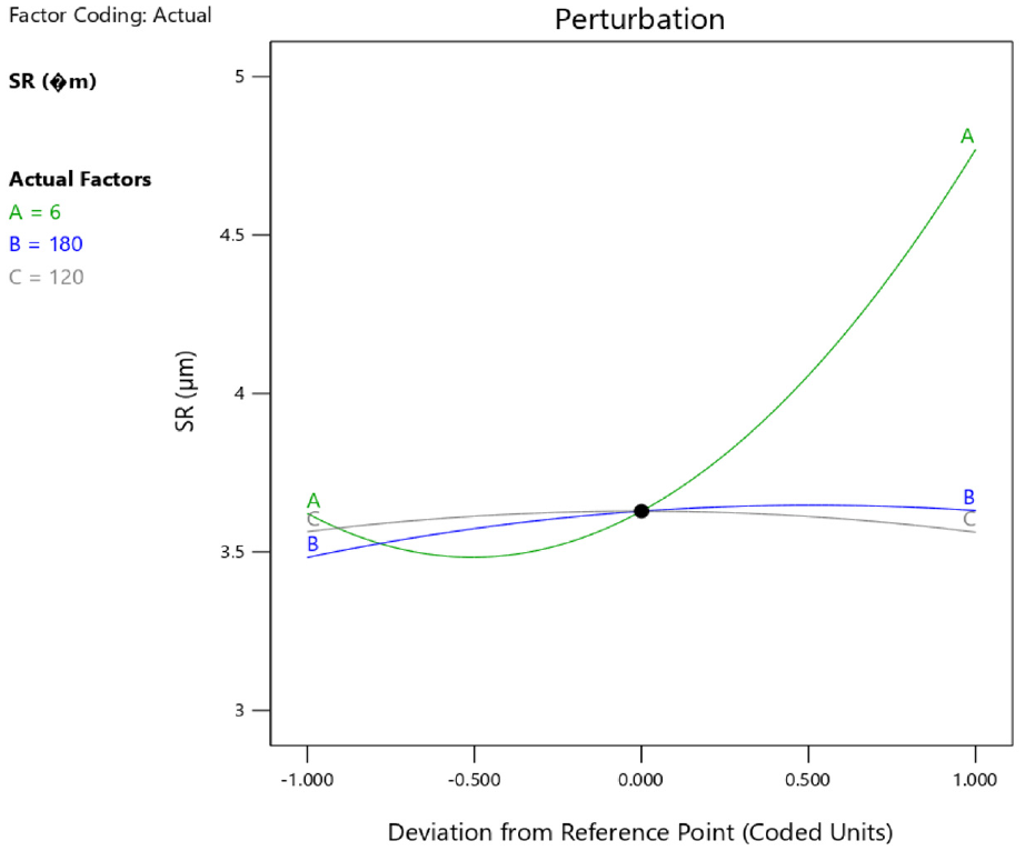
Response graph for SR.
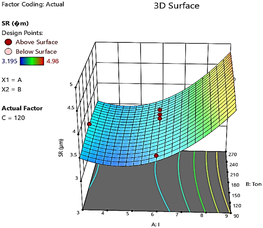
3D response surface plot for SR (I × Ton).
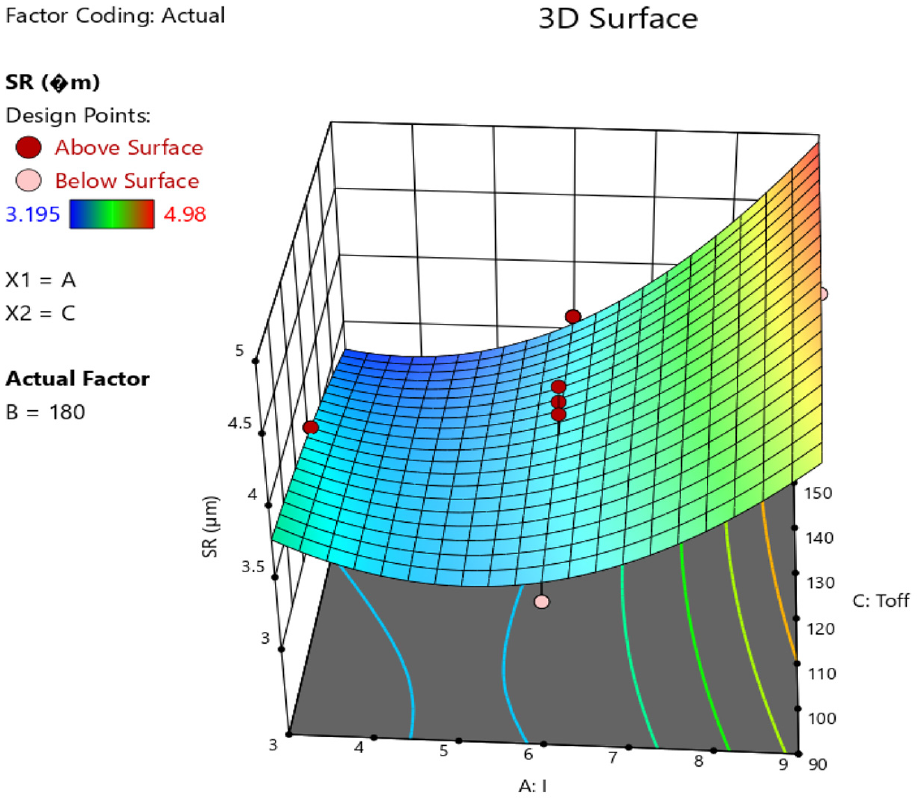
3D response surface plot for SR (I × Toff).
From the result presented above, it is inferred that the current (I) is the dominating parameter for affecting MRR, TWR and SR when EDM is done using the new electrode.
Multi-performance optimization
Three conflicting machining performances, that is, MRR, TWR and SR, were involved in the present study and they were optimized simultaneously using the TLBO algorithm. The objective was to simultaneously maximize MRR and minimize both TWR and SR. Therefore, the objective function was formulated as given in equation (11) and it was subjected to constraints given in equation (12).
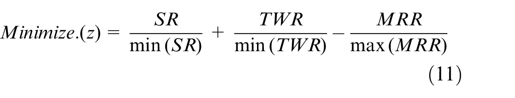
Subject to:
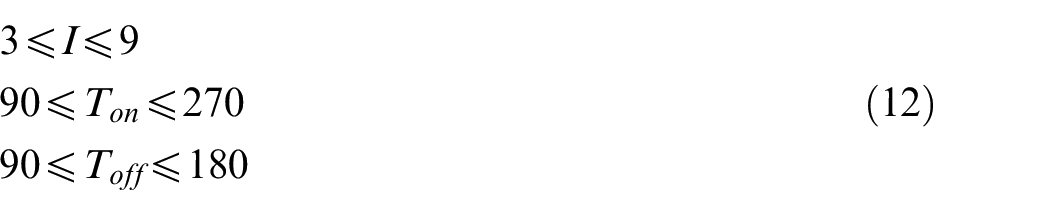
The above optimization problem was solved using TLBO algorithm considering a population size of 50. Further, a complete interaction in the learner phase was also assumed. Figure 12 shows the value of the objective function (z) with an increasing number of iterations. It can be clearly seen from Figure 12 that the solution converges quickly only after a few iterations. Further, the minimum value of the objective function (z) was found as −6.968, and it was obtained at the EDM parameter setting of I = 9 A, Ton = 111.819 µs, Toff = 90 µs. The values of the machining performances at the optimal parameter setting were MRR = 7.2098 g/min, TWR = 0.3036 g/min and SR = 4.2805 µm.
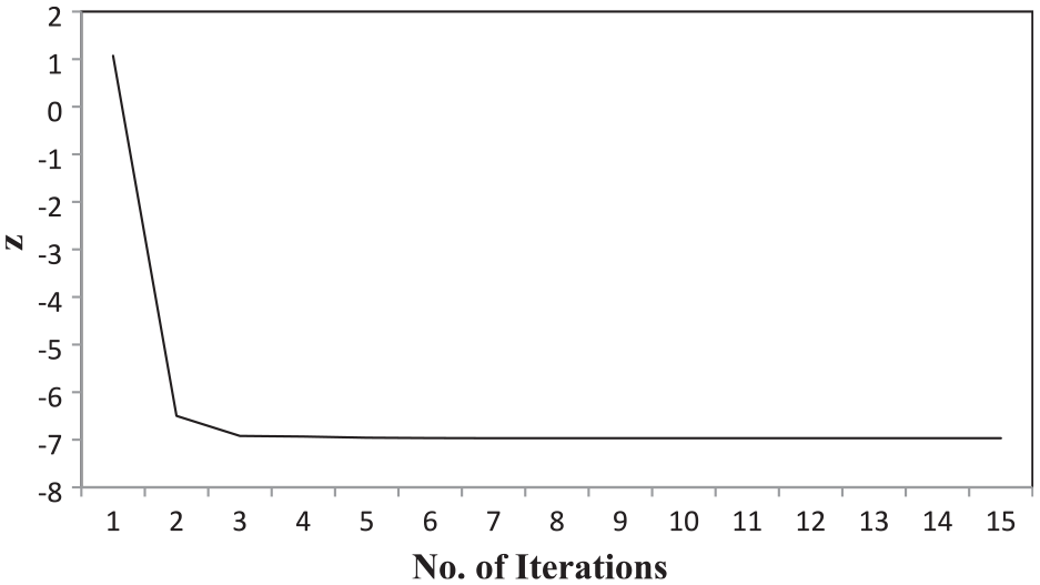
Objective function values versus number of iterations.
Comparison of machining performances
Effectiveness of the new electrode has been established through a comparison between its performance and the performance of the SC electrode and FDM-EMR electrode under the same machining parameters setting as reported in the literature. 8
Comparison of MRR, TWR and SR are presented in Figures 13 to 15, respectively. It can be observed from Figure 13 that the new electrode provides higher MRR as compared to the FDM-EMR electrode but, lower MRR when compared with SC electrode. Figure 14 reveals that TWR of the new electrode is higher than that of other electrodes. However, TWR of the new electrode at lower values of the machining parameters is less than that of FDM-EMR electrode, as indicated by point A in Figure 14. Hence, it can be suggested that the new electrode is suitable for finish machining conditions when lower TWR is desired. Figure 15 depicts that SR produced by the new electrode is quite high when compared with other electrodes. The uneven deposition of copper at the periphery of the bottom face of the ABS P400 based electrode causes the continuous variation in the current density at the corner which leads to higher SR. Overall, it can be concluded that for MRR and TWR of the new electrode is comparable with other electrodes but with regard to SR, the metallization needs further improvement in order to enhance its performance.
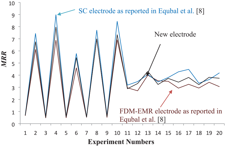
Comparison of MRR for different electrodes.
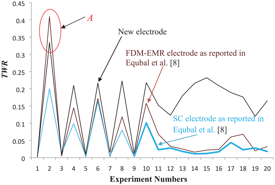
Comparison of TWR for different electrodes.
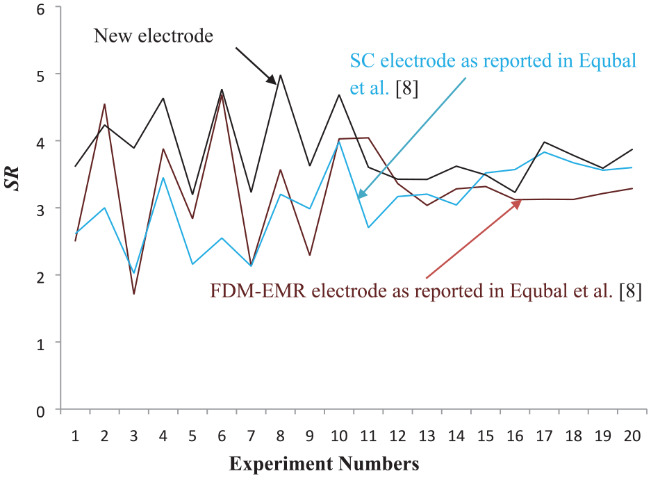
Comparison of SR for different electrodes.
Conclusions
This paper experimentally evaluated the machining performance of a new ABS P400 based EDM electrode which was produced using FDM process and a novel metallization route of Al-C paste followed by electroplating of copper on it. Three EDM parameters (I, Ton and Toff), each at three levels, were used for producing cavity in mild steel workpiece using the electrodes. Machining performances were measured in terms of MRR, TWR and SR. ANOVA, response graphs and 3D surface plots were used to evaluate the experimental results. Further, multi-performance optimization was carried out using a TLBO algorithm. In addition, the efficacy of the new EDM electrode was established through a comparison between its performance and the performance of the SC electrode and FDM-EMR electrode under the same machining parameters setting. 8 Important conclusions drawn from the study are listed as under:
Mild steel can be successfully machined by ABS electrode produced by FDM followed by a novel metallization method comprising of providing a coating of Al-C paste on it and then its copper electroplating to make it suitable for EDM application.
Out of three EDM parameters that is, I, Ton and Toff, I was the most dominating one for affecting MRR, TWR and SR.
Quadratic models developed using RSM were quite effective and accurate in predicting the values of performance measures for the EDM parameters’ values.
Teaching learning based optimization algorithm produced an optimal setting of the EDM parameters for optimum multi performances with a small number of iterations.
For the same machining parameters setting, all machining performances, except SR, of the new electrode and the previously developed electrodes were comparable. However, the new electrode produced more SR, which might be reduced using improved metallization methods.
Footnotes
Declaration of conflicting interests
The author(s) declared no potential conflicts of interest with respect to the research, authorship, and/or publication of this article.
Funding
The author(s) disclosed receipt of the following financial support for the research, authorship, and/or publication of this article: The authors extend their appreciation to the Deanship of Scientific Research at King Khalid University for funding this work through the Large Groups Project under grant number (RGP.2 /101/43).