
Abstract
Thermal drilling is a novel chipless sheet metal drilling process that uses a rotating thermal drill tool to pierce and form a bushing shape hole. In this work, thermal drilling process is successfully employed to drill the DP 600 grade–type galvanized steel with a thickness of 2 mm. The influence of different spindle rotational speeds such as 1600, 2000 and 2400 r/min on the formation of bushing height, surface roughness, microhardness and microstructure of the thermal-drilled holes are investigated in detail. Process parameters such as feed rate, thermal drill angle and workpiece thickness were held constant in order to explore the influence of rotational speed on the quality characteristics of the thermal drilling process. It has been found that the bushing height was improved with increasing of rotational speed, but the petal formation at the outer edge of the bush is decreased. Surface roughness tests indicate that the better surface quality drilled hole could be obtained at the highest rotational speed of 2400 r/min. The microstructural investigation confirmed that a new result of Lüders band marks was formed inside the thermal-drilled holes because high thermal stress and yielding of galvanized steel material.
Introduction
In conventional drilling process, large amount of chips were generated from the workpiece, which get adhered with the tool as well as the workpiece and then damage the surface quality of a finished hole.1–4 The reliability of joint strength depends on the characteristics such as efficient screw thread strength and clamping heavy loads which are not obtained through this way of conventional procedure. Besides, fastening of sheet metals or thin-walled structures via conventional drilling method requires threaded inserts or welded nuts. But those approaches have some limitations such as thermal distortion, and twisting problem occurs during joining circumstances.
Above problems that arise from conventional drilling are completely abolished by the practice of thermal drilling process.5–7 They can be eliminated by the formation of bushing below the drilled hole which has a height three to four times higher than the workpiece thickness, which increase the thread-producing portion inside the hole which is used to enhance the fastening strength for the duration of handling a heavy load.8–10
The thermal drilling process is an unconventional hole-producing method which has greater trendy potential for the drilling of sheet metals.11–13 It has the main advantage of green manufacturing process without environmental degradation. It is also named as thermal friction drilling, friction stir drilling, thermo-mechanical drilling and form drilling.14,15 The graphical presentation of thermal drilling process is shown in Figure 1. This process is completed by the following five stages. In the first stage, the center section approaches and starts to pierce the workpiece. This tends to create an indentation in the drilling zone. In the second stage, the conical section of the tool starts to penetrate into the workpiece. At that time, frictional heat is produced at the contact between the tool and workpiece. Due to which, the workpiece material gets softened at the drilling zone. Next, in the third stage, the conical section of the tool is completely pierced into the workpiece, which leads to form a conical cavity, and subsequently, the cylindrical section starts to pierce into the workpiece. Then the molten workpiece material comes out from the drilling zone and moves in the upward and downward direction. Simultaneously, this tool has been continuously moved to push the material aside in order to form a bush by the piercing action of the cylindrical section of the tool. Then in the four-stage, the cylindrical section is completely penetrated into the workpiece which leads to form a bushing shape drilled hole, and following that the shoulder section compresses the unwanted burr on the top surface of the hole to form a circular washer or boss. In the fifth step, the tool retracts to its initial home position and then unloads the finished workpiece material from the workpiece-holding device.
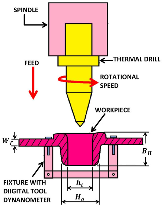
Schematic arrangement of thermal drilling experiment setup.
The selection of material and design for manufacturing of thermal drill tool are very essential to avoid the unnecessary situations of wearing as well as cracking of tool during the production of more number of holes. The surface quality of holes and formation of bushing height are used to specify the efficiency of the thermal drilling process. Galvanized steel is a dual-phase steel which has the dual-phase structure such as ferritic and martensitic stainless steel, and it is selected as the workpiece material for this work due to its crucial benefits in the automobile fields. In order to prevent the corrosion effect, various grades of higher strength characteristics of galvanized steels are extensively used in the car body manufacturing industry. Also, it is a highly dominated material and widely used for designing new advanced lightweight automobile. It offers greater strength and work hardening activities as well as ductile property when compared with traditional steel and is also well suitable for fabrication of strength-related structural components in automobiles. 16
Some of the literature works related to the thermal drilling process are discussed below: Miller et al. 17 experimentally carried out thermal drilling on different materials such as Al380 steel, Mg alloy and AISI 1020 steel by using coated TiC and tungsten carbide (WC) thermal drills. Also, Miller et al. 18 extend their research work to investigate tool wear during thermal drilling process on AISI 1015 steel material. Lee et al. 19 studied the effect of processing conditions such as rotational speed, feed rate and diameter of drill on roundness, surface roughness and hardness in the thermal drilling of IN-713C alloy material. Chow et al. 20 determined the optimum process parameter for thermal drilling using Taguchi method. In their study, Taguchi L18 orthogonal arrays were utilized to conduct the experiments, and they varied the process parameters such as drilling speed, feed rate, friction angle and frictional contact area ratio. Lee et al. 21 compared the performance of coated and uncoated WC thermal drilling tools on AISI 304 steel. It was also examined for parameters such as surface roughness, axial force, wear of tool and tool temperature. Ku et al. 22 worked on the drilling of AISI 304 steel material in thermal drilling process. The influence of drilling parameters on microstructure and bushing height were studied.
Few researchers had investigated the influence of feed rate, drill angle and workpiece thickness on the bushing height. But, to the best of the authors’ knowledge, the effect of rotational speed of thermal drill on bushing height and microstructural aspects of the bushing was not given due consideration. This work is more significant to the researchers and practitioners, since enhancement of bushing height is essential for better fastening of sheet metals.
Materials and methods
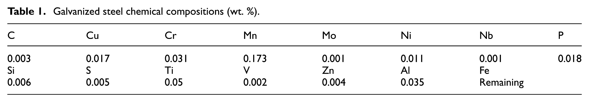
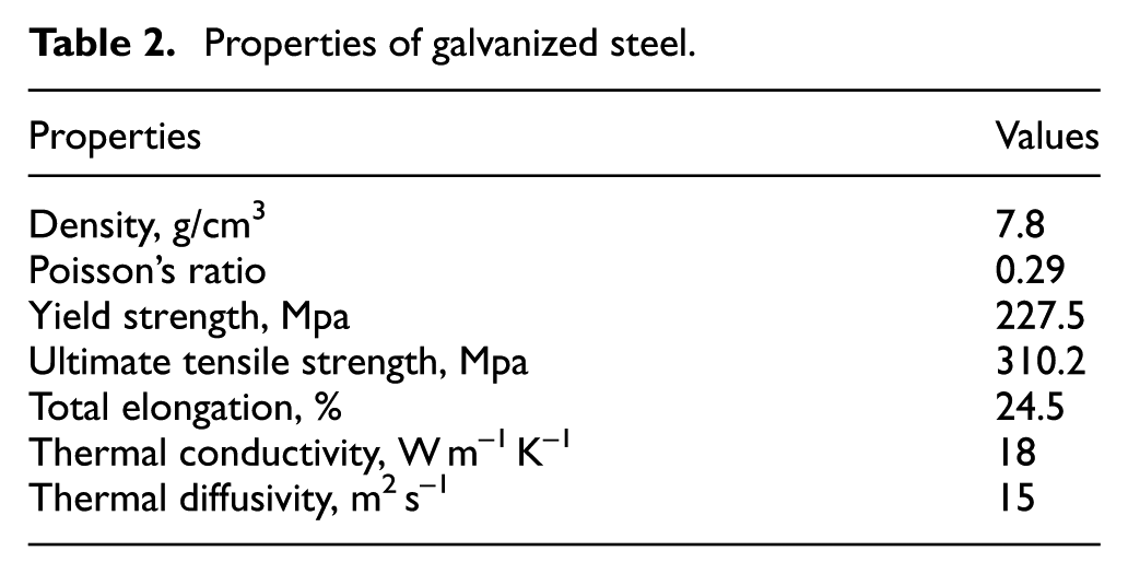
Base material galvanized steel sheets with 2-mm thickness were machined to get the dimension of size 130 × 50 mm using a power hacksaw machine. This material is a zinc-coated designation of DP 600 grade–type galvanized steel. Figure 2 shows the sample of galvanized steel which was prepared for the thermal drilling process. The chemical composition and properties of galvanized steel are given in Tables 1 and 2, respectively. The WC material is selected as a tool material due to its high strength and capability to drill the steel sheet. Figure 3 shows the schematic representation and fabricated thermal drilling tool. It has the following dimensions: 6 mm diameter (d), 20 mm shank section length (Dsh), 8 mm shoulder section (Dso), 15 mm cylinder section length (Dcy), 5 mm conical section length (Dco) and 2.5 mm center section length (Dce). The angle of conical section is 45°
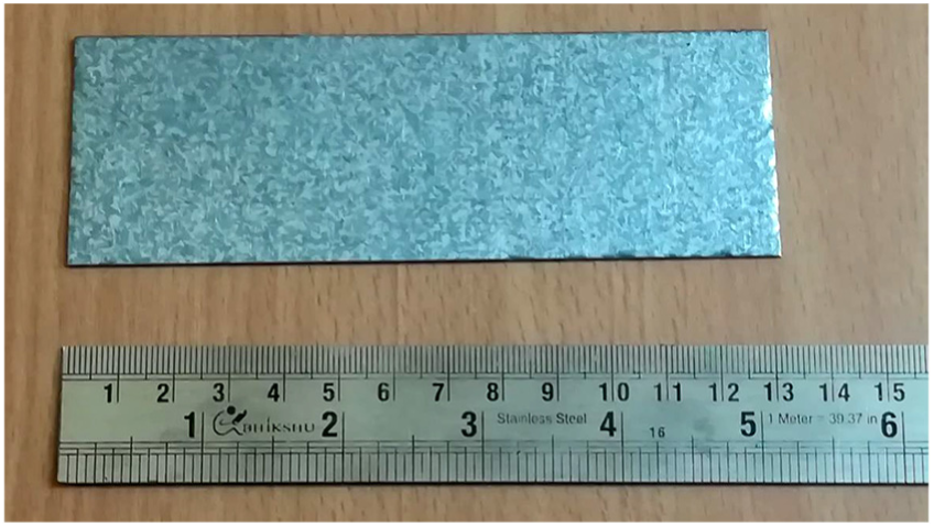
Sample prepared for thermal drilling process.
Galvanized steel chemical compositions (wt. %).
Properties of galvanized steel.
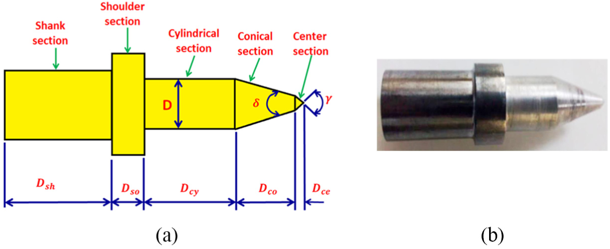
(a) Dimensions of thermal drill tool and (b) fabricated tool.
Stylus type SJ-210 Mitutoyo instrument is used to measure the surface roughness inside the bushing of thermal-drilled galvanized steel holes. Before that, the specimen is positioned in the fixture. The stylus is allowed to move on a straight line of sampling length 2 mm along the axis of the hole. Ra (center line average) is the surface roughness parameter, and it is considered in this work. Ra is the average of peak heights and valleys calculated arithmetically, measured with the sampling length of 2 mm. The surface roughness is expressed in equation (1)
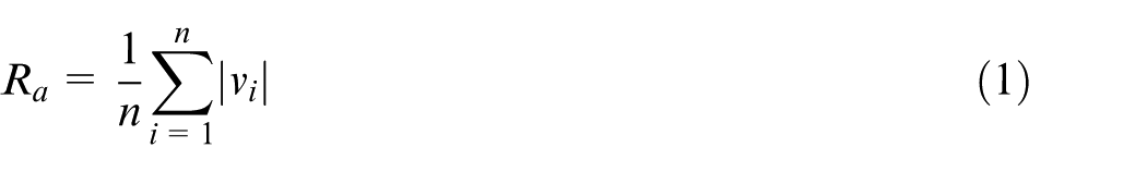
where
Digital drilling tool dynamometer was attached with the workpiece-holding device in order to measure the axial forces occurred during the process. Bushing height of the samples was measured by CD-12C Mitutoyo Digital Vernier Caliper. According to this process, the amount of material that gets displaced is equal to the amount of deformed material in order to form a bush below the drilled hole. Therefore, the height of bushing formed by thermal drilling process is to be calculated by the equation (2)
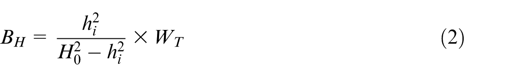
where
Before the microstructural investigation, the samples are backed with the bakelite material and etched with a Nital reagent for the duration of 15 s in order to get the required quality microstructure image of the sample. Microstructural examinations were conducted by using Carl Zeiss EVO 18 Scanning Electron Microscope.
Microhardness was determined using Wolpert Wilson Micro Vickers hardness tester (model MVD-402) on the wall of the bushing. Hardness test was conducted with operating conditions such as a dead load of 500 g and a holding time of 30 s. Indents were made on the drilled specimen. The indenter is removed, and the indentation is measured using an optical microscope. Using the following equation (3), microhardness is determined
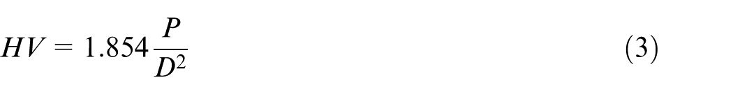
where HV denotes Vickers hardness; P is the load in kgf and D is the arithmetic mean of the two diagonals in mm.
Results and discussion
The surface roughness, bushing height, microhardness and microstructure of all samples of thermal-drilled holes in the galvanized steel were examined successfully.
Effect of rotational speed on the surface roughness
The effect of rotational speed on the surface roughness of the thermal-drilled galvanized steel hole is shown in Figure 4. The surface roughness of thermal-drilled hole produced at 1600 r/min rotational speed varied from 2.034 to 3.201 μm. At 2000 and 2400 r/min rotational speed, the surface roughness varied from 1.918 to 2.584 μm and from 1.451 to 1.898 μm, respectively. The maximum percentage of variation in the surface roughness of the thermal-drilled hole, while increasing of rotational speed from 1600 to 2400 r/min was 52.33%. When the rotational speed of spindle was increased from 1600 to 2400 r/min, thermal energy increased due to increase in frictional heat rapidly at the interface of thermal drill and workpiece. This was used to increase the capability of thermal drilling process through softening of material at the drilling zone. Figure 4 showed the images of the thermal-drilled holes produced in the galvanized steel material under the conditions of three different rotational speeds such as 1600, 2000 and 2400 r/min. It was found that the thermal-drilled hole produced at 2400 r/min had the greatest finished hole with superior surface integrity. On the other hand, some amount of molten galvanized steel material tends to adhere with the thermal drill at the lower rotational speed of 1600 r/min. Therefore, during withdrawal of thermal drill after the drilling process, the adhered material creates scratch marks inside the hole, which affects the surface quality of the drilled hole.
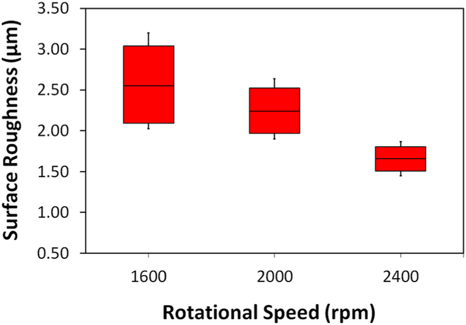
Surface roughness of thermal-drilled hole versus rotational speed.
Effect of rotational speed on the bushing height
The effect of rotational speed on bushing height and petal formation at the lower edge, that is, hemlines of the bushing formed in samples, was investigated. The bushings heights as shown in Figure 5 were formed by the action of three different rotational speeds such as 1600, 2000 and 2400 r/min. Different views, that is, top portion view, bottom portion view and cross-sectioned bushing of thermal-drilled holes were produced at the rotational speed of 1600 r/min from Figure 5(a)–(c), at the rotational speed of 2000 r/min from Figure 5(d)–(f) and at the rotational speed of 2400 r/min from Figure 5(g)–(i). Digital vernier caliper instrument was used to determine the bushing heights which were measured at three different locations in the bushing of galvanized steel and then averaged the three different bushing height values. Figure 6 shows the measured bushing height and axial force during the thermal drilling of galvanized steel. The measured bushing height at the rotational speed of 1600 2000 and 2400 r/min were 4.282, 5.457 and 5.821 mm, respectively. The alternation in the bushing height of thermal-drilled workpiece while increasing the rotational speed from 1600 to 2400 r/min is 26.43%. Also, at greater rotational speed, the bushing height increases with fewer petals formation at the lower edge of the bushing. Since the flowability of softened material was increased at higher rotational speed due to the higher heat generation. The rate of heat generation during thermal drilling process is mainly dependent on rotational speed. As the temperature increases, flowability increases and the material starts flowing along the axial force of the thermal drill. The rate of formation of a bushing is uniform with a less tendency to crack on the lower side. This eventually results in the formation of fewer petals. The formation of petals is higher at 1600 r/min, due to the following two reasons: the low temperature generation exists in between the tool and workpiece which affects the formation of the bushing and also decreases the bushing height, and at a lower rotational speed of 1600 r/min, the tool approaches the bottom surface of galvanized steel, at that time more amount of axial force is created. This axial force initiate ruptures at the lower edges of the bushing and at the end rupture becomes petals formation.
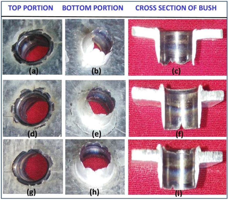
Different views of thermal-drilled holes produced ((a)–(c)) at 1600 r/min, ((d)–(f)) at 2000 r/min and ((g)–(i)) at 2400 r/min.
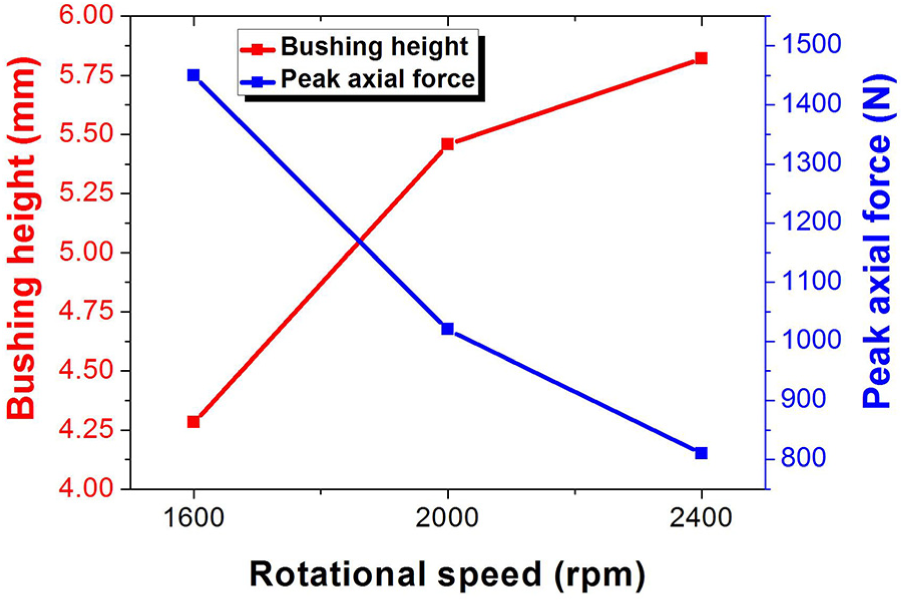
Rotational speeds versus bushing height and peak axial force.
Also in Figure 6, the peak axial forces were varied with the alternation of rotational speed from 1600 to 2400 r/min. It was found that the axial force was decreased with the increase of rotational speed. Because, the frictional heat is increased while at higher rotational speed, due to which the drilling tool is easily penetrated into it. Hence, the axial force required for drilling the material was reduced. The measured peak axial force values at the different rotational speeds such as 1600, 2000 and 2400 r/min are 1450, 1020 and 810 N, respectively.
Effect of rotational speed on the microhardness
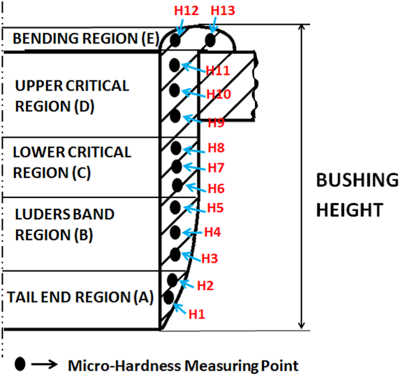
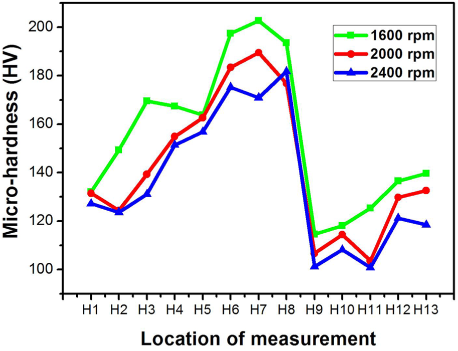
The location of the microhardness measurement is shown in Figure 7. The microhardness test was conducted at the bushing wall of thermal-drilled holes which are processed at the three different rotational speeds such as 1600, 2000 and 2400 r/min. Figure 8 shows the microhardness variations at the three rotational speeds of the thermal drill. The values of microhardness are given in Table 3. When thermal drilling at 1600 r/min rotational speed, a less amount of heat energy is generated, due to that a small surface area was heated. Therefore, the softened material cools very fast, creating fine grains around the hole wall. Thus, the greater hardness (198.5 HV) was obtained in the thermal drilling at the lower rotational speed of 1600 r/min. The greater heat energy is generated by thermal drilling at 2000 and 2400 r/min when compared to the low rotational speed of 1600 r/min. This phenomenon results in more soften material under high temperature and a larger surface area being heated. Due to that, the cooling of workpiece gets longer leading to the formation of larger grains structure along the hole wall and reduction in microhardness of hole wall. The microhardness of 183.4 and 181.8 HV were obtained at the 2000 and 2400 r/min rotational speed, respectively.
Schematic diagram of microhardness test.
Measurement of microhardness on the wall of holes
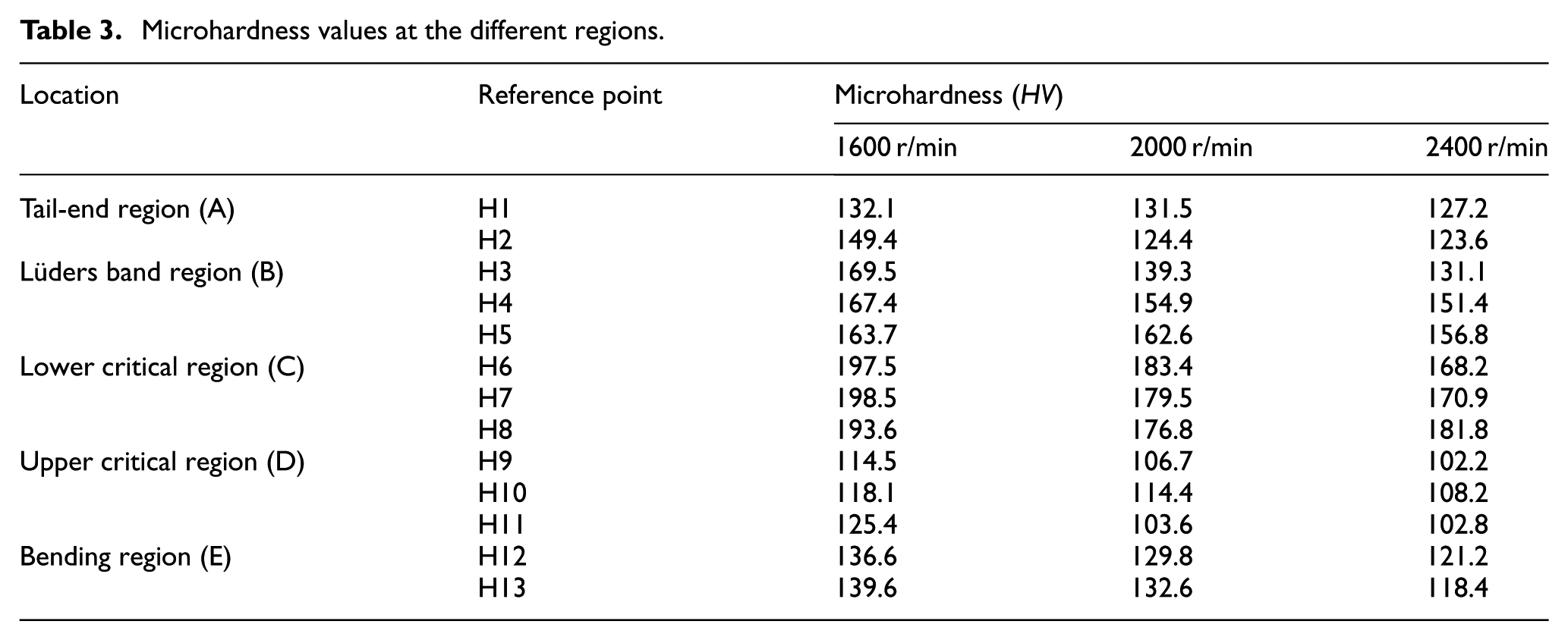
Microhardness values at the different regions.
Effect of rotational speed on the microstructure
Figure 9 shows the microstructure structure of dual-phase galvanized steel. This microstructure shows the distribution of coarse ferrite and fine martensite grain structure. Also, it offers an excellent combination of strength and drawability as a result of their microstructure, in which a hard martensitic phase is dispersed in a soft ferritic matrix. Due to high strain hardenability, it possesses good strain redistribution capacity. Figure 10 shows the schematic representation of different regions in the thermal-drilled galvanized steel. This shows the material flow of a thermally drilled hole, which resembles the surface characteristics feature of a hot extruded component.
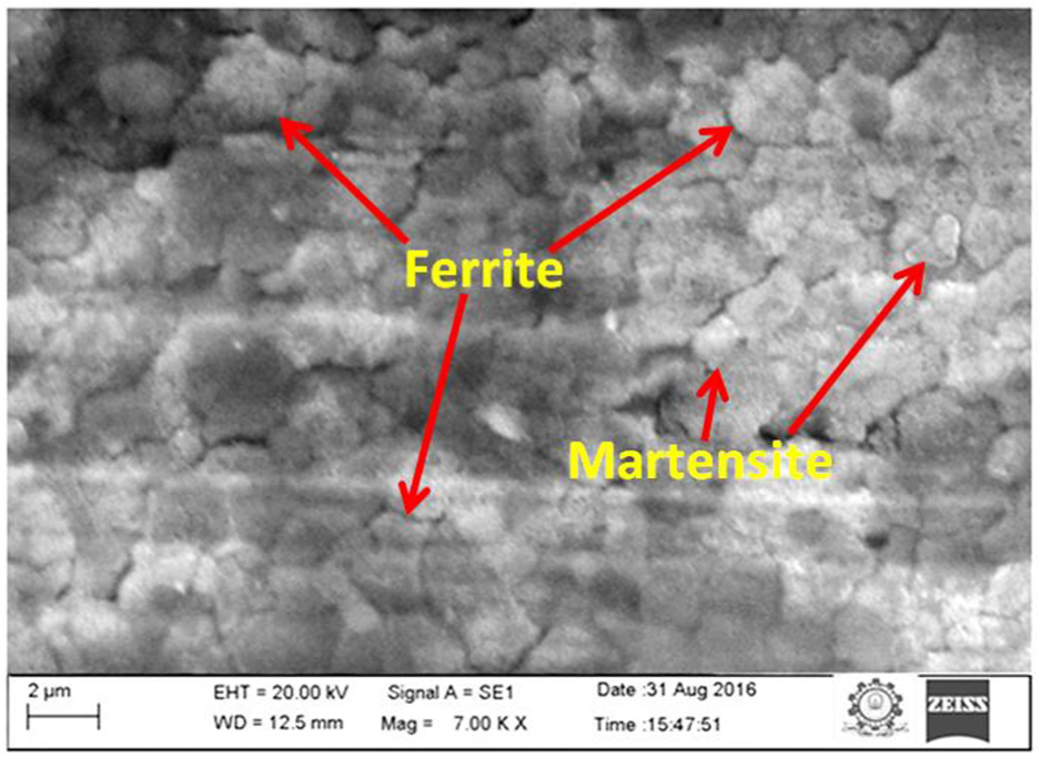
Initial microstructure of the galvanized steel.
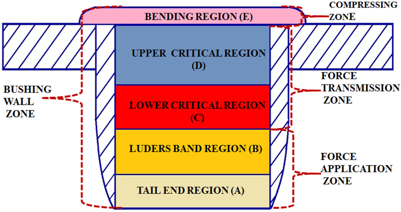
Pictorial representation of different regions in thermal-drilled hole.
The thermal properties of galvanized steel and the rotational speed of thermal drill govern the extrusion level of material and heat generation rate. As a result, the inner surface of the drilled hole has divided into different hot working regions according to the mechanism of bushing formation. It is shown in Figure 10, in which, A represents the tail-end region, B represents the Lüders band region, C represents the lower critical region, D represents the upper critical region and E represents the bending region.
Effect of rotational speed on the tail-end region
Initially, the center section of thermal drill starts to pierce when the temperature of galvanized steel increases due to adiabatic heat generation at the interface of rotating thermal drill tool and workpiece. Because of the continuous forward movement of the tool, the center section of tool pierces completely and then conical section of tool begins to pierce the galvanized steel. Here, the material present in front of rotating thermal drill is forced to form a conical cavity. A preliminary deformation happens while the galvanized steel is heated above the critical temperature and also internal stresses go beyond the flow stress of the workpiece material; hence, the flowability of the material is increased. At that moment, the softened workpiece material is forced by the action of the thermo-mechanical phenomenon to transfer in both upward and downward direction. Thus, this initially formed region was named as tail-end region (A).
The microstructures at the tail-end region (A) produced for the different rotational speeds such as 1600, 2000 and 2400 r/min are shown in Figure 11. The microstructure at the lower rotational speed of 1600 r/min in Figure 11(a) shows more amount of small pits that are displayed on the surface of the drilled hole. This damage is initiated by the influence of adhered material with the drilling tool during rotary motion. But, when increasing the rotational speed of the tool, the adhesion of workpiece material with the tool was reduced because of a higher rate of heat generation. Due to this, the damaging effect is decreased to a minimum at the inner surface of the thermal-drilled hole, while increasing the rotational speed. This effect is shown in Figure 11(b) at 2000 r/min and in Figure 11(c) at 2400 r/min. The surface roughness values obtained at the tail-end region were 2.028 µm (1600 r/min), 1.935 µm (2000 r/min) and 1.461 µm (2400 r/min). These results of surface roughness revealed the evidence for the surface damage during the rotational speed of the thermal drill. In this region, at the reference points (H1 and H2), the microhardness values were 132.1 and 149.4 HV (1600 r/min), 131.5 and 124.4 HV (2000 r/min) and 127.2 and 123.6 HV (2400 r/min), as shown in Figure 7 and Table 3. This shows the decrease of microhardness at the drilled hole wall while increasing the rotational speed from 1600 to 2400 r/min.
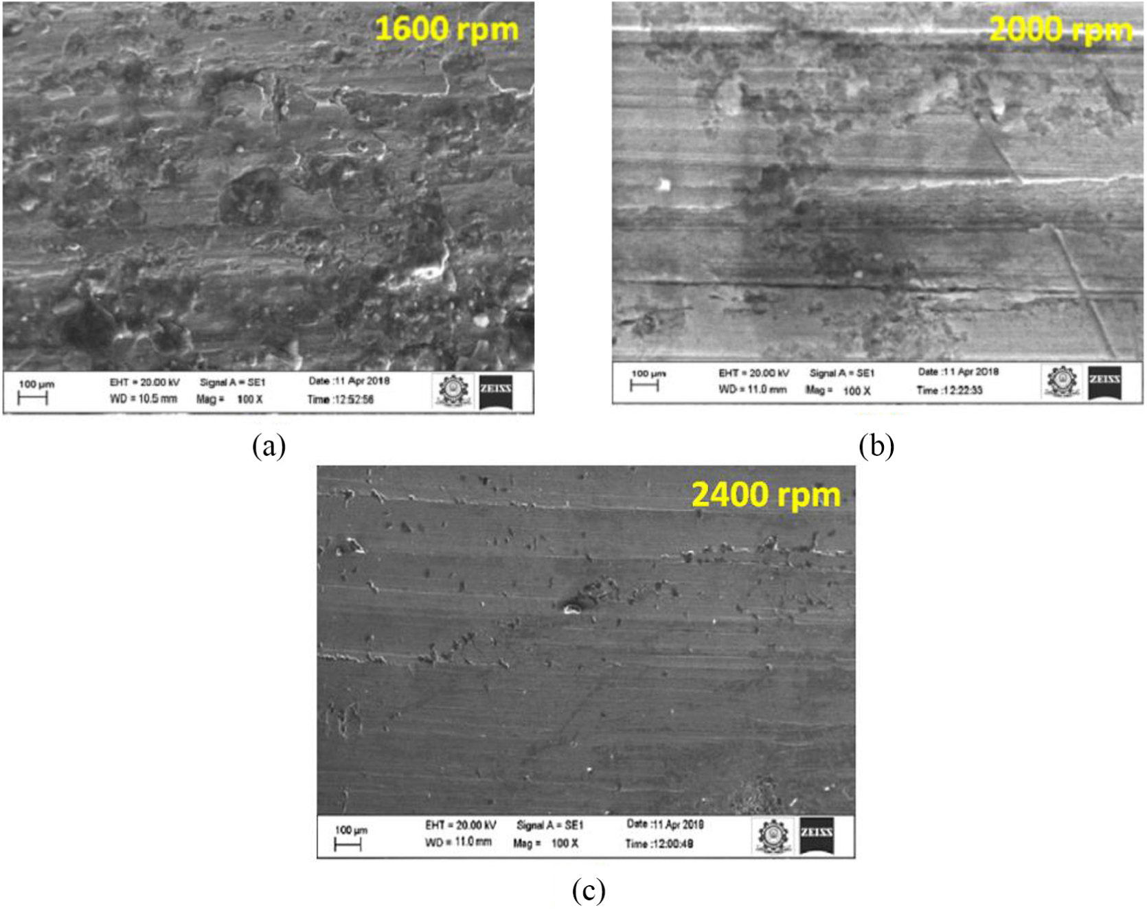
Effect of rotational speed on the microstructure at the tail-end region (a) at 1600 rpm (b) at 2000 rpm (c) at 2400 rpm
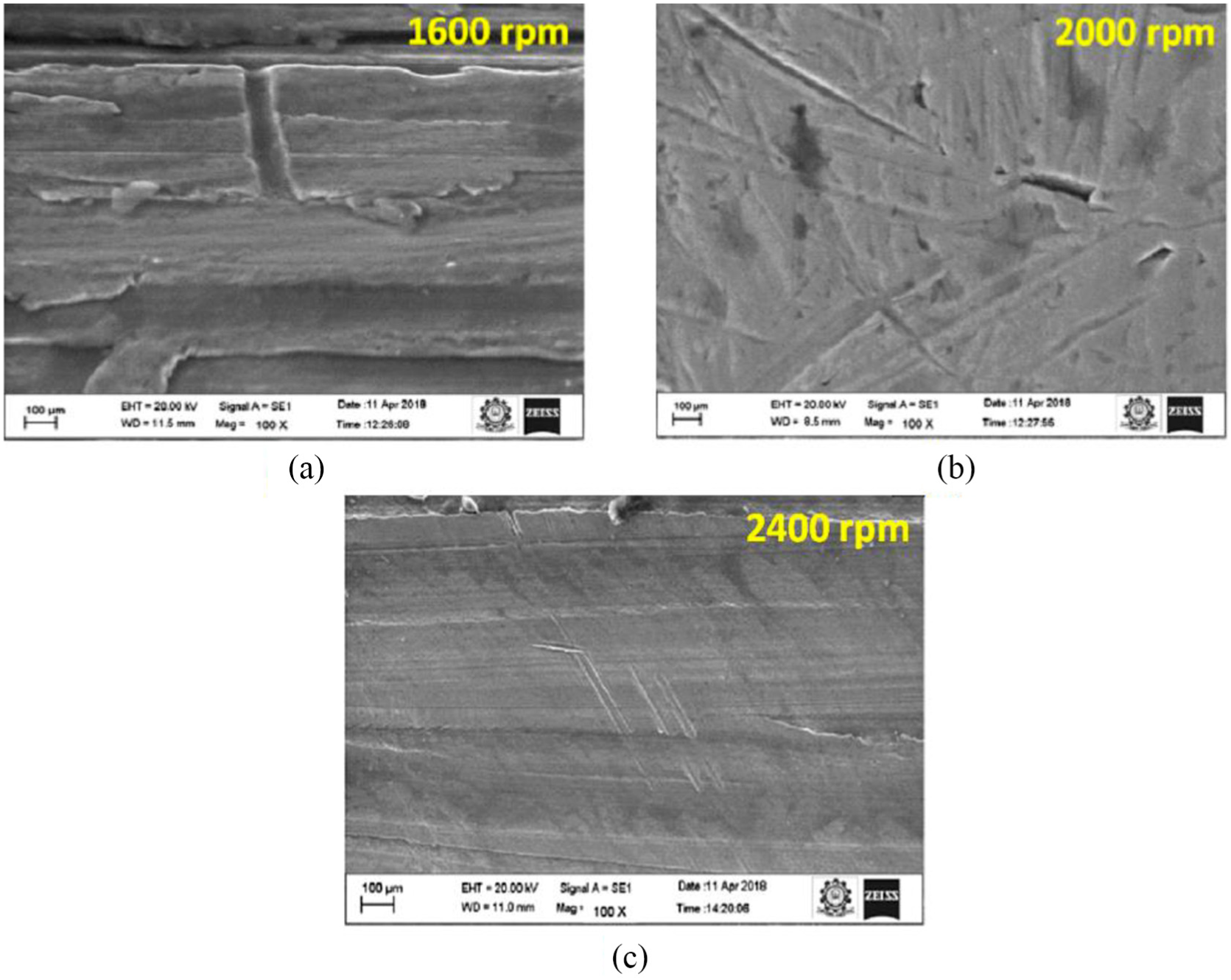
Effect of rotational speed on the Lüders band region
Then, the deformation bands are created due to the high stress and intermittent heterogeneous yielding. These bands are denoted as Lüders bands, which widely occurred in the drawing and stamping operations.23–25 This was displayed as an impression-like stretched-strain marks. Moreover, these discrete bands can be easily viewed by the naked eye as shown in Figure 12. Therefore, this region is named as Lüders band region (B). The above two regions, that is, tail and Lüders bands, are created by the application of axial force of thermal drill tool.
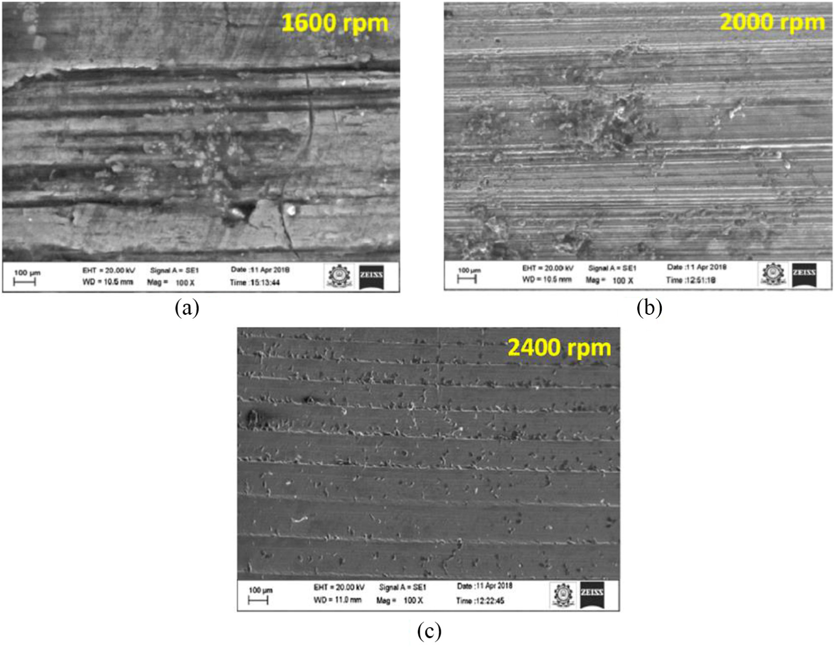
Effect of rotational speed on the microstructure at the Luders band region (a) at 1600 rpm (b) at 2000 rpm (c) at 2400 rpm.
The microstructures at the Lüders band region (B) formed for the different rotational speeds are shown in Figure 12. The microstructures in Figure 12(a) produced at 1600 r/min show the highest thickness Lüders band waves while the stirring action was created by the conical section of the thermal drilling tool. From the Figure 12(b), the more amount of smaller thickness Lüders band was identified during thermal drilling at 2000 r/min. These discrete bands are shown in similar to the smaller thickness scratched lines. The Lüders bands appeared in Figure 12(c) are similar to the river water flow pattern, which are produced at the rotational speed of 2400 r/min. Surface roughness values produced at this region are 2.132 µm (1600 r/min), 2.286 µm (2000 r/min) and 1.522 µm (2400 r/min). It can be found that the surface roughness varied and decreased on increasing the rotational speeds. Microhardness values obtained at this region are given in Table 3. In this region, the reference points (H3, H4 and H6) are used to provide the microhardness values. At 1600 r/min, the values of microhardness are varied from 163.7 to 169.5 HV, and similarly, at 2000 and 2400 r/min, those values varied from 139.3 to 162.6 HV and 131.1 to 156.8 HV, respectively. These results show that the microhardness values obtained in the Lüders band region are higher than the tail-end region.
Effect of rotational speed on the lower and upper critical region
Subsequently, the conical section of the tool pierces the galvanized steel completely and then the cylindrical section of tool initiates to enter into the workpiece. Therefore, the conical cavity shape was deformed to form a hole and then that hole was enlarged by the piercing of the cylindrical section which leads to form a bush-like shape at the end. Here, an application of force is switched over to force transmission. This region is named as the lower critical region (C). Moreover, the deformation in this lower critical section is typically uniform, and no stretched-strain marks are created due to high rate of heat generation. Then followed by this region, the upper critical region (D) is formed where the heat generation rate is very low.
Figures 13 and 14 show the microstructure at the lower critical region (C) and upper critical region (D) produced at the different rotational speeds. At 1600 r/min, the microstructures are appeared with poor surface quality such as small cavities and sticking of material. This defect has reduced the surface integrity of the thermal-drilled hole. However, the microstructure at the rotational speeds of 2000 and 2400 r/min demonstrates the improved surface quality compared with the performance at the rotational speed of 1600 r/min. Figure 14(c) shows the highest surface finish in the upper critical region which is produced at the rotational speed of 2400 r/min. Those results are confirmed by the surface roughness test at the lower and upper critical region. Surface roughness values measured at the lower critical region are 2.611 µm (1600 r/min), 2.448 µm (2000 r/min) and 1.764 µm (2400 r/min). Similarly, those values obtained at the upper critical region are 2.355 µm (1600 r/min), 1.689 µm (2000 r/min) and 1.451 µm (2400 r/min). Microhardness test values at the corresponding regions are given in Table 3. The values of microhardness in the lower critical region (from H6 to H8) are altered from 114.5 to 198.5 HV (1600 r/min), 176.8 to 183.4 HV (2000 r/min) and 168.2 to 181.8 HV (2400 r/min). Also, in the upper critical region (H9 to H11), values of microhardness are varied from 114.5 to 125.4 HV (1600 r/min), 103.6 to 114.4 HV (2000 r/min) and 102.2 to 108.2 HV (2400 r/min). For this region, the microhardness of the inner surface of holes is affected by the piercing action of the cylindrical section of the tool.
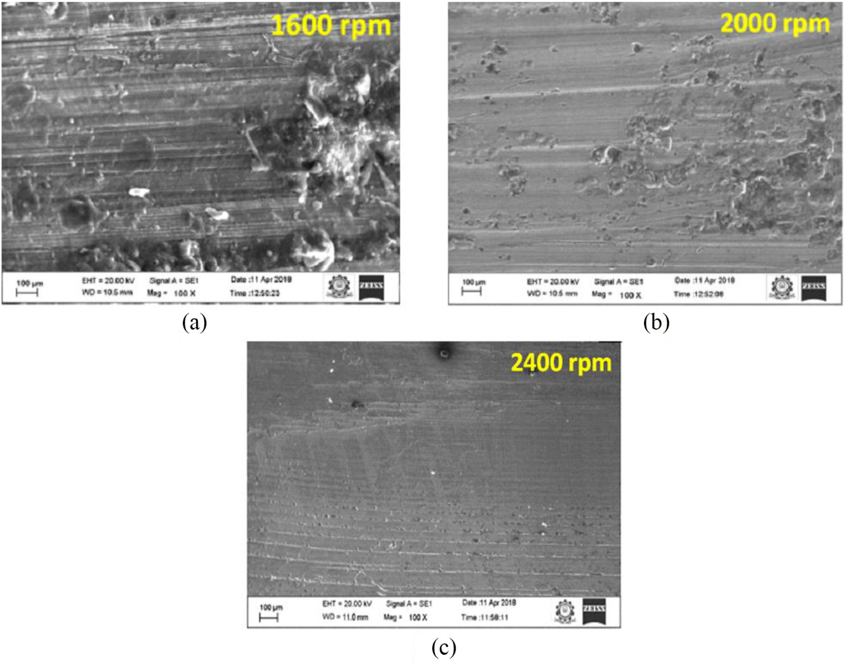
Effect of rotational speed on the microstructure at the lower critical region (a) at 1600 rpm (b) at 2000 rpm (c) at 2400 rpm.
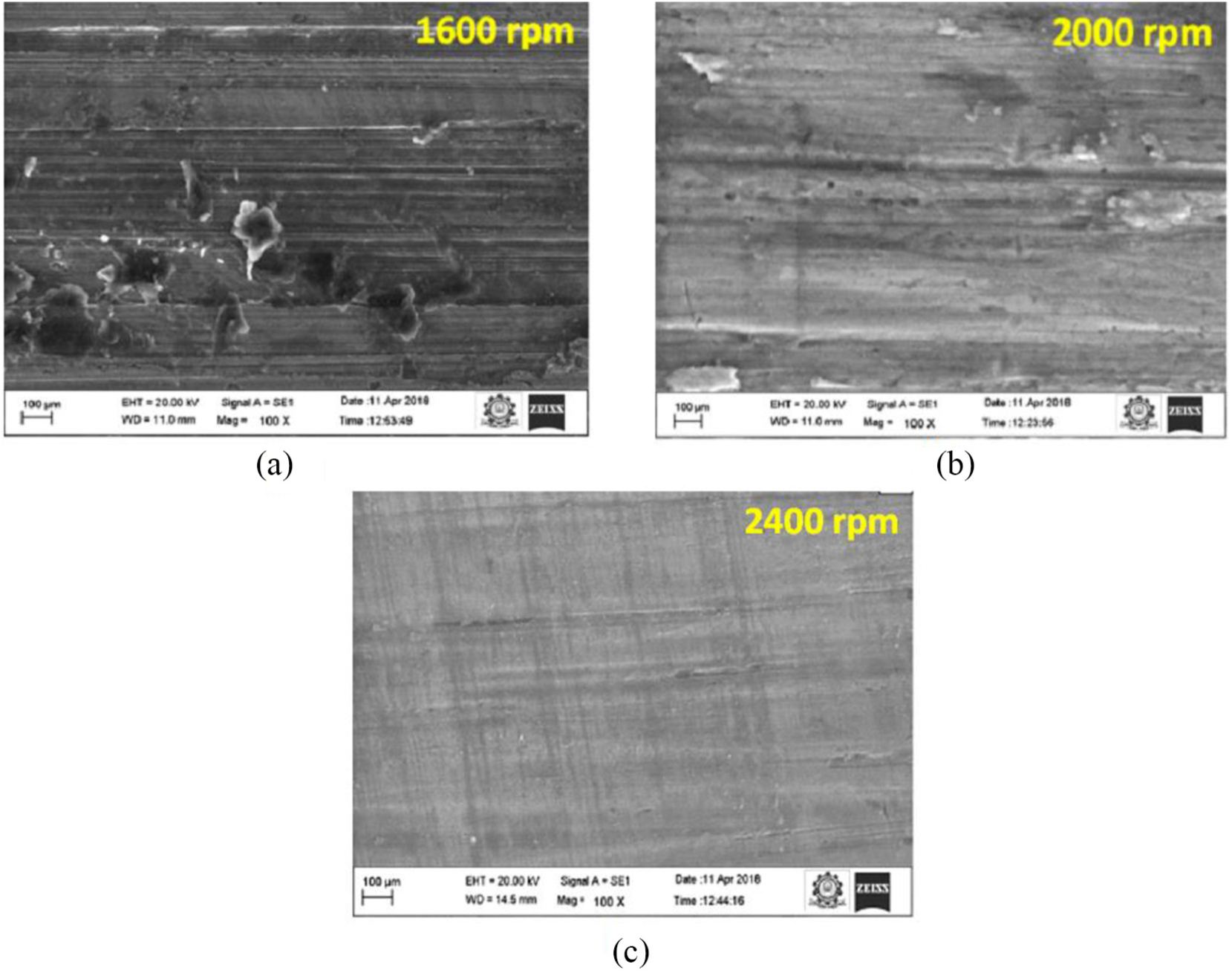
Effect of rotational speed on the microstructure at the upper critical region (a) at 1600 rpm (b) at 2000 rpm (c) at 2400 rpm.
Effect of rotational speed on the bending region
At the end of this region, the cylindrical section of the thermal drill is piercing the galvanized completely. At the same time, the shoulder section of tool starts to compress the unwanted burr present on the top surface of the drilled hole. Thus, this region is named as the bending region, where the shoulder region of the drill gives a forging force in a downward direction over the extended burr. Therefore, this burr material placed below the shoulder section of the tool is leveled. Finally, a boss or washer-like shape is formed on the top surface of the drilled hole. This boss is used to give the function like washer during fastening situations.
The microstructures at the bending region (E) for the different rotational speeds are shown in Figure 15. The bending region is formed by the compression action of the shoulder section of tool. Microstructures of bending region produced at the 2000 and 2400 r/min show the good appearance when compared with the microstructures obtained at 1600 r/min. The surface roughness could be evidenced for the alternation in the microstructures of the drilled hole at the bending region. Surface roughness at this region is 3.201 µm (1600 r/min), 2.411 µm (2000 r/min) and 1.642 µm (2400 r/min). Microhardness obtained at this region (H12, H13) varied from 136.6 to 139.6 HV (1600 r/min), 129.8 to 132.6 HV and 118.4 to 121.2 HV. Those properties are affected by the pressing action of the tool’s shoulder section.
Effect of rotational speed on the microstructure at the bending region (a) at 1600 rpm (b) at 2000 rpm (c) at 2400 rpm.
Thus the microstructure alterations were found at the different regions of bushing produced at the different rotational speeds such as 1600, 2000 and 2400 r/min as shown in Figures 11–15. When increasing rotational speed from 1600 to 2400 r/min, the amount of heat generation was greater, due to that the higher amount of friction was exhibited in between the tool and workpiece. This higher heat generation would soften the galvanized steel and increase the thermal drilling capability. Hence, the better surface finish of a thermal-drilled hole was produced at the rotational speed of 2400 r/min.
Conclusion
This study is carried out to investigate the influence of rotational speeds on bushing height, surface roughness, microhardness and microstructure in the thermal drilling of galvanized steel.
Increasing of rotational speed improves the formation of bushing height in the thermal drilling process. Moreover, at lower rotational speed, the heat generation is low, which leads to produce high axial force (1450 N). This axial force creates ruptures and petals on the outer edges of the holes.
When rotational speed increases from 1600 to 2400 r/min, high amount of thermal energy was created because of increase in friction at the interface of tool and workpiece. This high thermal energy makes softening of the galvanized steel and then improved the ability of thermal drilling. Therefore, the superior surface quality in the thermal-drilled hole was achieved.
The investigation of the microstructure of thermal-drilled galvanized steel confirmed a new result of Lüders bands marks which were formed in all the specimens because of high thermal stress and non-uniform yielding of galvanized steel material. Also, the microhardness values at the different locations of the thermal-drilled hole wall were found for all the samples.
Footnotes
Declaration of conflicting interests
The author(s) declared no potential conflicts of interest with respect to the research, authorship and/or publication of this article.
Funding
The author(s) received no financial support for the research, authorship and/or publication of this article.