
Abstract
Fourier model–based multi-probe-error-separation is an error separation method that is useful for precise measurement of the rotation error motion of spindles or roundness profile of rotating machine parts. However, it is not yet widely used, because it suffers from the critical problem of harmonic distortion. This study explores the phenomenon of harmonic distortion in detail and analytically clarifies the principles behind its occurrence. The position at which harmonic distortion occurs can be calculated exactly and easily using principles related not only to probe arrangement angles, but also to measurement conditions such as data length and undulation range of interest. Based on these principles, we propose multi-probe system design guidelines for the effective selection of probe arrangement angles and avoidance of harmonic distortion. The reliability and usability of the proposed design method are verified by simulation tests; stable multi-probe-error-separation can easily be achieved using the proposed design technique. We conduct experimental tests using a special measuring system based on four probes composed of two different probe arrangement sets and verify that this multi-probe-error-separation method can acquire rotation error motion or roundness profile precisely without harmonic distortion.
Keywords
Introduction
Machine elements with rotational motions—such as cylinders and spindles—are used throughout the manufacturing industry, and it is often necessary to measure the rotation error motion or roundness profile (form error) of rotating devices or workpieces to evaluate a machine’s rotation performance. A precision rotational device has unwanted 5-degree-of-freedom error motions primarily due to manufacturing, assembly, and other errors that depend on the operating environment. These can cause malfunctions, degrade performance, and reduce a device’s lifespan. Whereas, roundness evaluation is a crucial technique for precision machines because roundness in rotary workpieces such as mechanical seals and bearings can result in vibration which can negatively affect the performance of rotational motions. For these reasons, many researches have been studied for rotation error motion and roundness measurement techniques by various methods using non-tactile type sensing such as optical sensors and these are demanded ultra-high-precision measurement accuracy more and more.1–4
Rotation error motion or roundness measurements are generally performed using runout data. As shown in Figure 1, the runout data include not only rotation error motions, but also unwanted error signals from roundness and setting errors. Also opposite case, when the roundness is measured, rotation error motions and setting errors need to except. These unwanted signals degrade the accuracy of the rotation error motion measurements or roundness evaluations.5–8 Minimizing the effect of these unwanted signals, for rotation error motion measurement usually use masterpiece artifact because it can be ignored the roundness effects. Likewise, for roundness measurement, ultra-high-precision rotational devices are generally employed to minimize motion error uncertainty. Therefore, these precision measuring systems for rotation error motion or roundness are usually expensive and time-consuming.
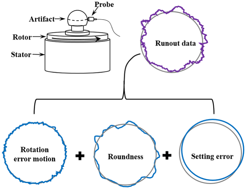
Runout data composed of various signals.
To solve this problem, several error separation techniques have been proposed, including Donaldson’s reversal method9–11 and multistep9,12–14 and multi-probe methods.9,14–17 Donaldson’s reversal error separation method requires an additional runout dataset, which is acquired after the same probes and artifact are precisely reversed using a specially designed device. This measurement process is complicated and time-consuming. Multistep error separation requires repeatedly acquiring runout datasets by rotating an artifact in equally spaced increments. Because of the difficulty of repeated resetting and measuring, this method is rarely used. Multi-probe-error-separation (MPES) methods use runout datasets acquired by three or more probes. However, no additional precision devices are required for resetting, and the datasets can be obtained with a single measurement procedure. This process can be conveniently applied to measure the rotation error motions of various rotating devices or the roundness of rotary workpieces in various environments. Among MPES methods, Fourier model–based MPES has attracted considerable attention in recent years because of its easy data collection process and high sampling rate.
Since Whitehouse 14 identified the problem of harmonic distortion in frequency-based MPES, many studies have attempted to solve it. Moore 18 observed that harmonic distortion becomes less severe for asymmetric probe arrangements. Zhang and Wang 19 and Zhang et al. 20 reported that harmonic distortion increases when the transfer coefficients decrease and introduced a method that uses more than three probes to avoid harmonic distortion. Furthermore, to avoid harmonic distortion, Gao et al. 21 developed a hybrid-multi-probe method that uses two displacement probes and one autocollimator, and Jansen et al. 22 presented a convenient solution using the least squares of the harmonic coefficients. Marsh et al. 23 found that poor choices of probe arrangement angles can lead to problems with small-valued transfer coefficients, even within a relatively narrow undulation range of interest. Although these studies alleviated harmonic distortion, the probe arrangement still depends on experimental results for minimizing the effects of harmonic distortion. In addition, a clear principle of occurrence of harmonic distortion has not been proved, and an exact solution to the stable probe arrangement design method has not been proposed based on a mathematical proof of the principle of harmonic distortion.
To solve this problem, Hale et al. 24 and Cappa et al. 25 proposed an evaluation function for determining the possibility of harmonic distortion using transfer coefficients to select statistically appropriate probe arrangement angles for a multi-probe system. Recently, Shi et al. 26 and Chen et al. 27 applied the determination method of probe arrangement angles using the evaluation function proposed by Cappa et al. 25 and reviewed the determined angles, and they predicted the occurrence positions of harmonic distortion. However, selected the probe arrangement angles by the proposed evaluation function value, the determination criterion (threshold value) is statistically determined, so it is not clarity. Therefore, this threshold value should be able to accommodate changes in various measurement conditions to accurately estimate safe conditions, but it is not clear in the above study. In addition, it is necessary to obtain the distribution map for the proposed evaluation function value at every design for selecting the probe arrangement angles, so it is consumed because the calculating time is long. Finally, the effects of measurement conditions such as data length and undulation range of interest have not been considered in various ways. Kim et al.28,29 and Lee and Lee, 30 our research team, proposed ideas for avoiding the harmonic distortion of MPES in previous studies that conducted clear mathematical analyses of the positions at which harmonic distortion occurs.
For this purpose, the exact relationship among the harmonic distortion positions, probe arrangement angles, and other measurement conditions (such as data length and undulation range of interest) is derived in this study. Thus, the principles of harmonic distortion are clarified using several measurement conditions for stable MPES, and guidelines for effective multi-probe system design are proposed for selecting probe arrangement angles applying the concept of the greatest common divisor (GCD) or prime factor. The usefulness and applicability of the derived relationship is verified through simulation tests. A validation experiment testing the guidelines is also performed using a measuring system that constructs four probes composed of two probe arrangement sets, designed for simultaneous measurement and comparison.
Principles of MPES
A typical MPES system is shown in Figure 2. Probes 2 and 3 are set apart from Probe 1 by probe arrangement angles


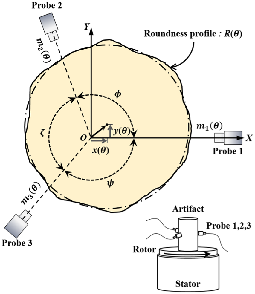
Probe arrangement for three-probe error separation.
The three runout datasets can be linearly combined into dataset
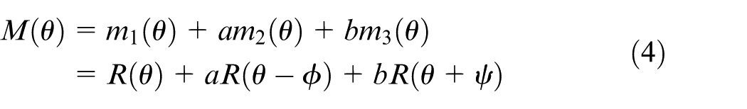
where
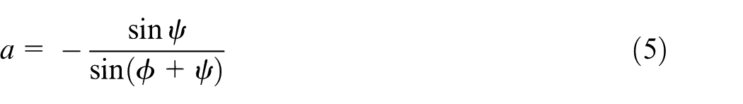
If
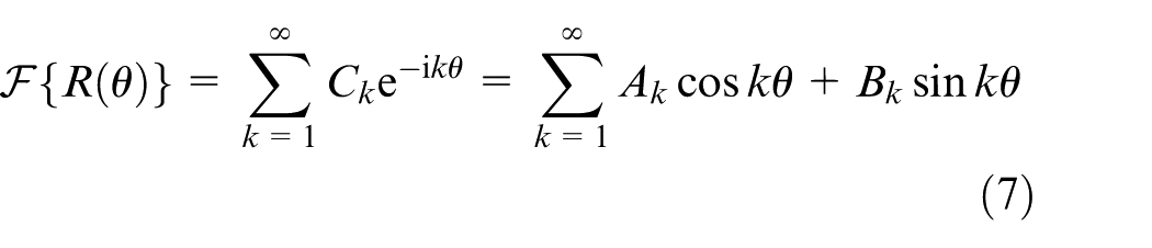
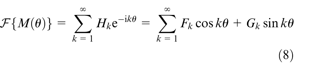
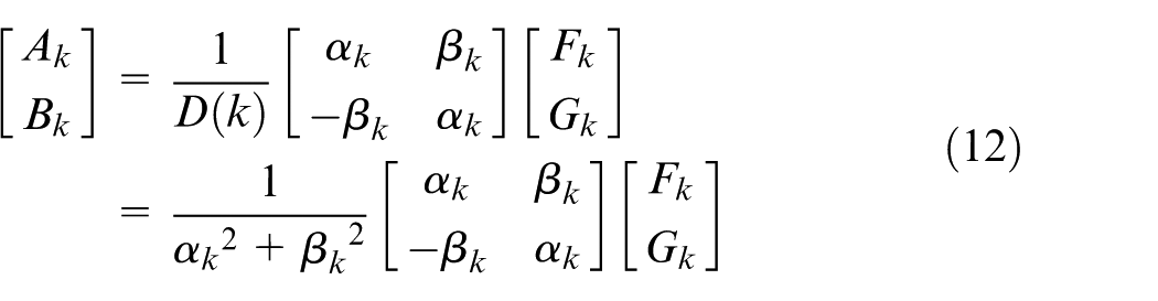
Considering equation (4), the relationships between the coefficients of equations (7) and (8) are represented as
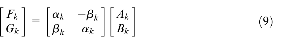
where


Hence, the Fourier coefficients
Finally, error signals
Probe arrangement for avoiding harmonic distortion
In this section, we derive equations for finding the positions of harmonic distortion and present guidelines for determining probe arrangement angles for a stable measurement system using MPES.
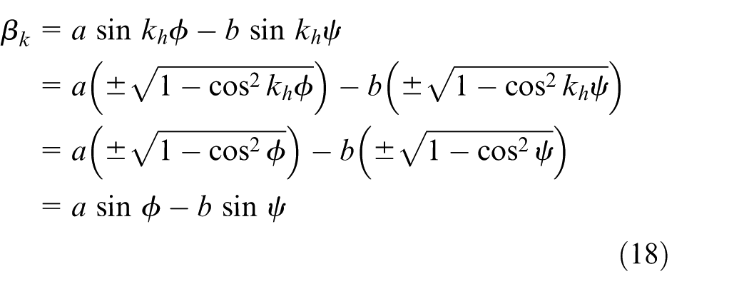
Both the coefficients


When this occurs, since the determinant in equation (12) also becomes zero,
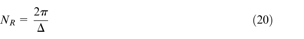
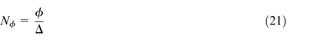
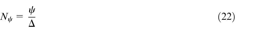
Undulation number (
)


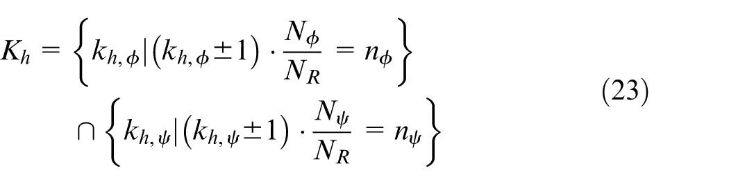
Thus, the undulation number set of
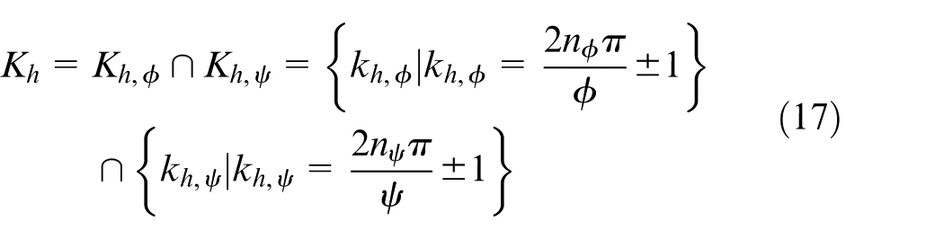
where
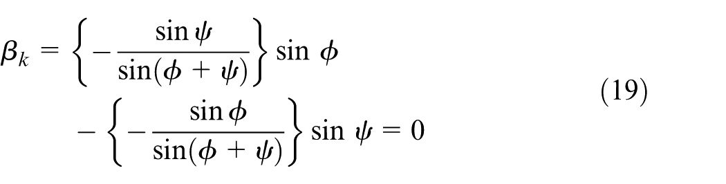
Furthermore,
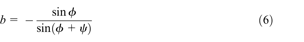
Applying the relationship from equations (5) and (6) to this result, we see that
Hence, the undulation number
For MPES to perform correctly, sampling must be performed by three probes at exactly the same sampling positions. Hence, when a measurement is made at a sample interval
Considering these probe arrangement condition, equation (17) can be rewritten as follows
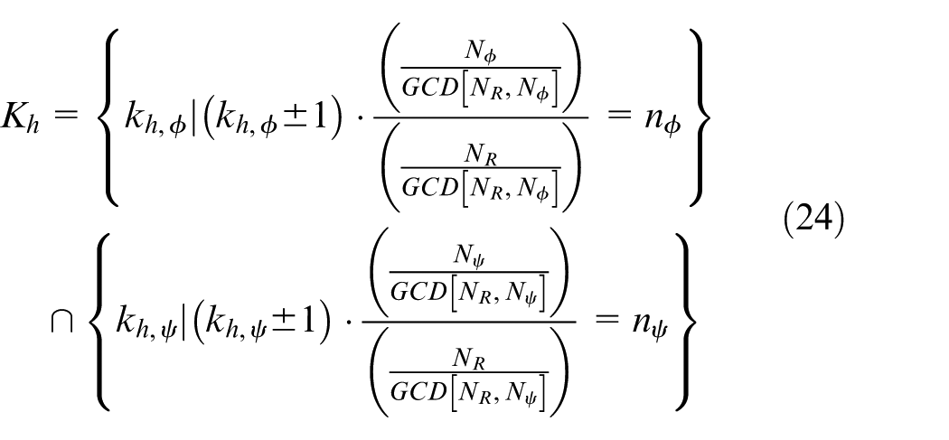
As the measurement conditions of

Selection of probe arrangement angles
and
Based on the results above, a probe arrangement design for avoiding harmonic distortion is proposed using the following steps:
Step 1: First, determine the undulation range of interest
Step 2: Choose the sampling rate by considering the undulation range of interest.
Step 3: List the candidate probe arrangement angles cases:
Step 4: Calculate the undulation number set
Step 5: Select the best candidate cases that satisfy equation (25).
Simulation for selecting probe arrangement angles
and
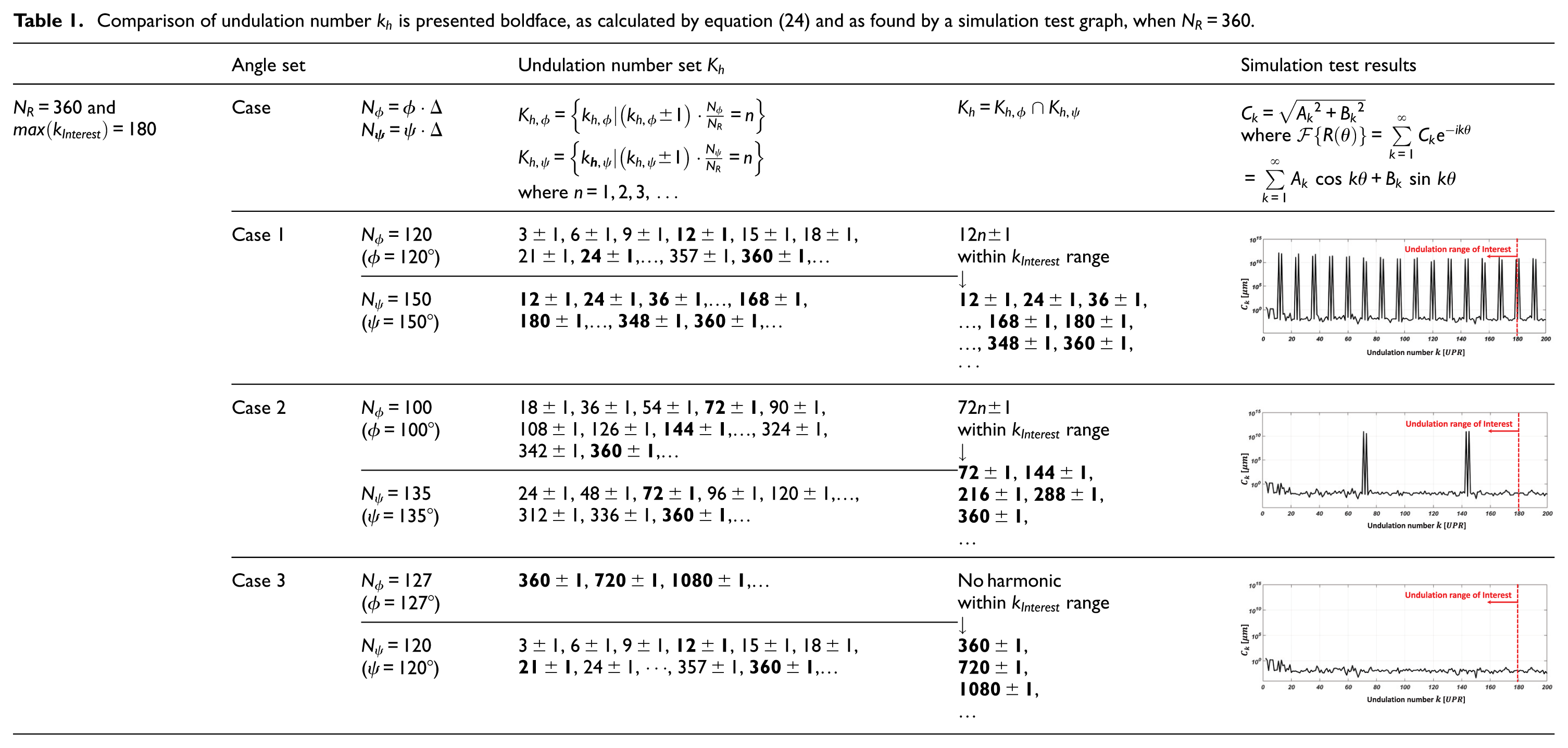
To accurately separate the cross-sectional shape error
As presented in Table 1, when
Comparison of undulation number
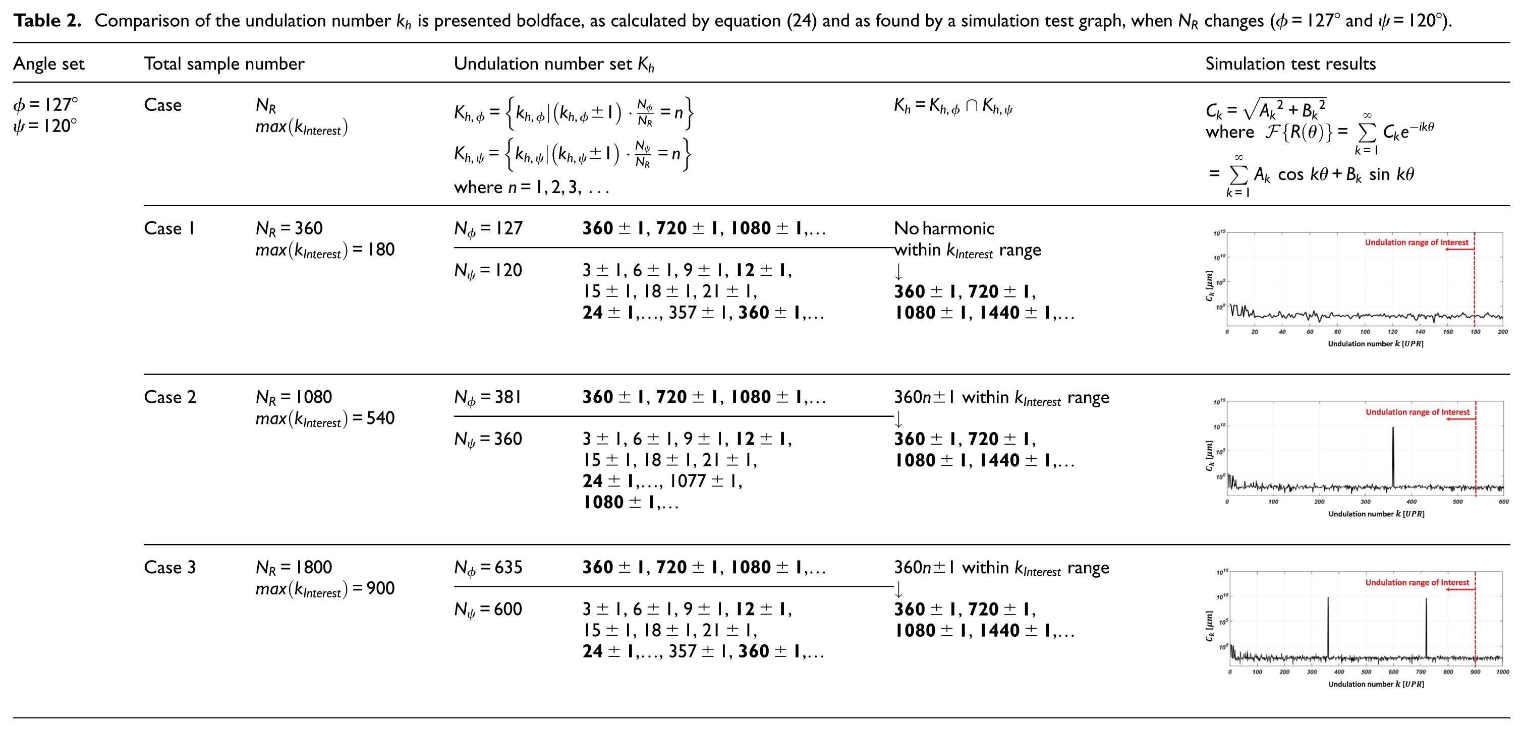
When the total sample number
Comparison of the undulation number
In measurement systems for monitoring the rotation error motion of large and ultra-precision rotating devices or for estimating the roundness of precision rotary workpieces, the range of angles in which probes can be mounted is often limited. In such cases, equations (24) and (25) are advantageous for accurately determining whether a measurement system is stable for each measurement condition. This contrasts with a design method that adopts conditions of comparative advantage based on statistical optimization.
For monitoring rotational devices or estimating rotary workpieces, the probe arrangement angle candidates marked by Areas 1, 2, and 3 in Figure 3 are generally considered to be the first mounting positions, when a multi-probe system is designed. A schematic design model of these typical probe mounting position examples is shown in Figures 4–6 upper part, respectively. System stability for Area 1 was investigated, and the results are shown in Figure 4, where
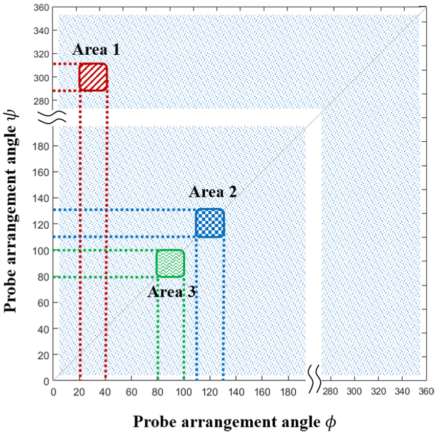
Searching candidate areas to design the multi-probe arrangement angles selected by considering typical probe mounting positions (
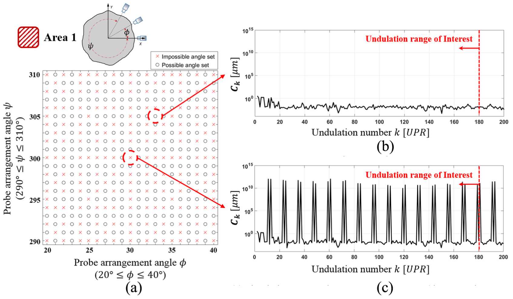
System stability of Area 1. (a) Target Area 1 (NR = 360), (b) simulation test result Nφ = 33, Nψ = 305 (φ = 33°, ψ = 305°), and (c) simulation test result Nφ = 30, Nψ = 300 (φ = 30°, ψ = 300°).
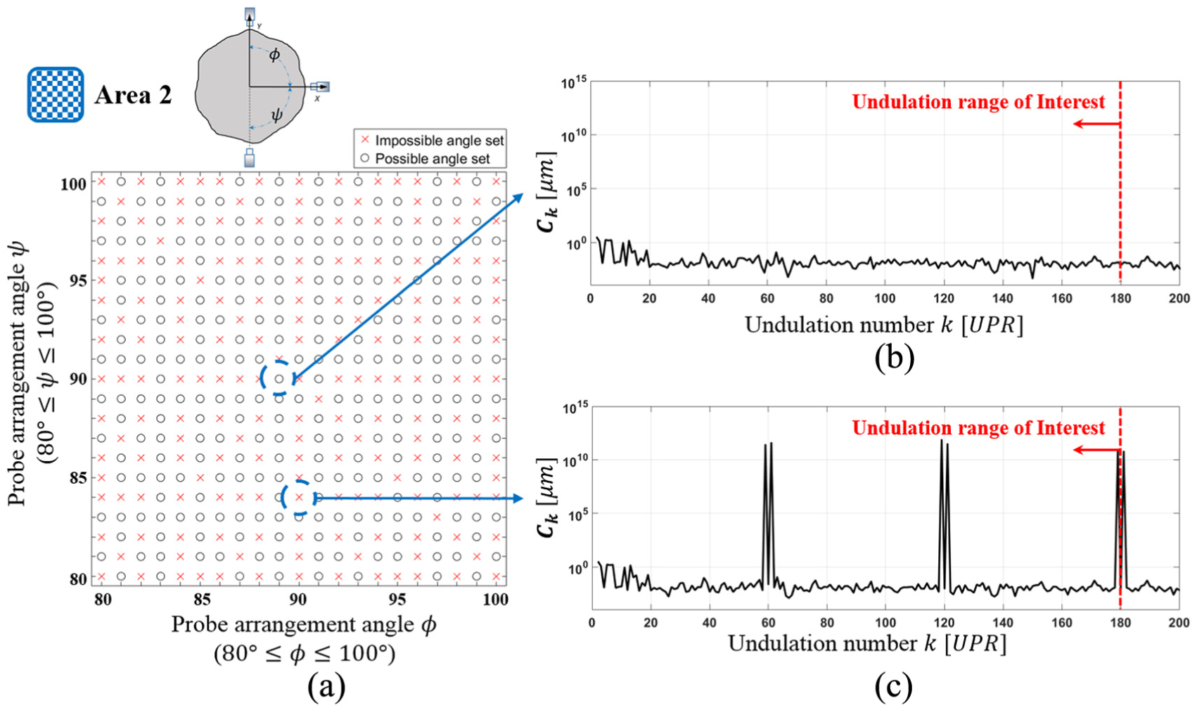
System stability of Area 2. (a) Target Area 2 (NR = 360), (b) simulation test result Nφ = 89, Nψ = 90 (φ = 89°, ψ = 90°), and (c) simulation test result Nφ = 90, Nψ = 84 (φ = 90°, ψ = 84°).
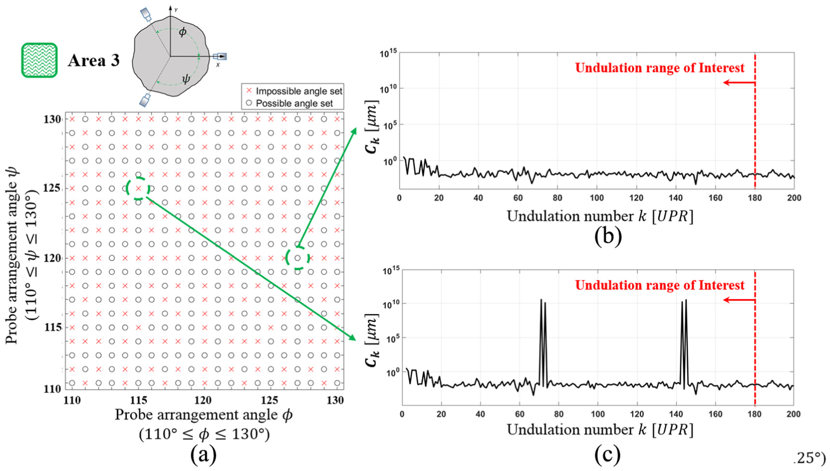
System stability of Area 3. (a) Target Area 3 (NR = 360), (b) simulation test result Nφ = 127, Nψ = 120 (φ = 127°, ψ = 120°), (c) simulation test result Nφ = 115, Nψ = 125 (φ = 115°, ψ = 125°).
As confirmed above, system stability can be exactly predicted using the proposed method for all cases in which the measurement conditions and probe arrangement angles are clearly given. This means that the system can be efficiently designed for stable MPES by applying the proposed method.
Testing and verification
In this section, we implement two tests to verify whether harmonic distortion can be safely avoided with the proposed design method, and whether the harmonic distortion occurs exactly at the expected undulation number
Test 1: To compare the results of two three-probe arrangements according to the established design guidelines.
Test 2: To compare the results of a three-probe arrangement designed to cause harmonic distortion and of a three-probe arrangement that follows the design guide.
To examine MPES without harmonic distortion, the reversal methods or an artifact with known cross-sectional profile data can be used to compare the results obtained using different measurement methods. However, it is difficult to measure the profile at the same cross-sectional outline with different measuring systems.
This study therefore required a testing system to simultaneously measure the same roundness with two different three-probe arrangement sets. Hence, a total of six probing units must be arranged on the same plane and at the intended angles, with each probing unit composed of a probe and a fine adjusting device. However, it is practically difficult to arrange the six probing units due to their form and size. To perform a test with the smallest number of probes, a four-probe testing system was designed, as shown in Figure 7(a). The system is composed of two different probe arrangements for MPES. It can measure the rotation error motion and artifact form error of one rotational device simultaneously. The probe arrangement angles for Tests 1 and 2 were determined based on the proposed design method such that the four probes were arranged in a restricted area and the two tests were implemented with minimal adjustment of the probe mounting positions.
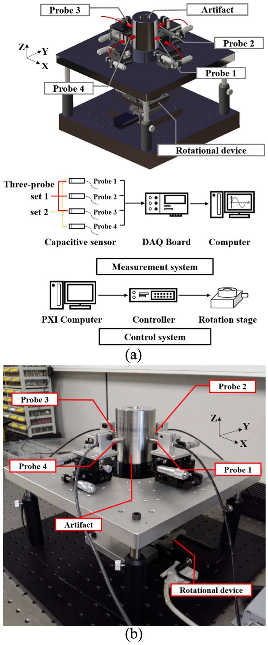
Multi-probe testing system with two different three-probe arrangement sets: (a) schematic of the measuring system and (b) experimental system setup.
Figure 7(b) shows the experimental system setup. To ensure MPES accuracy, a rotational device (M-037.PD; PI) was constructed, and an artifact with a diameter of 60 mm was mounted on the rotational device. The setup also consisted of four capacitive displacement sensors (MicroSense 2805, 1000 ± 500 μm, 3 nm resolution), an amplifier (MicroSense 8810), and a DAQ board (NI SCB-68). The runout data were obtained with a sampling rate of
To verify the performance of the multi-probe measuring system designed using the proposed guidelines, three cases of probe arrangements were selected according to the probe arrangement design method and two comparative tests were performed. Probe Arrangements 1 and 2 were stable without harmonic distortion, while Probe Arrangement 3 had unstable arrangement angles. Test 1, which makes a comparison between Probe Arrangements 1 and 2, is presented in section “Results of Test 1,” which shows comparison results of the runout dataset, roundness profile, and X-axis and Y-axis radial motion error. Section “Results of Test 2” presents an experiment performed to compare Probe Arrangements 1 and 3, which yielded results similar to Test 1.
Results of Test 1
Probe Arrangement 1 (
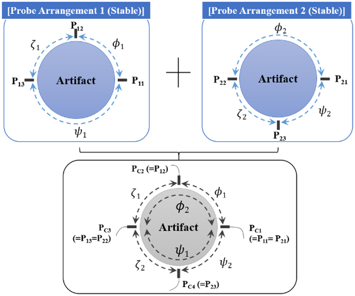
System configuration for Test 1 (
Runout datasets on the artifact attached to the rotational device were obtained simultaneously by the four probes, as shown in Figure 9(a). From the four runout data profiles, two runout datasets were acquired by the two probe arrangements: Probe Arrangements 1 and 2, as shown in Figure 9(b) and (c), respectively. For the two datasets from Probe Arrangements 1 and 2, MPES was implemented. The roundness and rotation error motion results are shown in Figure 10. The errors were calculated from the two datasets simultaneously measured on the same cross-sectional outline of an artifact by two probe arrangements. The deviation in the roundness, X-axis radial motion, and Y-axis radial motion errors were acquired from these results. The deviation of between results of Probe Arrangements 1 and 2 was less than about 6 nm peak-to-peak for the roundness, and the X- and Y-axis error deviations were less than about 3 and 8 nm, respectively. The results are in very close agreement, as intended.
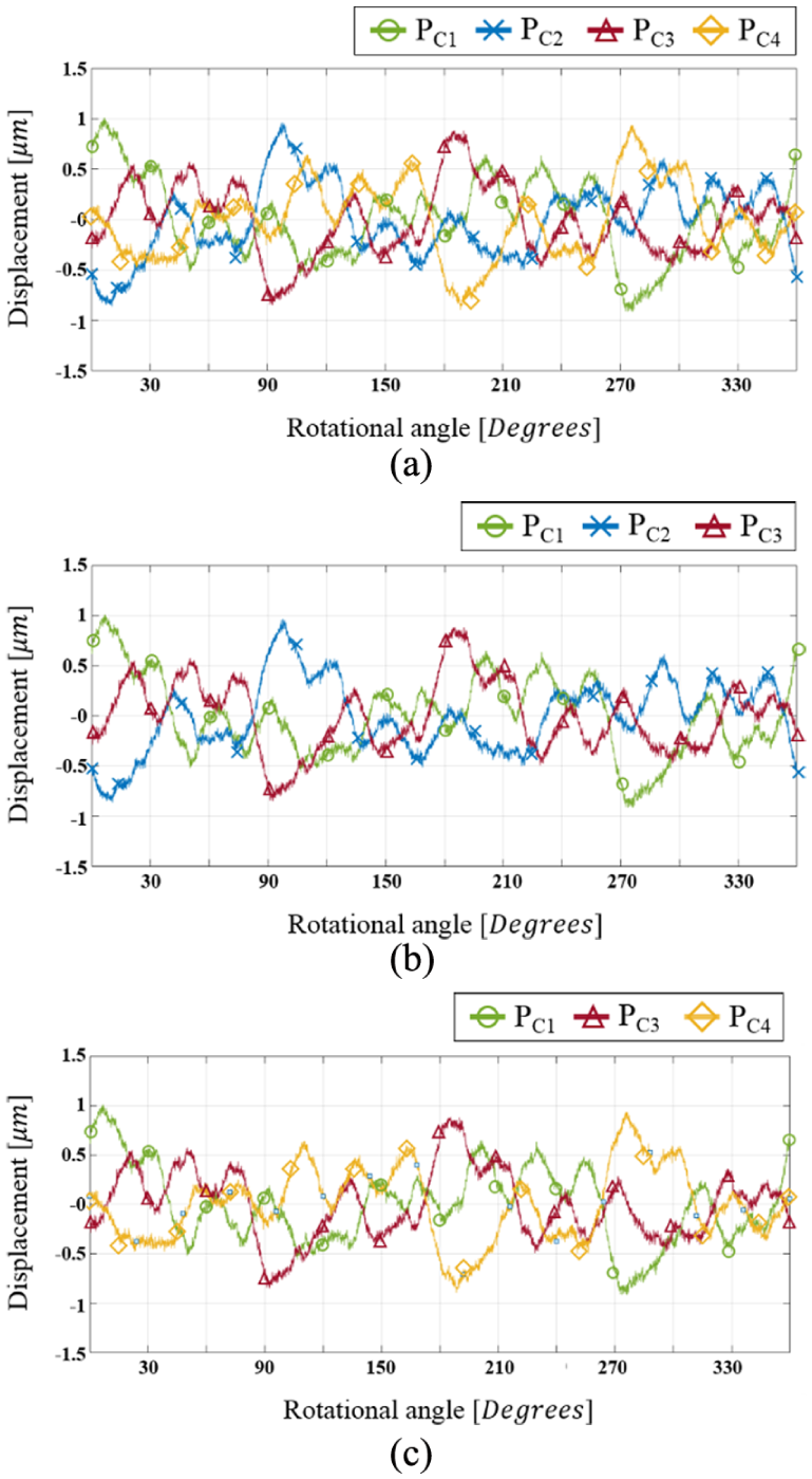
Runout datasets in Test 1. (a) Runout datasets obtained simultaneously by the four probes, (b) runout datasets of Probe Arrangement 1 (stable), and (c) runout datasets of Probe Arrangement 2 (stable).
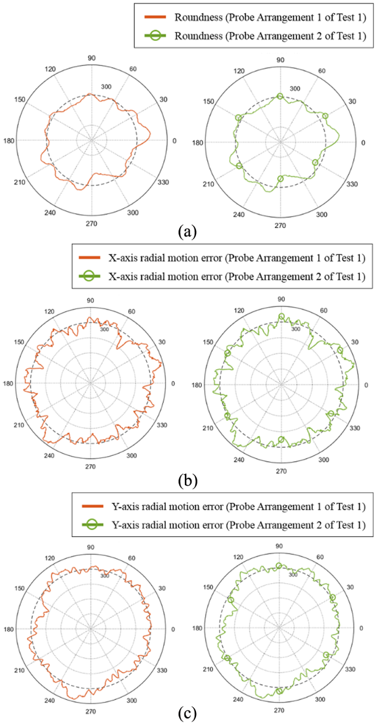
Roundness and rotation error motion signals separated by MPES from the runout datasets of Test 1. (a) Roundness profiles of Test 1 and the deviation between the results, (b) X-axis radial motion error of Test 1 and the deviation between the results, and (c) Y-axis radial motion error of Test 1 and the deviation between the results.
Results of Test 2
Probe Arrangement 1 as same in Test 1, which is expected to avoid harmonic distortion, and Probe Arrangement 3 (
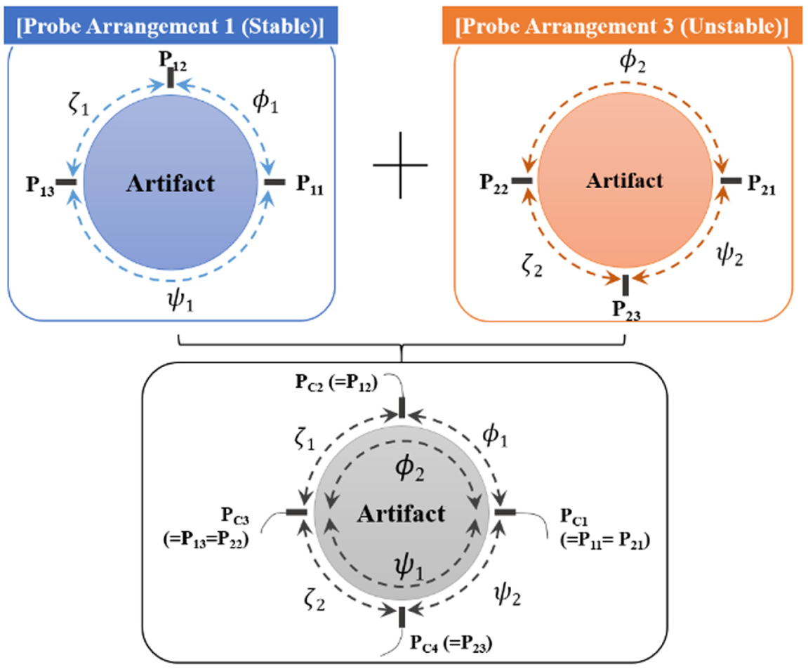
Experimental system configuration for Test 2 (
The measurement system reset up by fine adjustment of PC4 only about
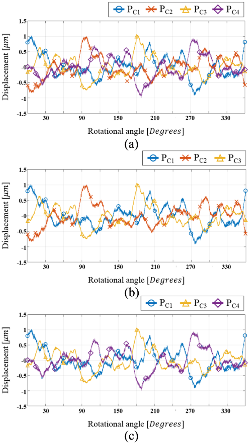
Runout datasets in Test 2. (a) Runout datasets obtained simultaneously by the four probes, (b) runout datasets of Probe Arrangement 1 (stable), and (c) runout datasets of Probe Arrangement 3 (unstable).
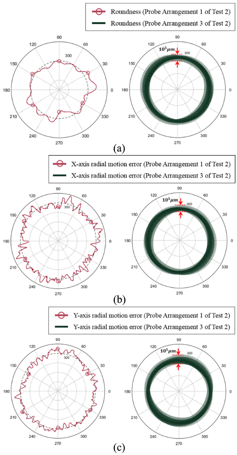
Roundness and rotation error motion signals separated by MPES from the runout datasets of Test 2. (a) Roundness profiles of Test 2 and the deviation between the results, (b) X-axis radial motion error of Test 2 and the deviation between the results, and (c) Y-axis radial motion error of Test 2 and the deviation between the results.
Measurement data from the unstable Probe Arrangement 3 were analyzed for harmonic distortion phenomena and compared with the predicted undulation number sets
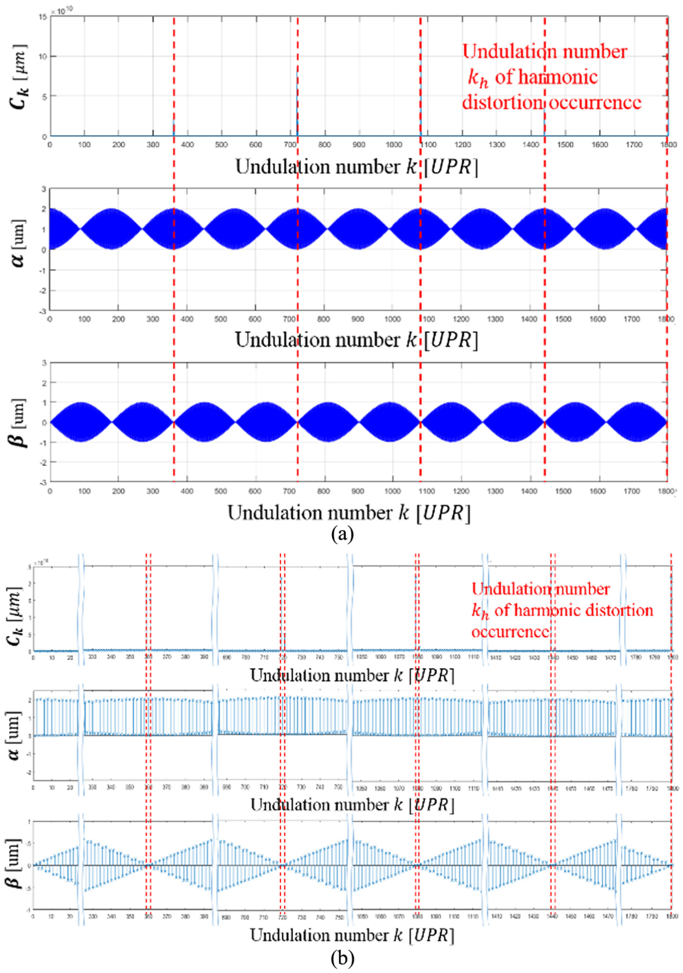
Comparison of
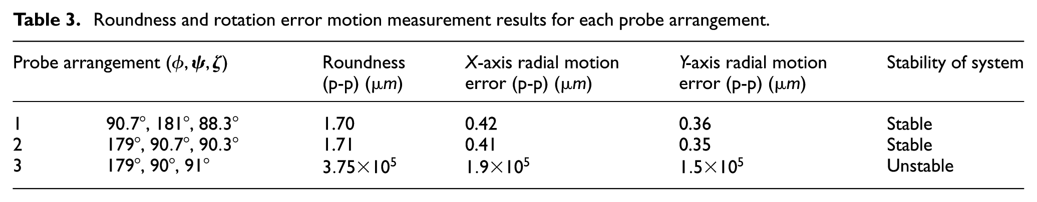
Roundness and rotation error motion measurement results for each probe arrangement.
Conclusion
This article proposed a probe arrangement design method of measuring form error of rotary workpieces and spindle error motion by applying Fourier model–based MPES. For this purpose, the principle of harmonic distortion, which is a critical problem for using MPES, was mathematically investigated, and it was verified to be generated by the relationship among the probe arrangement angles and measurement conditions such as sampling data numbers and undulation range of interest. Based on the proposed mathematical formulation, guidelines for multi-probe system design were proposed to effectively select probe arrangement angles to avoid harmonic distortion. The simulation and the results of measurement of the roundness and X-axis and Y-axis radial motion error confirmed the usefulness and stable of the probe arrangement design method for applying MPES. By applying this technology, it is possible to precisely and real-time monitoring of the rotating device driving state, and even the large diameter circular parts can accurately measure the cross-sectional shape. In addition, real-time measurement of rotational drive errors of multi-degrees of freedom will be possible through further studies.
Footnotes
Declaration of conflicting interests
The author(s) declared no potential conflicts of interest with respect to the research, authorship, and/or publication of this article.
Funding
The author(s) disclosed receipt of the following financial support for the research, authorship, and/or publication of this article: This paper was supported by the Individual Basic Science & Engineering Research Program (NRF-2014R1A1A2058185) funded by the National Research Foundation of Korea, and the Technology Innovation Program (Advanced Technology Center Program, 10045825) funded by the Ministry of Trade, Industry and Energy of Korea.