
Abstract
Herein, a precision measurement method is proposed to evaluate the radial, axial, and tilt error motions of rotating devices such as precision spindles. To improve the accuracy of the estimated multiple-degree-of-freedom error motion components, form error signals in the runout signals are separated and precompensated for before the calculation of the five-degrees-of-freedom error motion components. Fourier model-based multi probe error separation (MPES) techniques, which can prevent the occurrence of harmonic distortions, are applied to separate the form error signals. A three-probe method is applied to layers on the side surface of the cylindrical artifact, and a modified two-probe method is developed and applied to the upper surface. The radial, tilt, and axial error motions are calculated using the runout signals that do not contain the separated form error signals. The measurement system uses eight capacitive probes to detect the runout signals of the cylindrical artifact mounted at the center of the rotating device. To compare the proposed method with the five-probe-based conventional measuring method, an evaluation test simulation is conducted repeatedly five times. Results indicate that the proposed MPES method calculated the uncertainty using the deviation between the computed results from the existing and novel methods; additionally, the input signal in terms of the radial, tilt (layers 1 and 2), and axial error motions are
Keywords
Introduction
The performance of a precision device or manufacturing machine is highly affected by its rotating accuracy and various industry demands on on-machine measurement technology.1–7 For the precision evaluation of the rotational performance of a spindle, five-degrees-of-freedom (5-DOF) error motion components should be measured accurately using the runout data of the rotational parts.1,8–15 However, the runout data obtained from artifacts, which are widely used for the precision measurement of rotational error motions, contain form error signals of the artifacts’ surfaces. These undesired signals must be minimized or compensated. Many studies have been conducted to improve the measurement accuracy by eliminating the effects of form error signals.11,13–15
The existing five-probe based measuring method uses the output signal from each of the probes directly for the assessment of the 5-DOF error motion (x- and y-direction radial, x- and y-direction tilt, and z-direction axial error motions). The conventional five-probe spindle error motion measurement method is widely applied using ultrahigh precision reference artifacts such that the effect of the form error signals is negligible. However, this method is typically costly and sensitive to measuring environments. Moreover, when the required measuring accuracy is higher than the manufacturing accuracy of the reference artifact, this method cannot be used. Additionally, the system can only measure systematic errors. Its performance in measuring random errors is poor, limiting the overall measurement accuracy. Meanwhile, in an alternative method, the runout signal for the form error signal of the reference artifact can be compensated. In this method, the form error signals, previously measured using additional measurement equipment, are used as compensation signals.14,15
Several methods for efficiently separating the artifact’s form error signals from the runout signals can be used: reversal, 16 multistep,17,18 and multi probe methods.11–13,15,16,19–21 Compared with other methods, the multi probe method allows for real-time or on-machine measurements without additional precision devices. Furthermore, the multi probe method can easily separate the form error components using one of several calculation methods, such as the Fourier model method and the recursive sequential method. The Fourier model-based multi probe error separation (MPES) method can acquire measurement data at a high sampling rate. Additionally, it is barely affected by the zero-setting error of the probes. Despite these advantages, the Fourier model-based MPES method has not been widely used because it is susceptible to a harmonic distortion phenomenon that causes the calculated values to diverge considerably.19–22 Recently, an efficient design technique that prevents this phenomenon from occurring has been reported along with design guidelines for the problem. 23
In this study, a high-precision measurement technology to measure the 5-DOF rotational error motion was developed. The Fourier model-based MPES method was applied to separate the form error signals and calculate the radial, tilt, and axial error motion components. The three-probe method, which follows the design guidelines for avoiding harmonic distortions, was used to measure the two layers on the side surfaces of a cylindrical artifact to calculate the radial and tilt error motions. A modified two-probe method was developed and applied to the upper surface’s axial error motion. The radial, tilt, and axial error motions were calculated using the runout signals that were compensated for with the separated form error signals. The measurement system uses eight capacitive probes to detect the runout signals of the cylindrical artifact mounted at the center of the rotating device. This relatively low-cost technique is applicable to real-time on-machine or higher precision measurement systems, including those with low-precision artifacts. Using this technology, precision manufacturing equipment that has on-machine and real-time measurements applied, such as milling and turning machines, can be developed. In addition, it is feasible to apply the real-time compensation of rotational error motions that includes random errors in precision measuring equipment.
Spindle error motion measurement system
A typical 5-DOF rotational error motion of a spindle is shown in Figure 1. A precision measurement system was designed to measure the 5-DOF spindle error motion, as shown in Figure 2. The measuring system comprised a cylinder type artifact, rotary device, and eight probes, that is,
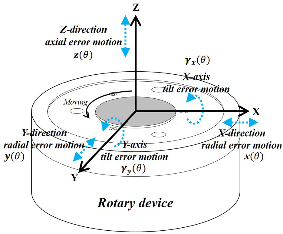
5-DOF spindle error motion.
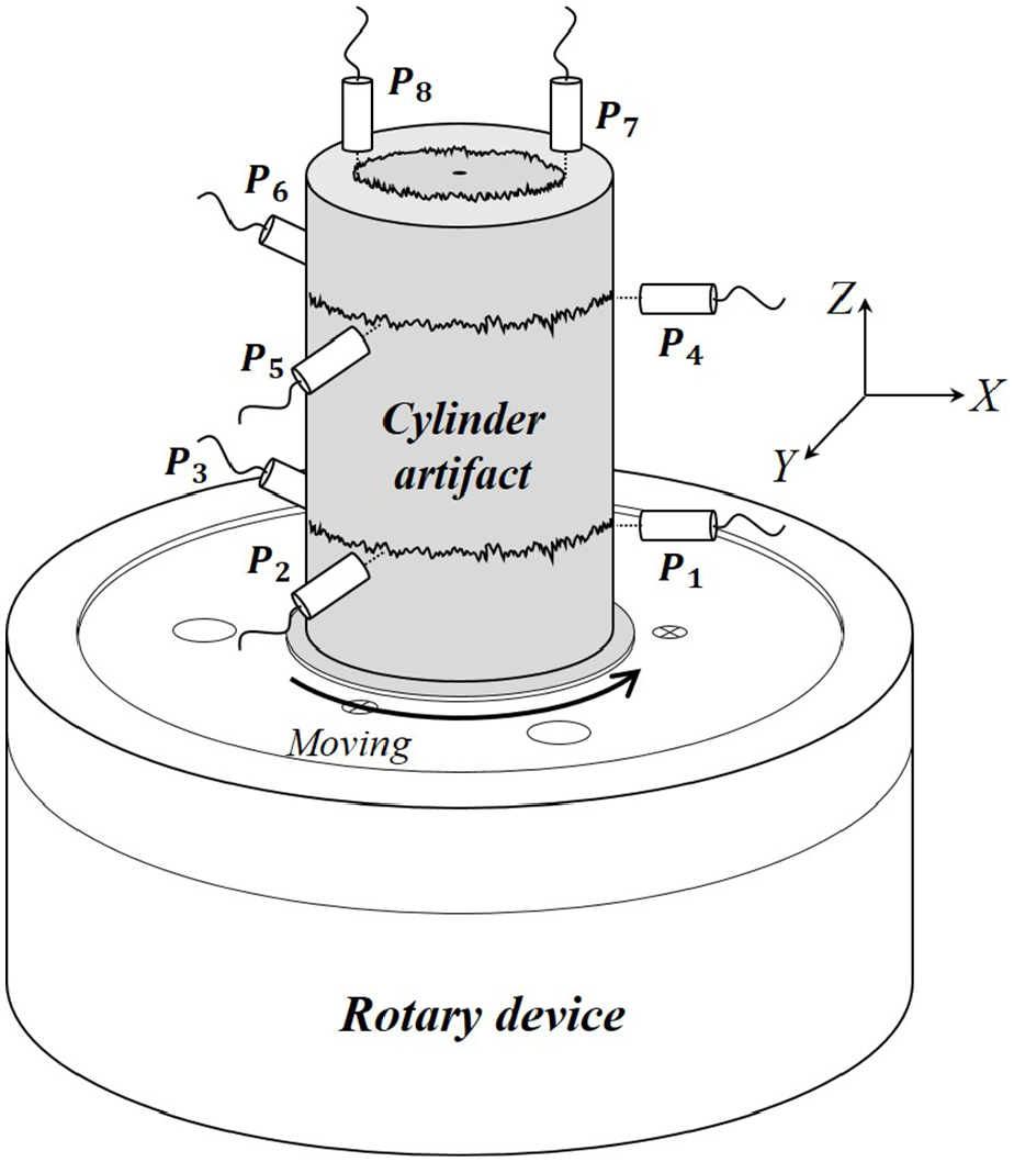
5-DOF error motion measurement system using multi probe error separation method.
To measure layers 1 and 2, two three-probe sets were placed on the side of the cylindrical surface to detect radial and tilt error motions in the X- and Y-directions. To measure layer 3, two probes were placed on the upper surface of the artifact to detect the Z-axial error motion. A schematic depicting the geometrical effects of the five types of error motions on the runout data of the probe sets in the three layers of the measurement system is shown in Figure 3.
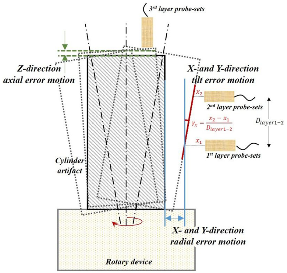
Schematic of three-layer measurement system for 5-DOF spindle error motion.
The conventional 5-DOF error motion measurement method calculates the error motion components using the runout data obtained from five probes, which are arranged as shown in Figure 4. The runout signals are acquired as mixed states of the spindle error motion signals, artifact form error signals, and setting errors, among others (Figure 5). Hence, the artifact form error component should be compensated for to measure the spindle error motion precisely. Generally, a method using a high-precision artifact is widely used to prevent the form error from affecting the cylindrical surface of the artifact. As mentioned above, such precision artifacts are expensive and difficult to manage, and they cannot be used for higher precision measurements. Many techniques have been developed to solve this problem. Among those techniques, the Fourier model-based MPES technique is an efficient method for preventing the error signal problem.
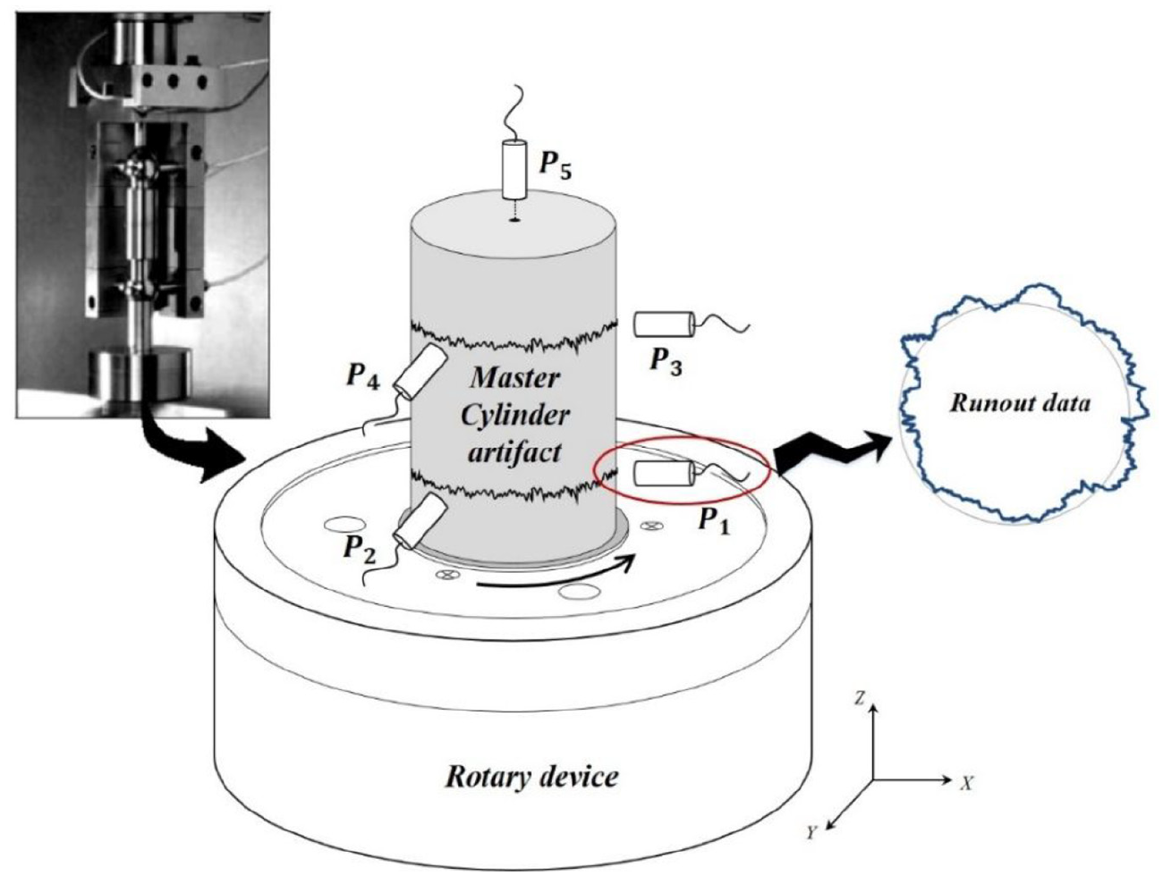
Conventional 5-DOF error motion measurement system. 14
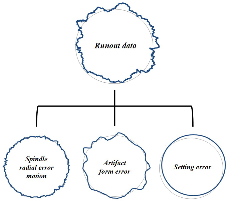
Runout data effected by various error types.
Principle of designed measurement system
The MPES method based on a 5-DOF rotational error motion measurement system was developed, as shown in Figure 6. This measurement system adopts two types of Fourier model-based MPES methods to compensate for the form error signal. Whereas the three-probe method shown in Figure 6(a) was applied to the measurement of layers 1 and 2 on the side surface of the artifact, the modified two-probe error separation method shown in Figure 6(b) was used for layer 3, which is on the upper surface.
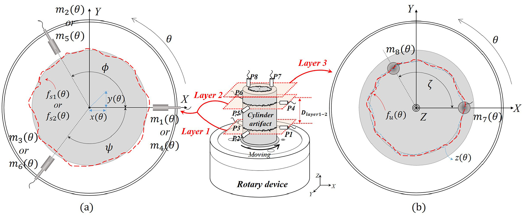
Multi probe measurement system: (a) for layers 1 and 2 and (b) for layer 3.
Fourier model-based three-probe error separation method
Form error separation on layer 1
To measure the error motion on layer 1, the form error signal of layer 1 must be separated The output data

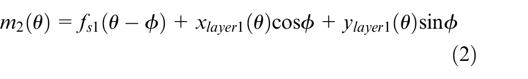

Subsequently, a linear combination
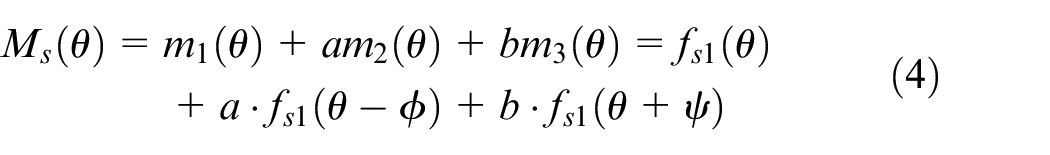
The rotational error motion components


The linear combination
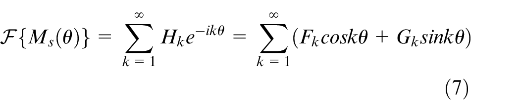
Meanwhile, the form error signal
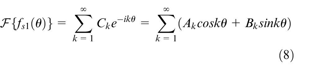
Considering equations (7) and (8), equation (4) can be written as equation (9):
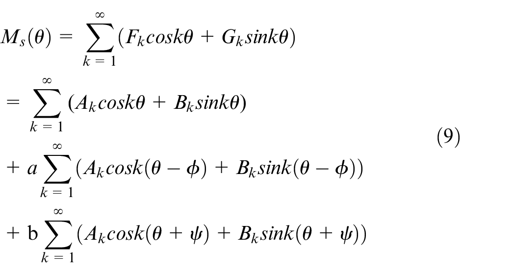
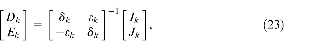
According to equation (9), the relation for the Fourier coefficients
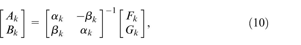
where


The form error signal
Radial error motion
According to equations (1)–(3), the error motions


Tilt error motion
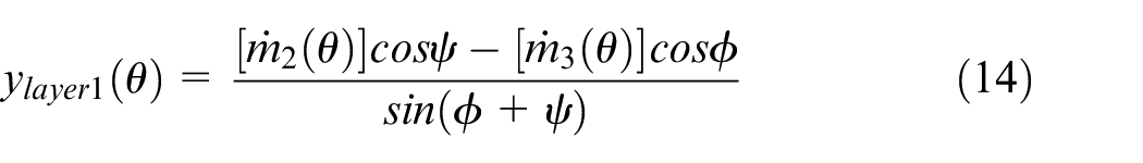
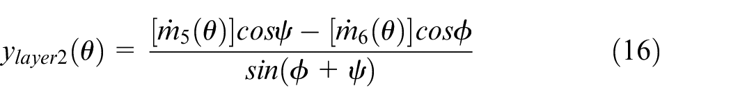
According to the geometric relations of the radial error components of layers 1 and 2, the tilt error motions

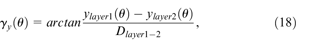
where
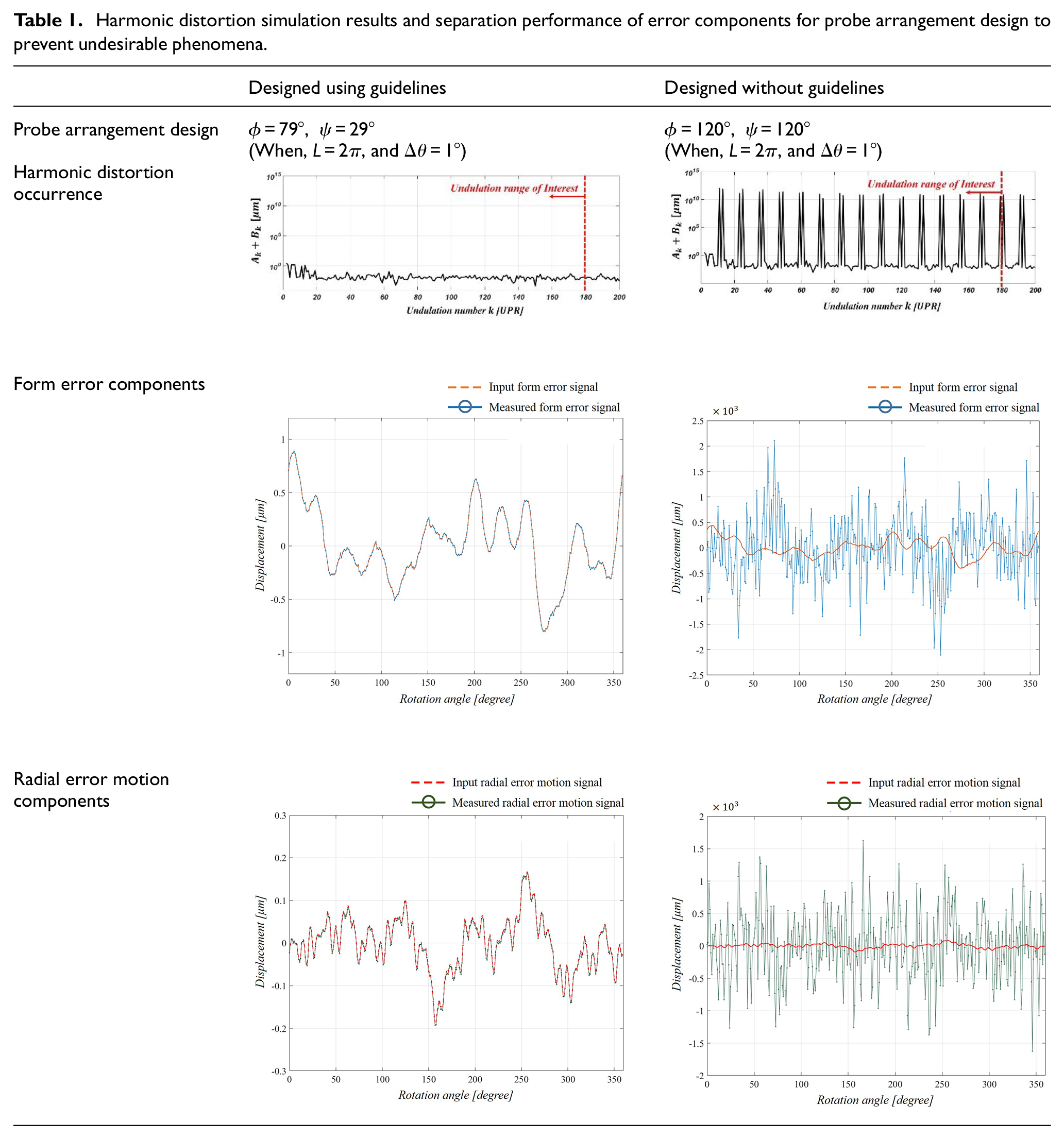
Probe arrangement for avoiding harmonic distortion
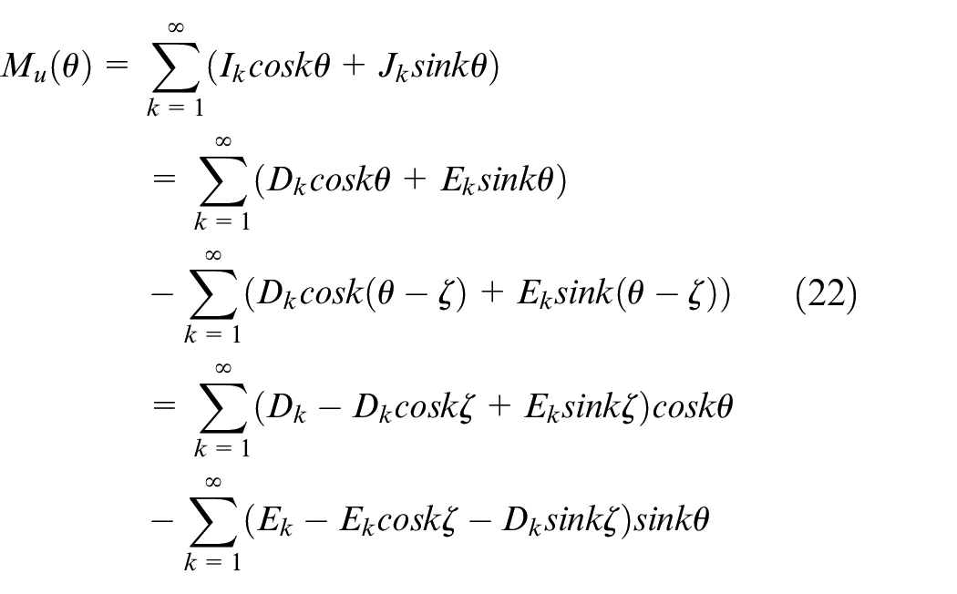
The harmonic distortion phenomenon is a fatal problem that causes critical errors when the Fourier model-based three-probe MPES method is applied. This problem is caused by the relations among
Both coefficients


When this occurs, because the determinant in equation (10) becomes zero as well,
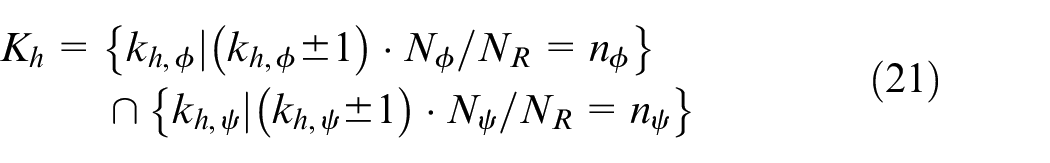
Finally, for stable error separation without harmonic distortion,

In this study, the probe arrangement angles were determined using the guidelines
Harmonic distortion simulation results and separation performance of error components for probe arrangement design to prevent undesirable phenomena.
Modified two-probe error separation method to measure axial error motion
As shown in Figure 6(b), two probes


where

Similar to the radial error motion separation process in section 3.1,
The Fourier coefficients
where


Similar to the previous three-probe method, the form error signal

Performance evaluation test
A detailed simulation was performed to test the proposed 5-DOF rotational error motion measurement method. First, the radial, tilt, and axial error motion signals as well as form error signals were prepared. The form error signals of layers 1–3 comprised both roundness and waviness components. Based on the geometric relationships of the measuring system shown in Figure 2, these generated data profiles were combined to form the runout data of the eight probes, as shown in Table 2.
Data generation for performance test.
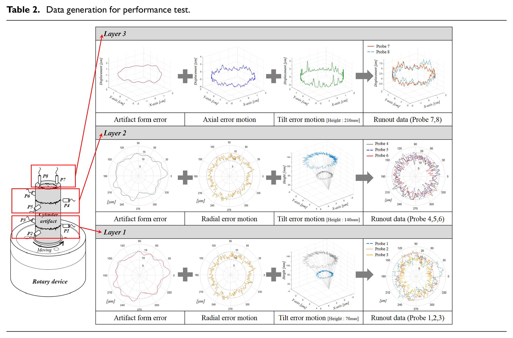
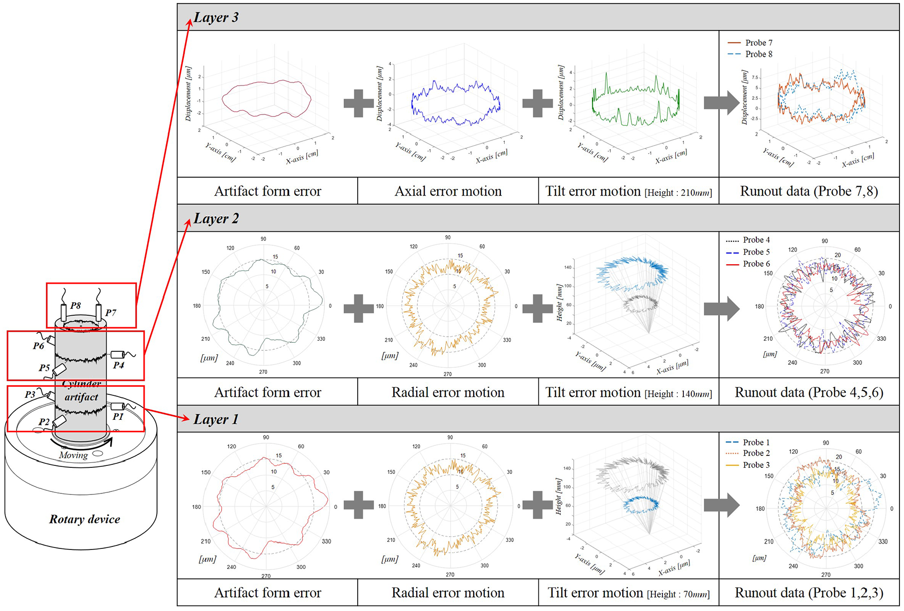
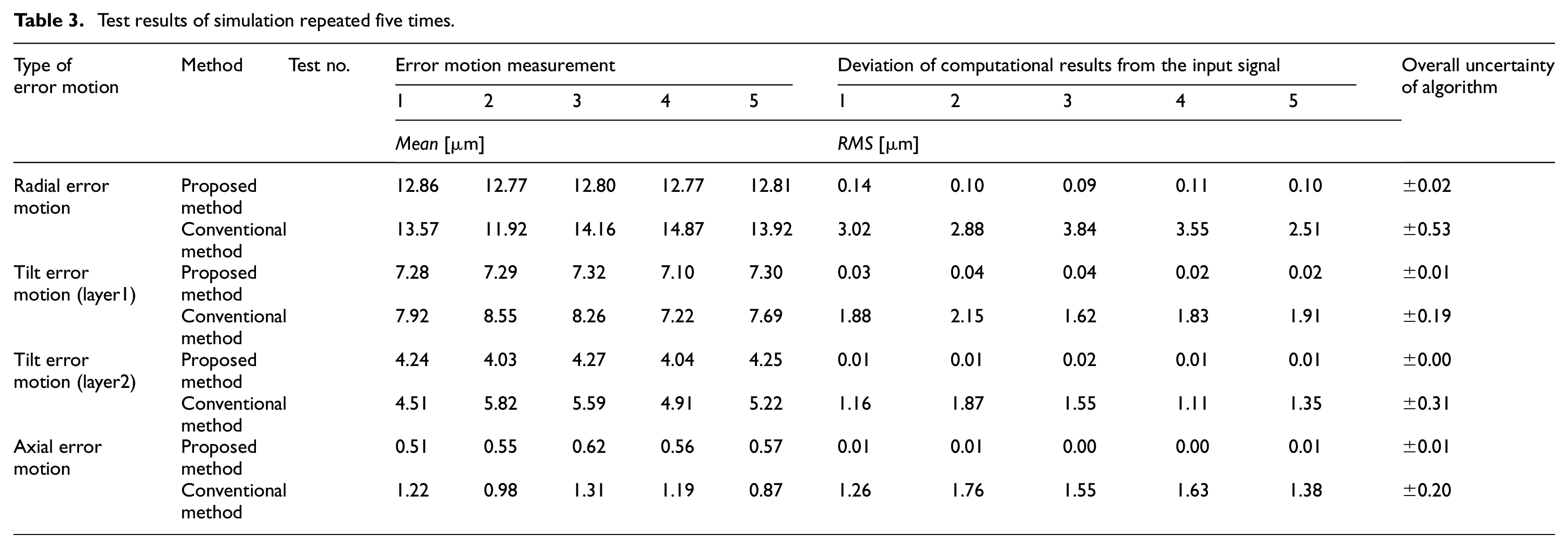
Figure 7 shows the proposed calculation process of the 5-DOF rotational error motion. The measurement tests were run 10 times. Using the runout data on Table 2, the typical results of the radial, tilt, and axial error motion components obtained using the proposed measuring method are shown in Figure 8. For comparison, the results obtained using the five-sensor based conventional measurement method without form error separation and compensation, as presented in Figure 4, are also shown in Figure 8. Owing to the effects of the form error signals, the results by the conventional method indicated a low measurement accuracy, that is, the input and measured signals differed significantly. Additionally, as the form error signals can be compensated efficiently, the results of the proposed method matched well with the input signals. The graph showing the displacement results from each layer in accordance with the tilt error motion is shown in Figure 8(b). It is clear that the displacement amplitude increased by the effects of the tilt error motion caused by the geometrical relationship arising from the measured heights of the probe. Figure 8 shows the first test results to represent the overall outcome from the five repetitions of the evaluation test, and the entire results are shown in Table 3. It was confirmed that the undesirable effects of the form error signals were successfully removed, and that the accuracy of the measured spindle error motion components improved.
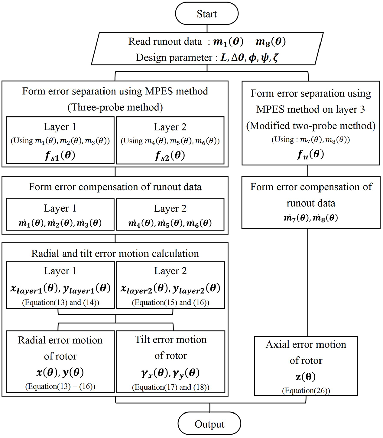
Calculation process of 5-DOF rotational error motion.
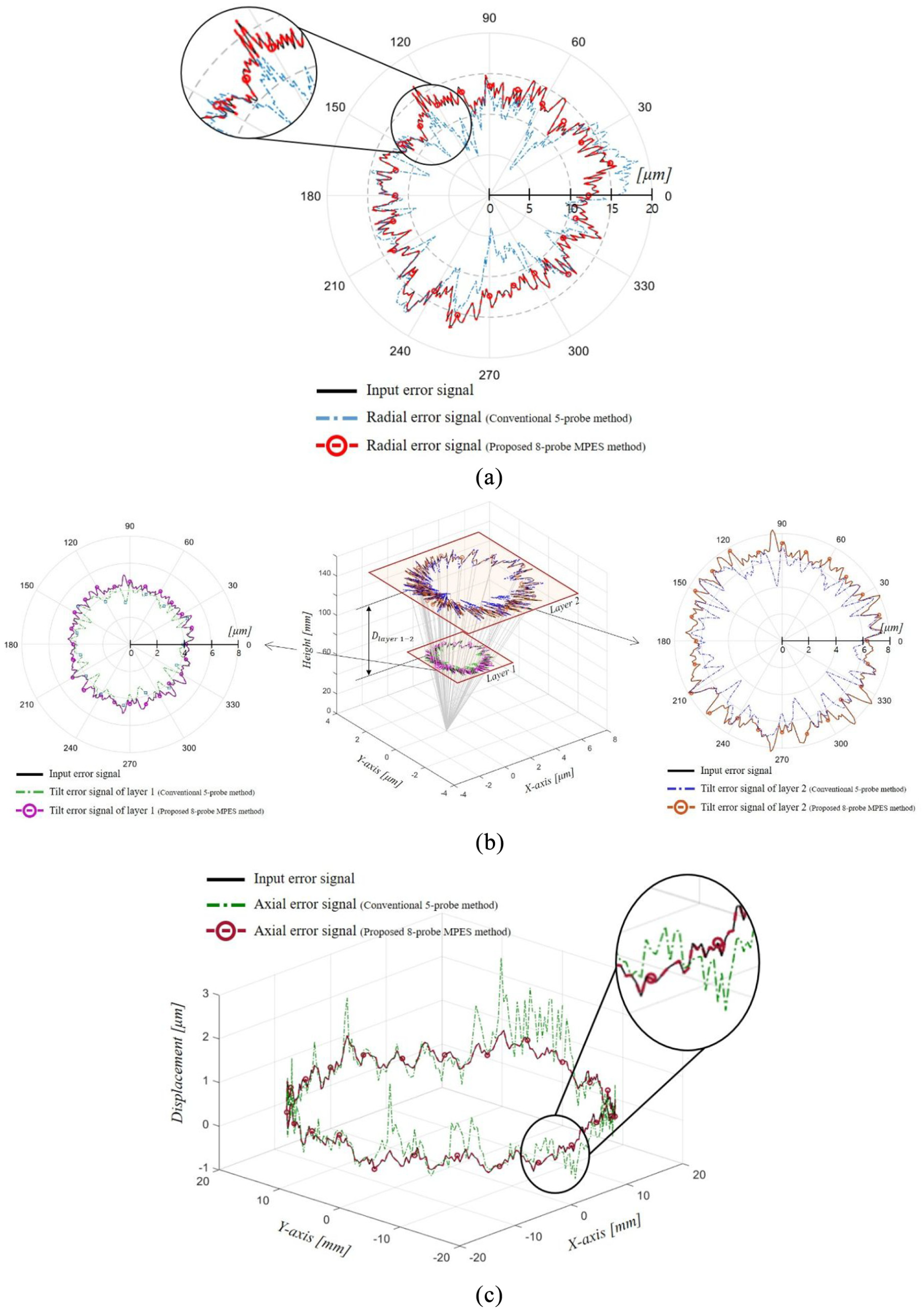
Comparison of test results between conventional and proposed methods with input generation data (first test results selected as representative outcome): (a) radial error motion, (b) tilt error motion, and (c) axial error motion.
Test results of simulation repeated five times.
Conclusion
A 5-DOF rotational error motion measurement method that can compensate for the form error signal in runout data was proposed. It was confirmed that the form error signals on the cylindrical surfaces or disk surfaces can be separated accurately using the improved MPES method, and the following system was designed.
A three-probe-system-based Fourier-model MPES method and an improved two-probe MPES method with issues arising from harmonic distortions resolved were developed.
The measurement system was designed as three layers to measure the 5-DOF spindle error motion, and eight sensors were implemented to apply each of the MPES methods.
To measure layers 1 and 2, two three-probe sets were placed on the side of the cylindrical surface to detect radial and tilt error motions in the X- and Y-directions. To measure layer 3, two probes were placed on the upper surface of the artifact to detect the Z-axial error motion.
To validate the system above, a simulation test was conducted, and the following results were obtained.
Input generation data with random errors, such as vibrations flowing into the data when the measurement system was applied, were produced and the runout-data sets from the geometrical relationship were used (see Table 2).
After generating the simulation input data, the simulation test was repeated five times, and the results from the conventional and proposed MPES methods were compared.
In the proposed MPES method, the uncertainty of the deviation of the computed results from the input signal from the radial, tilt (layers 1 and 2), and axial errors were calculated as
As the form error signals in the runout data can be compensated for efficiently, the measured performance of the error motion was significantly higher than that of the conventional method without the form error compensation. This technique is applicable to real-time on-machine or higher precision measurement systems with relatively low-cost and low-precision artifacts. Furthermore, the improved MPES method is expected to be applicable for measuring other similarly shaped mechanical parts.
Footnotes
Declaration of conflicting interests
The author(s) declared no potential conflicts of interest with respect to the research, authorship, and/or publication of this article.
Funding
The author(s) disclosed receipt of the following financial support for the research, authorship, and/or publication of this article: This paper was supported by the Individual Basic Science & Engineering Research Program (NRF-2017R1D1A1B0303379) funded by the National Research Foundation of Korea and the Individual Basic Science & Engineering Research Program (NRF-2020R1F1A1070803) funded by the National Research Foundation of Korea.