
Abstract
The high-precision part surfaces are usually finished by the corrective polishing to improve the surface form accuracy. This article proposes a new method to model and optimize the material removal in the polishing process. This method assumes that the material removal rate in polishing follows the Preston’s equation, and the material removal profile is obtained by integrating the material removal index along the tool path at each unit area of the tool/workpiece contact. The focus is on the effect of the sliding velocity on the material removal profile. Results indicate that the shape of the removal profile is affected by the angular spindle velocity, angular feed velocity and tool path radius. A series of simulation and practical polishing experiments were conducted to verify the proposed model. The tending gene of the removal profile is defined and derived. By using the principle of maximum tending gene, the material removal profile is optimized, which is helpful to plan the process parameter properly in polishing.
Introduction
Recently, the needs of free-form part surface have been widely recognized in optoelectronic and communication industries. The components with free-form surfaces not only occupy superior optical properties but also reduce the volume and the weight for the optical products. The fabrication of high-quality and precision part surface is becoming more and more stringent. 1 The manufacturing process for high-precision part surfaces typically involves a series of steps including generating, fine grinding, polishing and corrective polishing by the sub-aperture pad. 2 The corrective polishing process is usually regarded as a form of error compensation method for the part surface.3,4 As the final step in the fabrication, it is very important for the quality and the duration of the optical surface. Compared with the large polishing tool, the advantages of the sub-aperture tool for the surface error correction involve the high efficiency and adaptability to fit the curved surfaces. 5 Nowadays, many aspheric and off-axis optical lenses are completed by computer-controlled corrective polishing by the sub-aperture tool.6,7
In order to eliminate the form error of the part surface, the amount of the material removed by the polishing process has to be controllable. Thus, it is important to model and analyze the material removal during the polishing process in a scientific and quantitative manner. The ideal material removal profile in the contact region is with a central peak and a fairly rapid decrease to zero. 8 The orbital tool motion of the sub-aperture pad would generate the desired material removal profile, and it has been widely used by the computer-controlled polishing.9–13 Jones 11 investigated the material removal of the orbital motions of the square, round and hexagonal pads, and the tool selection process was developed for the efficient error correction. The characteristics of the material removal function is a key factor in determining the convergence rate of the error correction in the polishing process. The effects of the rotational speed ratio and the eccentricity ratio of the orbital motion on the removal function are discussed by Zhou et al., 12 and the optimized parameters have a high error correcting capability. According to the research by Chen et al., 13 as the removal profile converges toward Gaussian type, the convergence of the surface form error after polishing would be improved. The orbital tool motion has been successfully used to fabricate the large optical mirrors with high form accuracy. 14 However, the orbital motion of the polishing pad would lead to a relatively large processing area, thus the edge effect during the polishing, which refers to the nonlinear removal behavior as the tool runs over the edge of the part surface, is severe. 15 As a result, the orbital motion is only suitable to fabricate the large part surfaces. The polishing of the small surface components usually employs a rotational spindle at a specific angular velocity with a small spherical tool. When an elastic spherical tool pressed against the part surfaces, its shape would be compliant to the shape of the part surface in the contact region. Hertizian contact theory is widely used to model the contact size and the distribution of the pressure in the contact region.16–18 For the polishing process with a spherical tool, a small normal force corresponds to a small size of the contact region, which would result in low efficiency. 19 On the other hand, although the large normal force would enlarge the size of contact, the pressure in the contact region also increases, which would damage the surface easily and lead to severe tool wear. For the part surface of medium size, it is not very stable to polish by a spherical tool. Thus, there is a need for a stable and time-efficient finishing method capable of polishing the medium-size part surfaces.
According to the literature review above, it can be seen that the material removal during the polishing is largely determined by the motion pattern of the polishing tool and the corresponding process parameters. Reasonable motion pattern and process parameters would make the material removal during the polishing easy to control and speed up the convergence of the surface error. In this article, a new polishing system of a biaxial rotary motion is developed to polish the part surface of the medium size. The material removal during the polishing process is modeled based on the Preston’s equation. Especially, the effects of the sliding velocity (includes the effects of the angular feed velocity, the angular spindle velocity and the polishing path radius) on the material removal profile are discussed, and the optimization strategy for the planning of the process parameters is given to obtain the optimal removal profile with a central peak. The polishing experiments were conducted on the polishing system to verify the proposed model.
Material removal model in polishing
As shown in Figure 1, when the polishing tool presses on the part surface under a normal force, a certain area is formed by the contact between the polishing tool and the part surface, within which the material removal takes place. Based on the Preston’s equation, Fan et al.20–22 indicate that the material removal in the contact region can be described by the material removal profile orthogonal to the polishing path and the material removal profile can be calculated by
where MRIh/l is the material removal index which is defined as the unit depth of material removal per unit length of the tool path, L1 and L2 correspond to the starting and the end point of the polishing belt L, pc and vs correspond to the contact pressure and relative sliding velocity at H, and va is the feed rate.
(a) Graphical illustration of material removal in the contact region. (b) Schematic of material removal index.
For the sub-aperture pad polishes along the circular path as indicated in Figure 1, the infinitesimal distance dl can be expressed by

The material removal depth at H may be calculated by integrating MRIh/l along the circle centered at O with radius ρ in the contact region, which gives
where φ1 and φ2 are the polar angles of point L1 and L2 respectively.
In the polishing, the sub-aperture pad is compliant. If the curvature radius of the surface at the point P is very large compared to the size of the sub-aperture pad Rp, the soft pad may contact with the surface thoroughly. As shown in Figure 1, the contact region is a circle with radius Rp and the average contact pressure can be approximated as
where Fn is the normal force on the pad.
The relative sliding velocity in the contact region is composed by the sliding velocity due to the spindle rotation and the feed velocity along the tool path. In Figure 2, M(x, y) is an arbitrary point within the contact circle. The sliding velocity due to the spindle rotation at M is vm and the feed velocity at M is va. Thus, the relative sliding velocity at M can be expressed by the composition of vm and va, which gives
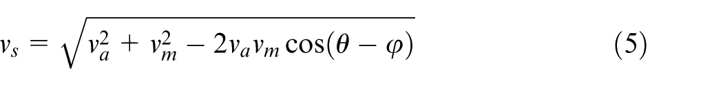
The sliding velocity due to the spindle rotation can be expressed by

where wp is the spindle angular velocity. The feed velocity around O at M is given by

where wq is the angular feed velocity for the tool moving around O and ρ is the distance from M to O. Substitution of equations (6) and (7) into equation (5) yields
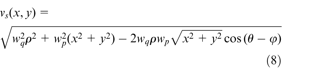
For the convenience of further discussion, the coordinate frame XOY is established at the curvature center O such that the Y direction is parallel to the y direction, as indicated in Figure 2. Transforming M(x, y) into the frame XOY by the polar form needs the coordinate transformation as follows
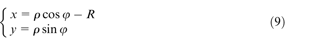
By substituting equation (9) into equation (8), the relative velocity vs can be expressed in the frame XOY as

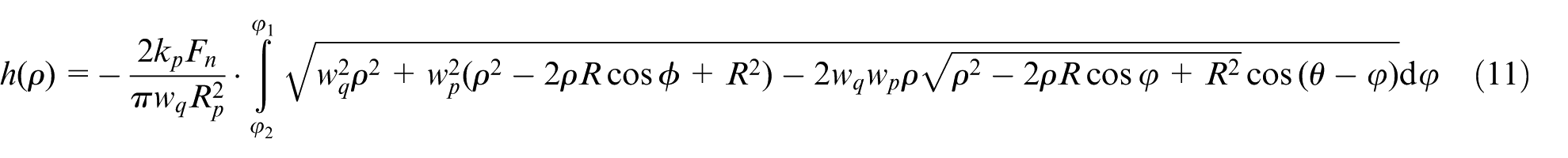
Assuming that the normal force Fn and angular feed velocity wq maintain constant when the sub-aperture tool passes across H. Substitution of equations (4) and (10) into equation (3) yields
The contact circle can be expressed in the frame XOY by
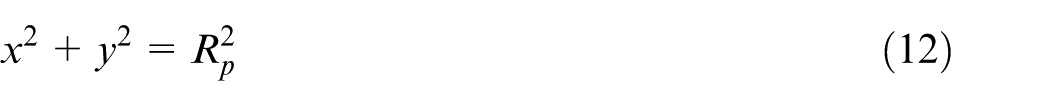
In order to convert the expression of equation (12) into the frame XOY, substitution of equation (9) into equation (12) yields
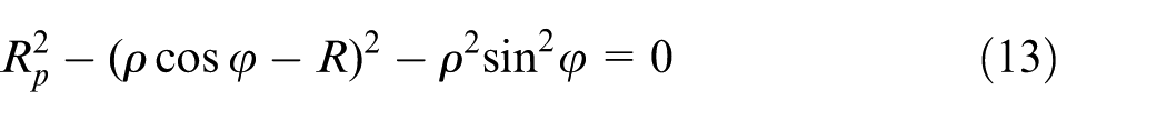
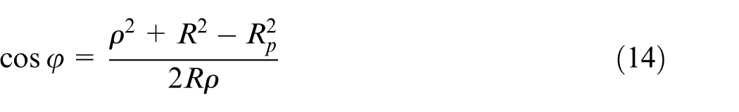
And from equation (13), cosφ can be solved as
As indicated in Figure 2, for ρmin < ρ <ρmax, φ1 is within [0, π/2] and φ2 is within [-π/2, 0], thus
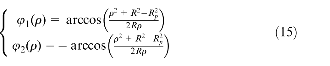
The values of φ1 and φ2 are the functions of ρ. Substitution of equation (15) into equation (11) yields
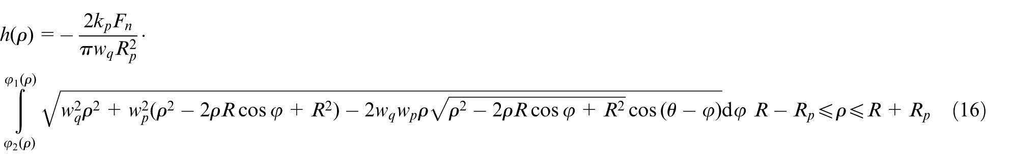
The equation (16) is a function of ρ and the material removal profile orthogonal to the tool path can be obtained from solving the equation (16) by varying ρ from R-Rp to R + Rp.
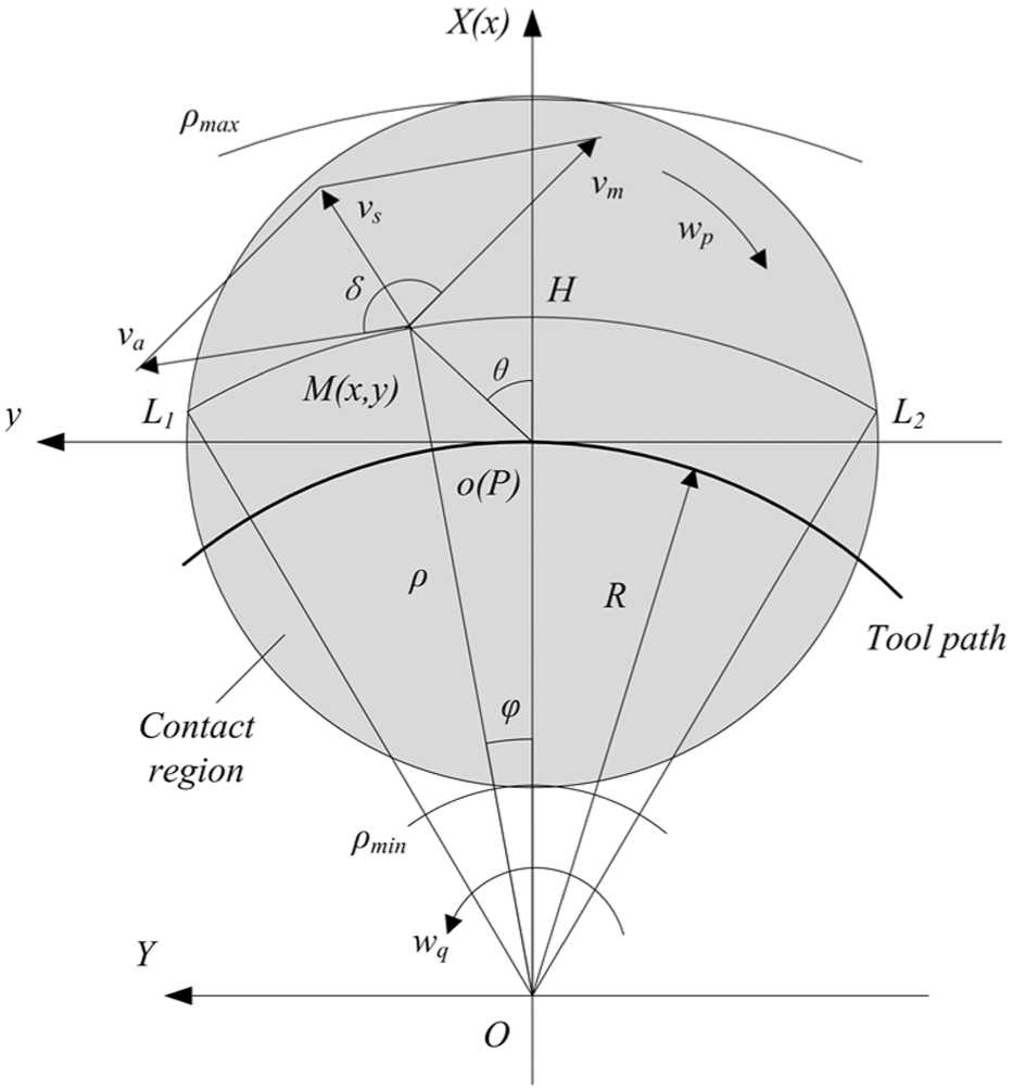
Schematic of the sub-aperture pad polishing along the circular path.
Experimental verification and discussion
Experimental verification
As shown in Figure 3, a new polishing system of biaxial rotary motion is developed. The polishing experiments were conducted on the polishing system of biaxial rotary motion. Then the experimental removal profile is compared with the theoretical ones calculated by equation (16). The polishing machine tool consists of three translational axes (X axis, Y axis and Z axis) and two rotational axes (B axis and C axis). The polishing spindle is mounted on the B axis with a speed adjustable from 1000 to 20,000 r/min. By rotating B axis, the suitable polishing attitude can be adjusted. A more detailed schematic of the polishing spindle is shown in Figure 3(b). As indicated by Zhao et al., 19 the normal force plays an important role on the material removal during the polishing. For the deterministic polishing process, the normal force should be under control during the polishing process. A piezoelectric force sensor is mounted on the polishing spindle to measure the normal force, and the signal from the sensor is used as a feedback to control the polishing force varying from 1 to 10 N. The workpiece is fixed on the rotational table of C axis. The angular displacement and velocity of C axis is also under control.
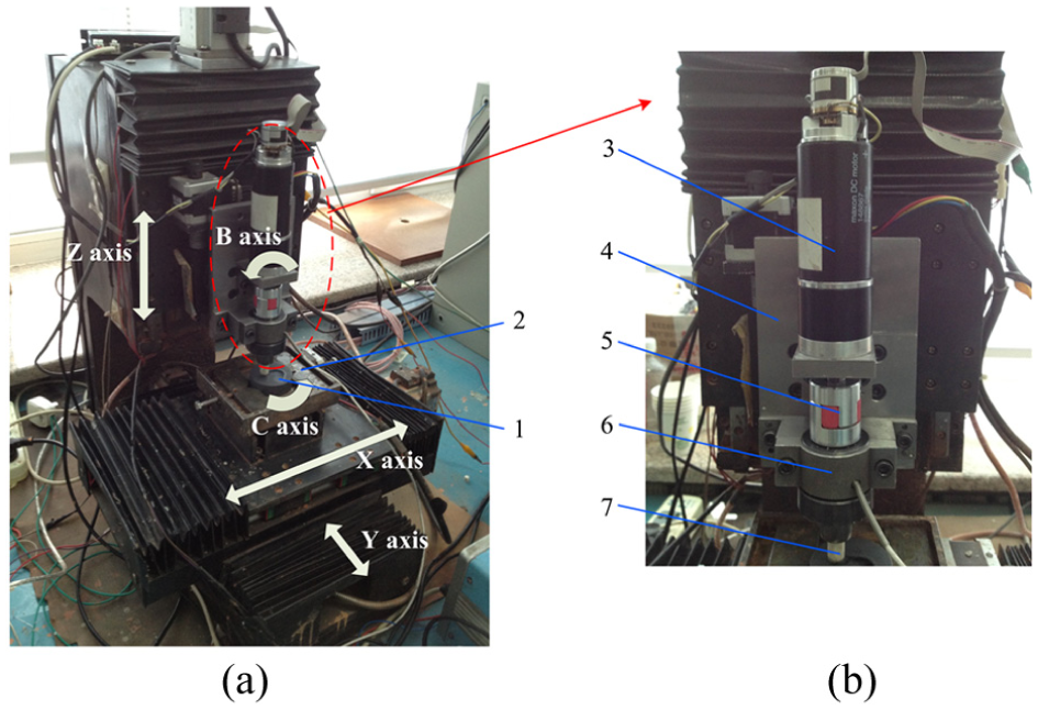
Structure of the polishing system (a) polishing system of biaxial rotary motion and (b) polishing spindle with force control.
According to the structure of the polishing system, the machine tool is especially suitable to polish the symmetrical aspheric part surfaces. The motion pattern of the polishing system is shown in Figure 4. The biaxial rotary motions, which correspond to the rotations of the polishing spindle and workpiece, are used during the polishing. The angular velocities of the spindle and the workpiece are wp and wq. The concentric circular path is a good choice for the axis-symmetrical part surfaces because every point on the same circle path has the same geometric properties, making the polishing process easy to control. As shown in Figure 4, when the polishing tool dwells on a certain point on the meridian under a constant polishing force Fn, the workpiece is rotating around the center. After that, the polishing pad moves to the next point along the meridian. When the polishing tool moves to the center of the workpiece, the whole surfaces is polished.
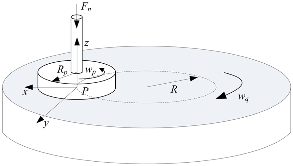
Schematic diagram of the polishing motion pattern.
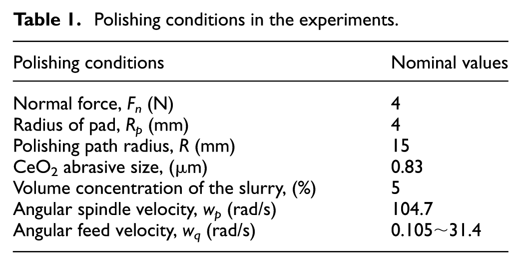
In the experiments, flat specimens of the glass ceramics were used for the removal experiments. The nominal values of the experimental parameters are shown in Table 1. The sub-aperture polishing pad (JA-CP from Trojan) with the radius of 4 mm was used in the experiments. In the polishing experiments, the polishing pad was placed on the position with the distance of 15 mm to the rotating center of the workpiece. The value of the normal force was fixed at 4 N, and the angular spindle velocity was set to 104.7 rad/s. The angular feed velocity varied from 0.105 to 31.4 rad/s in the experiments. The concentration of the polishing slurry by volume was 0.5%. Commonly used particles of CeO2 were used as free abrasives, and the average radius of the abrasive particle was 0.83 μm. In order to obtain a deep material removal profile, the workpiece was polished by moving the sub-aperture pad along the tool path 100 times. The material removal profiles were measured by the Form Talysurf PGI 810 (Taylor-Hobson Ltd., UK) along a line orthogonal to the tool path. The radius of the measuring stylus tip was a 0.3 mm. The measurements were conducted under the waviness mode to suppress the high-frequency noise of the profiles and the measured data are illustrated from Figures 5–10.
Polishing conditions in the experiments.
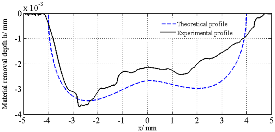
Material removal profiles for ωp = 104.7 rad/s and ωq = 0.105 rad/s.
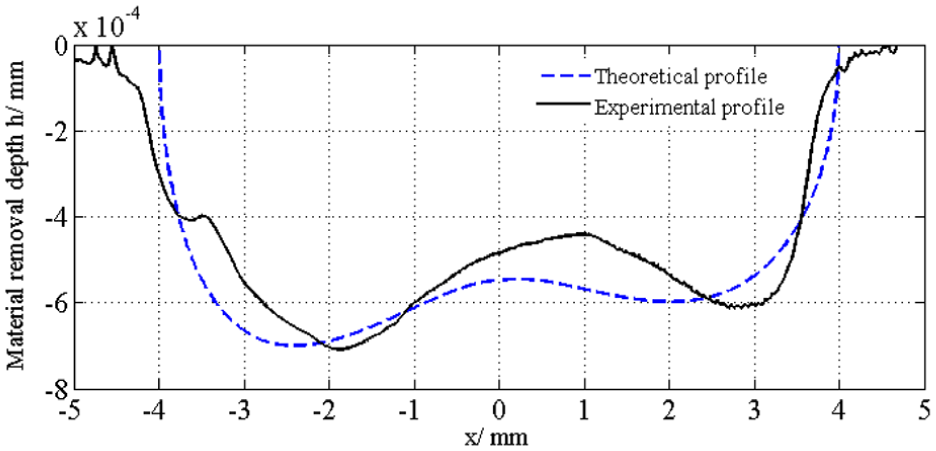
Material removal profiles for ωp = 104.7 rad/s and ωq = 0.512 rad/s.
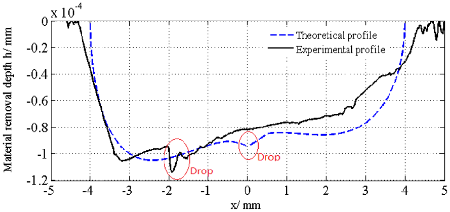
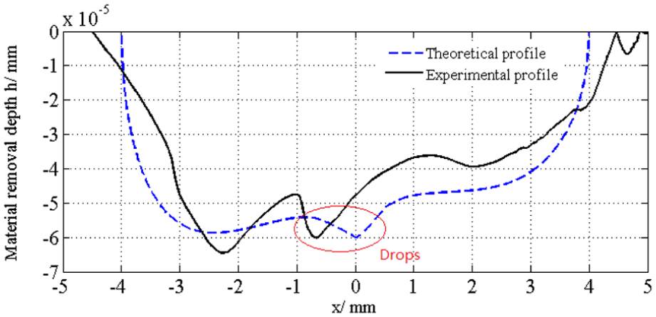
Material removal profiles for ωp = 104.7 rad/s and ωq = 3.14 rad/s.
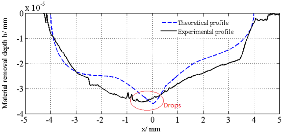
Material removal profiles for ωp = 104.7 rad/s and ωq = 5.23 rad/s.
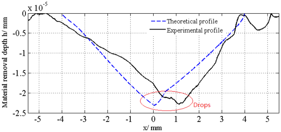
Material removal profiles for ωp = 104.7 rad/s and ωq = 10.47 rad/s.
Material removal profiles for ωp = 104.7 rad/s and ωq = 31.4 rad/s.
The theoretical profiles are calculated on the basis of equation (16). The Preston coefficient kp is chosen from trial and error by fitting the theoretical removal depths to the experimental ones. The value of kp is 3.13×10⁻⁷ in the experiments. In the Figures 5–10, the dotted lines indicate the theoretical removal profiles calculated by equation (16) and the solid lines are the experimental ones. According to these figures, the theoretical profiles are consistent with the experimental ones, which validate the accuracy of the proposed model in predicting the material removal during the polishing process.
Discussion
For the angular spindle velocity, wp =104.7 rad/s and the angular feed velocity wq = 0.105 rad/s, the removal profile is shown in Figure 5. In this case, the spindle velocity is much bigger than the feed velocity, thus the relative sliding velocity in the contact region is mainly determined by the spindle velocity. According to Figure 5, the removal profile has two summits on the both sides and a valley in the middle. It is attributed to the sliding velocity due to the spindle rotation vm increasing from the center to the sides. 5 Meanwhile, the summit near the curvature center O of the tool path has deeper material removal than the one on the other side of the profile. The deviation of the removal profile to the curvature center is owing to the contact region near the curvature center of the tool path having long dwelling time when polishing along a curved path. 23 Similar shape of material removal profile is found in Figure 6 as wp increases to 0.512 rad/s. Although the removal profile in Figure 6 shows similarity with that in Figure 5, the removal depth is decreasing. It is because that large angular feed velocity corresponds to less dwell time over the entire contact region, and relative small amount of material are removed from the part surface.
For wp increases to 3.14 and 5.23 rad/s, the material removal profiles are shown in Figures 7 and 8, respectively. It can be seen from Figures 7 and 8 that both the theoretical and experimental results show that there are small drops at the center of the profiles. Moreover, compared to Figures 8 and 7, the size of the drop is increasing with wq. It can be expected that as wq increases to a certain extent, the material removal profile would have a central peak.
As shown in Figures 9 and 10, when wq further increases to 10.47 and 31.40 rad/s, the theoretical and experimental results both have peaks in the middle of the profiles. The drops in Figures 7 and 8 develop into the central peaks. In this case, the effect of the feed velocity on the material removal profile is large. The increase of the feed velocity enlarges the sliding velocity at the center. Thus, when the feed velocity is raised to a certain value, the removal profile would have a central peak. In order to control the amount of material removed by the polishing process, the ideal material removal profile should be symmetrical and with a central peak. It is obvious that the profiles in Figures 5–8 are asymmetrical and biased toward the curvature center. These profiles are not suitable for the polishing process to correct the surface form error. The profiles in Figures 9 and 10 have a better characteristic of symmetry and are with peaks in the middle, which makes them suitable for the polishing process compared with these in Figures 5–8.
In order to investigate the evolution of the shape of the removal profile, the theoretical removal profiles are normalized by

where Max(|h(ρ)|) is the maximum depth of the theoretical polished profile. Figure 11 shows the normalized material removal profiles of the different polishing parameters. As indicated in Figure 11(a), for the polishing path radius R = 10 mm, the shapes of the removal profiles are varying with the different values of wp/wq. When wp/wq = 2.5, the material removal profile has a central peak, which is almost acceptable for the polishing process. For the polishing path radius R = 30 mm, the suitable removal profile is obtained when wp/wq = 10. Comparing the Figure 11(a) and (b), it is not difficult to find that the evolution of the material removal profile is not only affected by the ratio of the angular spindle velocity and the angular feed velocity, but also the polishing path radius. As indicated in equation (7), the feed velocity is the product of angular feed velocity and the radius of polishing path. When the angular feed velocity is kept constant, the radius of polishing path would affect the distribution of the feed velocity in the contact region, which has further effect on the shape of the removal profile.
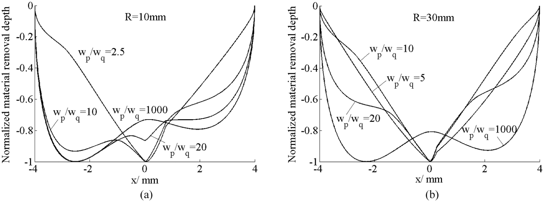
Normalized material removal profiles. (a) Normalized material removal profiles for R = 10 mm and (b) normalized material removal profiles for R = 30 mm.
Optimization of the removal profile
In polishing, the ideal material removal profile should have the largest material removal at the center. In order to make the removal profile more suitable for the corrective polishing process, the polishing parameters should be optimized to obtain a better profile. T1 is defined as the area between the removal profile and lateral axis, which gives

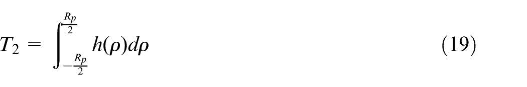
where Rp is radius of the contact region. T2 is defined as the area between the removal profile and lateral axis within the distance of half of the contact radius, which gives
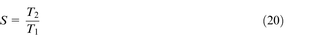
The tending gene S, which is defined as the ratio of T2 and T1, is used to evaluate degree of the aggregation of the removal profile to the center. The expression of tending gene S is given by 24
Assuming that when the tending gene S reaches the maximum value, the corresponding parameters would result in an optimal removal profile. As shown in Figure 12, for R = 30 mm and wp =104.7 rad/s, the tending gene S reaches the maximum when wq = 4 rad/s. Meanwhile, for R = 90 mm and wp = 104.7 rad/s, the tending gene S has a maximal value when wq = 12 rad/s. According to the optimized parameters in Figure 12, the optimal material removal profiles for R = 30 mm and R = 90 mm is shown in Figure 13. The optimized removal profiles in Figure 13 is almost symmetrical and with a central peak.
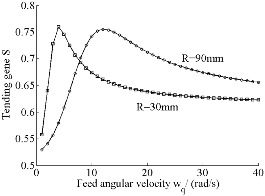
Relationships between tending gene S and feed angular velocity wq for various polishing path radius R.
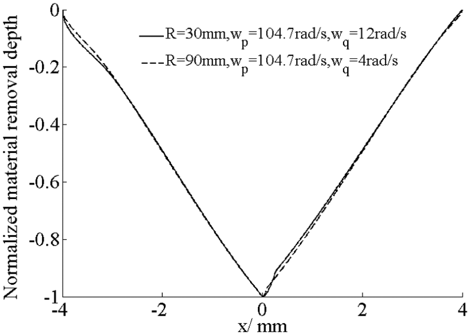
Normalized optimal material removal profiles.
As discussed in the last section, the shape of the removal profile is affected by the spindle angular velocity, feed angular velocity and polishing path radius. Thus, the velocity ratio V is defined as
The relationships of tending gene S and velocity ratio V for various polishing path radii are indicated in Figure 14. For the polishing path radius R increases from 10 to 60 mm, the value of velocity ratio V when S reaches the maximum remains relatively constant. Therefore, the velocity ratio V should be kept between 3 and 4, which makes the material removal in the actual polishing process easy to control.
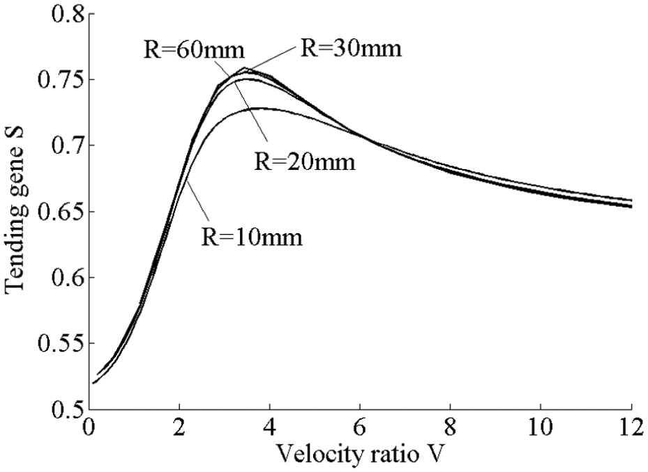
Relationships between tending gene S and velocity ratio V for various polishing path radius R.
Conclusion
The material removal profile in the contact region is used to characterize the material removal during the polishing process and a new method to calculate the material removal profile is presented in this article. According to the model, the shape of the profile is determined by the angular feed velocity, angular spindle velocity and polishing path radius.
The polishing experiments were conducted on the polishing system. The experimental profile is in good agreement with the theoretical ones, which validate the proposed model in this article. According to the experimental and theoretical results, when wp is much bigger than wq, the material removal profile is saddle-shaped with two submits on the sides and is biased toward the curvature center of the polishing path. With the increase of wq, there is a drop in the middle of the removal profile.
The tending gene of the profile is defined in this paper and the principle of tending gene maximization is used to optimize the removal profile. When wq increases to a certain value, the material removal profile would has a central peak; and when (R*wq)/wp = 3∼4, the removal profile shows good symmetry, which is most suitable for the demand of corrective polishing process. This article has laid a theoretical foundation for the further experimental study on the polishing of optical aspheric part surfaces.
Footnotes
Declaration of conflicting interests
The author(s) declared no potential conflicts of interest with respect to the research, authorship, and/or publication of this article.
Funding
The author(s) disclosed receipt of the following financial support for the research, authorship, and/or publication of this article: The authors would like to express their sincere thanks for the financial support from Basic Research Program of Jiangsu province (Natural Science Foundation) (Grant No. BK20150330), Chinese National Natural Science Fundation (Grant Nos 51505312 and 51605438) and Chinese Postdoctoral Science Foundation (Grant No. 2015M571800).