
Abstract
The deterministic polishing process is usually used as the final step to produce part surfaces of high surface finish and form accuracy. This article presents the models of the local and the global polished profiles for the deterministic polishing process when a surface is polished by a spherical polisher. The local polished profile is modeled by integrating the index of material removal, which is defined as the polished depth at unit length of the polishing path, at each tool–surface contact region. According to the model, the local polished profile is determined by the process parameters, the tool attitude, the measuring angle and the geometrical/mechanical properties of workpiece and tool. The linear algebraic expression of the global polished profile is derived by convoluting the local polished depth at each dwell point of the polishing process. The polishing experiments are conducted to verify the proposed model in the different polishing conditions. Moreover, simulation results are given to illustrate the application of the proposed model in optimizing the feed rate to minimize the surface form error in the deterministic polishing process.
Introduction
Recently, the needs for free-form part surfaces have been widely recognized in optoelectronic and communication industries. The components with free-form surfaces not only occupy superior optical properties but also reduce the volume and weight for the optical products. The fabrication of high-quality and precision part surface is becoming more and more stringent in manufacturing. The manufacturing process for high-precision part surfaces typically involves a series of steps including generating, fine grinding, polishing and corrective polishing by sub-aperture tool. 1 As the final step for the fabrication, the polishing process is essential to the quality and duration of the part surfaces. A polishing process is considered to be deterministic if the material removal behavior during the polishing process is predictable whenever the processing parameters are set to fixed values. 2 Different from the traditional polishing process which merely aimed at reducing the roughness of the part surface, the deterministic polishing is regarded as an error compensation process to eliminate the form error left by the precision grinding or diamond turning process.2,3 In recent years, much research has been performed on the deterministic polishing process, focusing on the design of polishing system,4–6 polishing mechanism,7–9 prediction of roughness, 10 tool path planning11,12 and so on. Apart from the studies discussed above, efforts are also devoted to the material removal during the polishing process. It is essential to model and analyze the material removal of polishing in a quantitative manner so as to enhance the reproducibility and controllability of the deterministic polishing process.
The orbital motion is commonly used to polish large optics, and the material removal function of the orbital motion was studied and optimized by Jones.13,14 The polishing of small surface components usually employs a rotational spindle at specific angular velocity with a small spherical or cylinder polisher. To model the material removal during the polishing, one should get the knowledge about the wear rate and tool–surface contact during the polishing. Preston’s equation is widely used to model the wear rate during the polishing, which indicates that the material removal is proportional to the contact pressure, sliding velocity and dwell time. 15 Based on Preston’s equation, Kim and Kim 16 presented a model of material removal function, which is also called time influence function, by assuming the distribution of pressure in the contact region to be Gaussian. Similar model was also developed by Cheung et al. 17 Due to the geometric properties of part surface, the size of tool–surface contact region is different from point to point. According to the study by Song et al., 18 the pressure distribution at the contact agrees with the Hertzian contact theory, and the rotational speed, polisher decrement and curvature radius of surface all have effects on the material removal. Yang and Lee 19 modeled the local material removal rate by assuming the contact between the polisher and surface to be Hertzian. According to their study, the material removal rate during the polishing is not invariant due to the curvature effect. However, the above listed models of material removal can only be used to predict the removal depth and profile when the tool polishes on a single point. In order to control the amount of material removed precisely by using these models, the tool should be commanded to dwell at each dwell point on the tool path according to the computed dwell time and then move to the next point. The dwell-and-go mode makes the machine tool start and stop frequently, which is time-consuming and hits the acceleration and deceleration limits of the machine tool.
In an earlier research by Zhang et al., 20 the polished profile and depth were directly linked to the feed rate along the tool path by assuming that the wear rate during the polishing follows Archard law. According to their study, the polished profile orthogonal to the tool path is parabolic, and the polished depth depends on the tool–surface geometry and the process parameters (normal force, feed rate, spindle velocity, etc.). If the part surface is axisymmetric and the concentric tool path is used, the measuring direction of form error is naturally along the meridian of part surface, thus the model of polished profile orthogonal to the tool path can be used to optimize the feed rate.21,22 However, a more common condition that the part surface is nonaxisymmetric and the tool path is not concentric makes the measuring direction not orthogonal to the tool path, as shown in Figure 1. Therefore, as the polisher moves along the tool path on a nonaxisymmetric free-form surface, a model related to the polished profile in the measuring direction is needed. Such a model is useful for the process planning of the deterministic polishing.
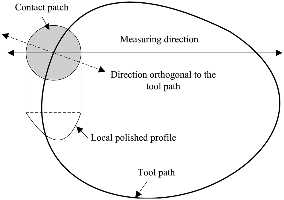
Schematic diagram of polishing along a tool path.
In this article, the polished profile is defined as the depth of material removal along the measuring direction, as shown in Figure 1. In section “Local polished profile,” the local polished profile is derived by integrating the removal index along the tool path at the tool–surface contact patch. The expression of the global polished profile along the measuring direction is developed in section “Global polished profile,” by superimposing the local polished profile at each dwell point. The validity of the presented model for polished profile is verified by experiments in section “Experimental verification and discussion.” The application of the proposed model in the process planning is illustrated in section “Application.” Findings are summarized in section “Conclusion.”
Local polished profile
As shown in Figure 2, as the tool moves across the point P, the feed rate of the tool along the tool path is va
and the angular spindle velocity is ω. Establish a local coordinate system {
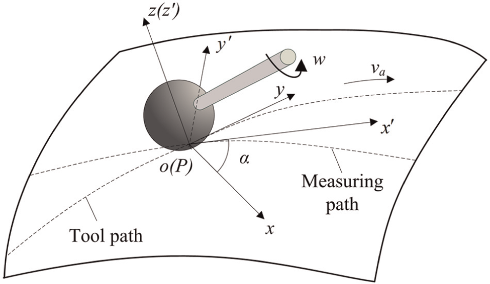
Definition of the local coordinate systems.
During the polishing, a contact patch is formed between the spherical tool and part surface, within which the material removal takes place. The Hertzian contact theory is widely used to model the distribution of pressure in the contact patch.18–20 According to Hertzian contact theory, in the coordinate frame x′oy′, the distribution of the contact pressure is given by23,24
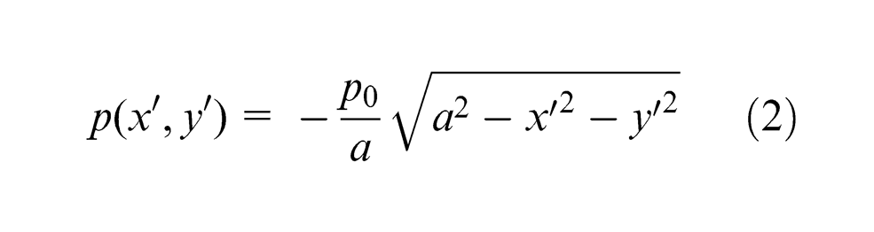
over the contact circle
where a is the radius of the contact patch which is determined by the polishing normal force and the material properties of the workpiece and the polisher, as indicated in Appendix 2. In equation (2), p 0 is the pressure at the center of the contact circle which is given by
where Fn is the normal polishing force.
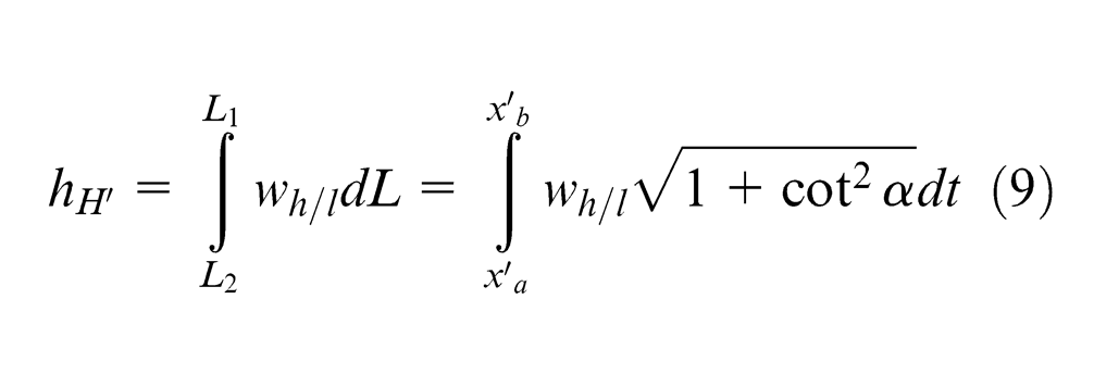
Figure 3 shows the contact circle between the polisher and part surface. Let H be an arbitrary point on the x-axis. When the tool feeds along the polishing path, the contact patch is also moving. The material removal at H is accumulated as the contact patch feeding across H, thus L 1 L 2 in Figure 3 can be regarded as the polishing belt for the material removal at H. The index of material removal at H

is defined as the polished depth at unit length of polishing path. Thus, the polished depth at H can be calculated by integrating wh/l along the tool path from L 2 to L 1, which gives
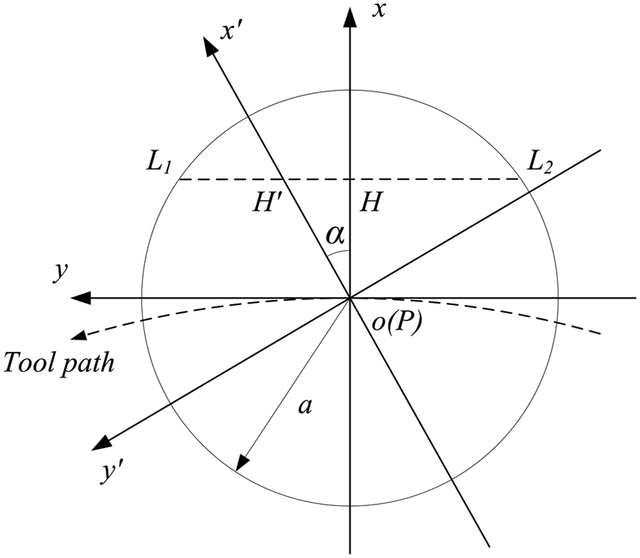
Geometric entities in the contact patch.
According to Archard wear law, the index of material removal is derived by Zhang et al. 20 as
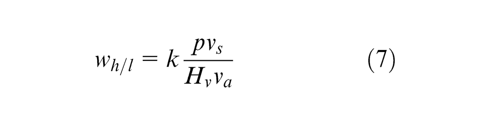
where k is the wear coefficient, p is the contact pressure, vs and va correspond to the relative sliding velocity and feed velocity, respectively, and Hv is the hardness of the part surface.
Let
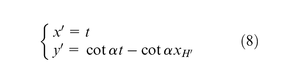
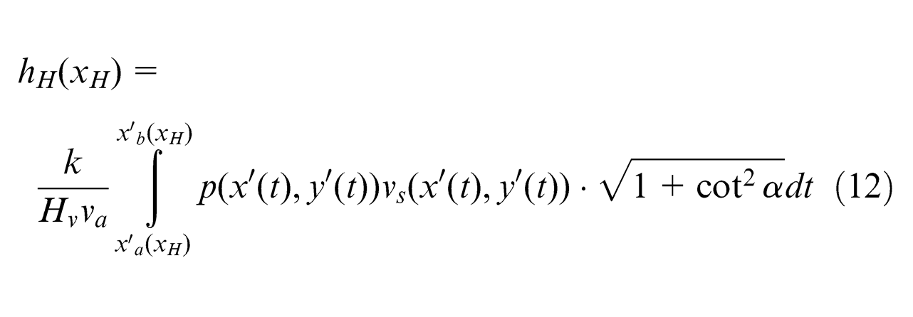
By integrating wh/l along L 1 L 2 in the coordinate frame x′oy′, the polished depth at H′ can be obtained, which gives
where
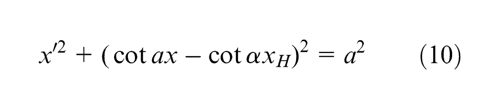
from which
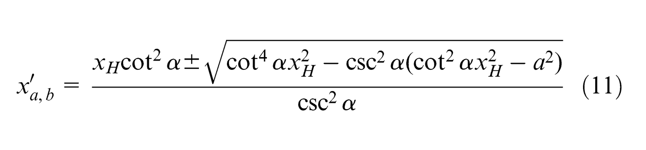
Substituting equations (7), (8) and (11) into equation (9), the polished depth at H′ can be expressed as
in which va
is assumed to be constant since the contact patch is small. As the value of
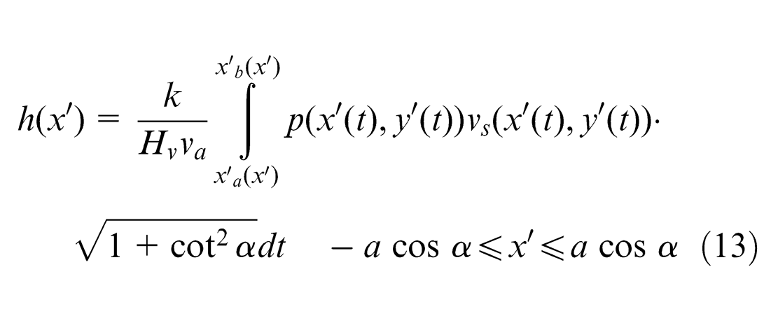
As indicated by equation (13), the distribution of the pressure and the relative sliding velocity in the contact patch is essential to the computation of the local polished profile. The velocity distribution in the polishing contact patch can be predigested in Figure 4. In Figure 4, the local coordinate system {
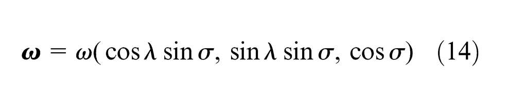
where ω = |
where
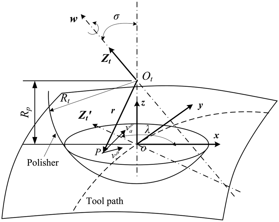
Schematic diagram of polishing attitude and relative sliding velocity in the contact patch.
The sliding velocity
On the other hand, the feed velocity at P can be expressed as a vector by
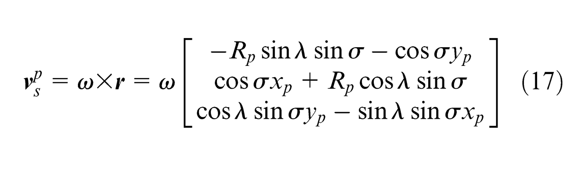
For the spherical tool polishing on a surface, only the tangential components of the velocity have effect on the material removal in the contact patch. Thus, the relative sliding velocity at point P(xp, yp, zp ) is
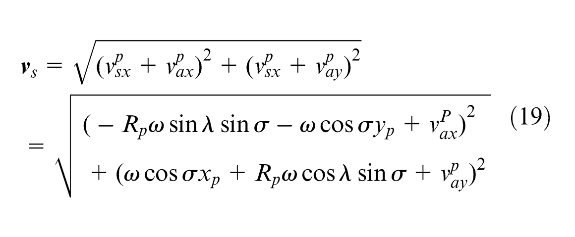
In the actual polishing process, the feed rate
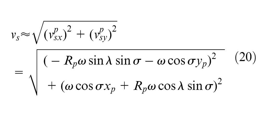
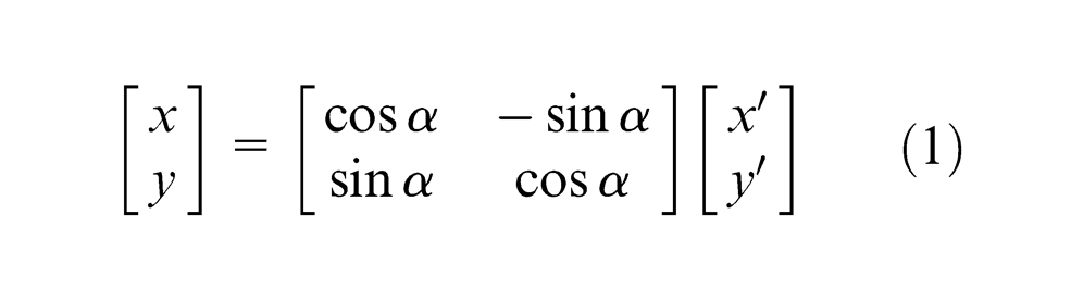
Equation (20) is the expression of the relative sliding velocity in the coordinate frame xoy. By substituting equation (1) into equation (20), the distribution of the relative sliding velocity in the coordinate frame x′oy′ can be obtained, which gives
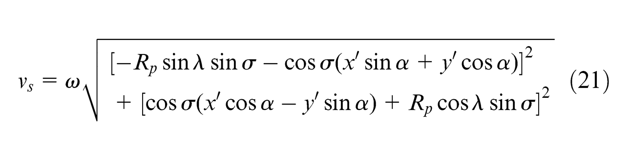
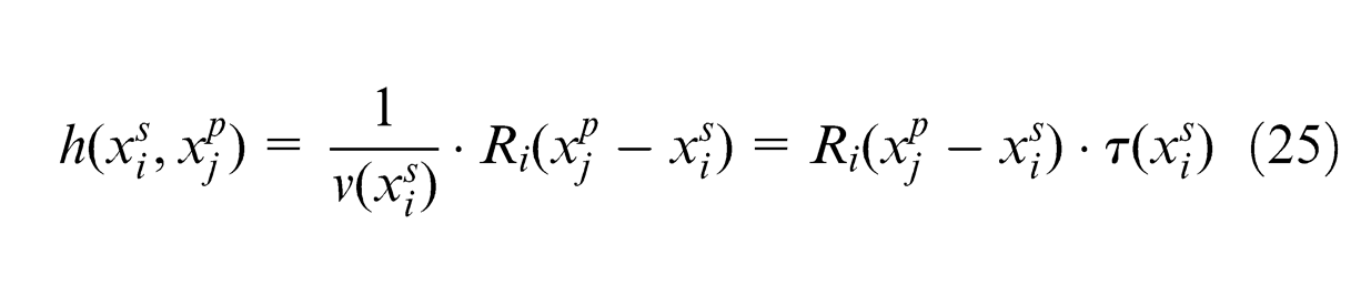
Further substituting equations (2) and (21) into equation (13), the local polished profile in x′-direction can be expressed by
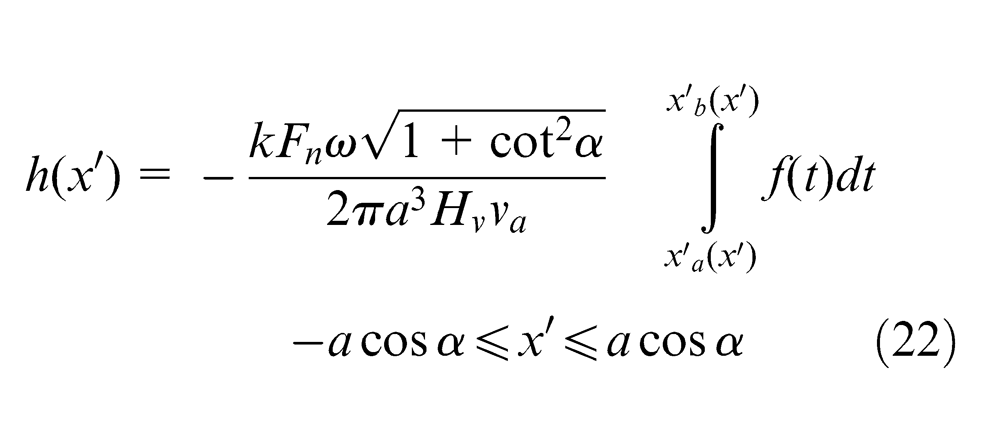
where
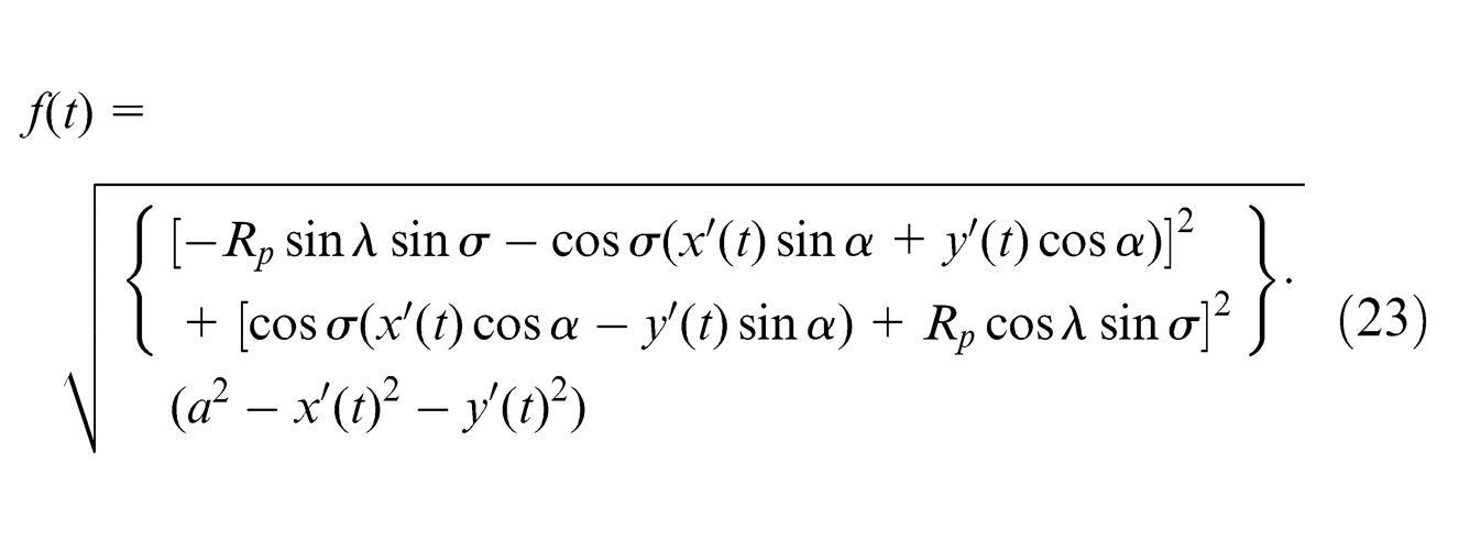
where x′(t) and y′(t) are given by equation (8), and
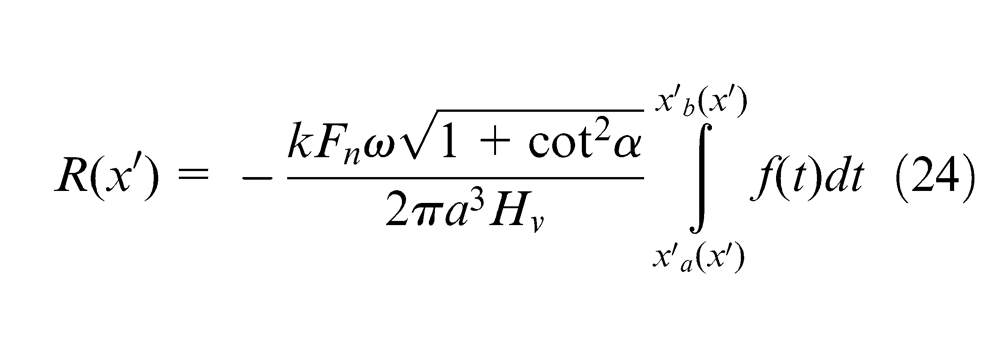
which represents the polished depth at the unit feed rate.
Global polished profile
The interaction of the tool path and measuring path is illustrated in Figure 5. During a polishing cycle, the part surface is entirely covered by the tool paths, and the spherical polisher moves along the tool paths. And the form accuracy of the part surface is measured by a certain instrument along the measuring path. The intersections of the tool paths and the measuring path are the tool dwell locations, which are defined as the dwell points
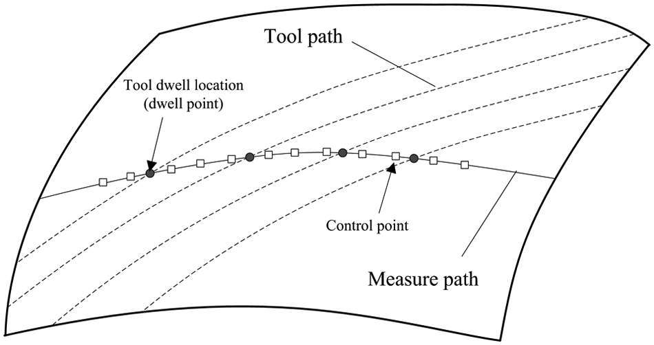
Dwell points and control points on the measuring path.
As shown in Figure 6, suppose that the current dwell point is
where
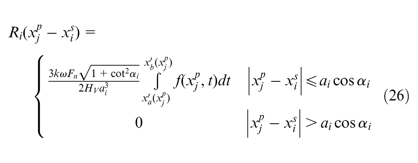
where αi
is the measuring angle and ai
is the contact radius at dwell point
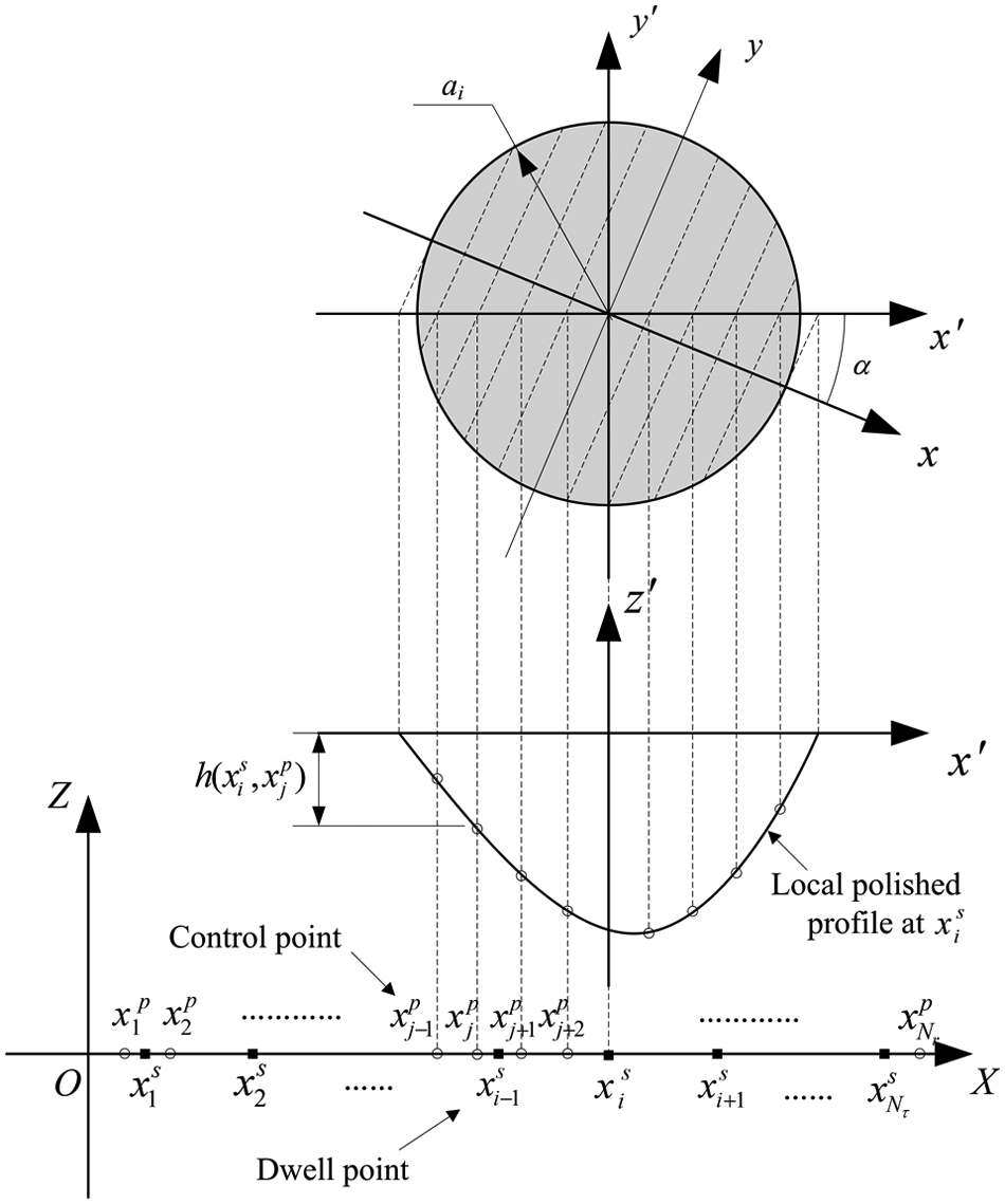
Schematic diagram of the global polished profile.
If the polisher has visited all the dwell points on the measuring path, the actual depth of material removal at
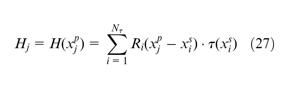
where Hj is the polished depth at jth control point. The total polished depth along the measure path can be expressed in a vector form by
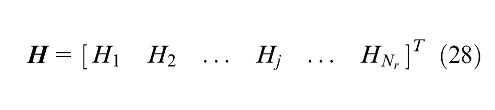
Finally, the global polished profile is described in the discrete form as
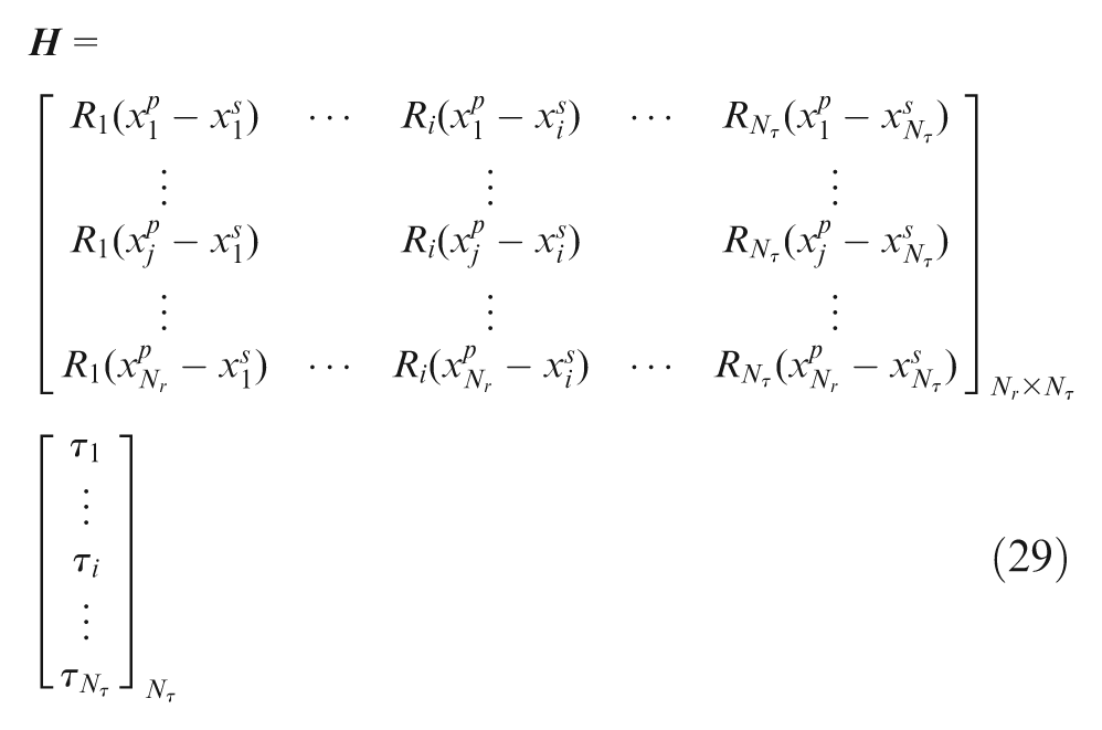
Equation (29) can be abbreviated as

where
For a given set of tool dwell locations, the influence matrix
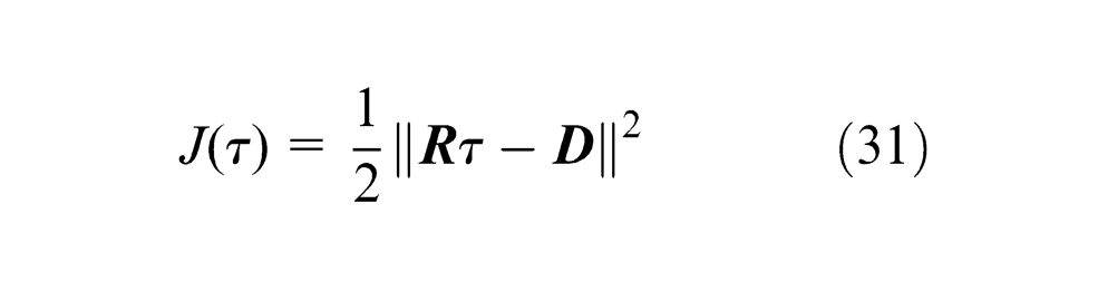
where ||·|| denotes the two-norm of a vector or matrix. The basic optimization problem of deterministic polishing planning can be formulated as

Since the values in
Experimental verification and discussion
The focus of this section is to validate the model of the polished profile as suggested in equation (22) and show how the shape of the polished profile varies with the measuring angle α. The polishing experiments are conducted on a five-axis polishing machine that is composed of three translational axes (X-axis, Y-axis and Z-axis) and two rotational axes (B-axis and C-axis), as shown in Figure 7(a). The piezoelectric force sensor is mounted on the end effector of the polishing spindle, which is used as a feedback sensor to control the polishing force. The polishing normal force Fn is set at 4 N in the experiments. The spherical polisher is made of polyurethane with the radius of 4 mm. The angular spindle velocity is set to 104.7 rad/s in the experiments. The flat specimens of glass ceramics are used for the polishing experiments. In order to get the mechanical properties of the glass ceramics, the nano-indentation experiment is made, in which the hardness Hv = 8300 MPa. The polishing slurry used in the experiments is a mixture of CeO2 powder and water. The volume concentration of the polishing slurry is 0.5% and average radius of the CeO2 particles is 0.83 µm. The polished profiles are measured by Form Talysurf PGI 1240 (Taylor Hobson Ltd, UK) along the measuring direction, which is illustrated in Figure 7(b). The radius of the measuring stylus is 0.3 mm. The measurements are conducted in the waviness mode to suppress the high-frequency noise of the profiles.
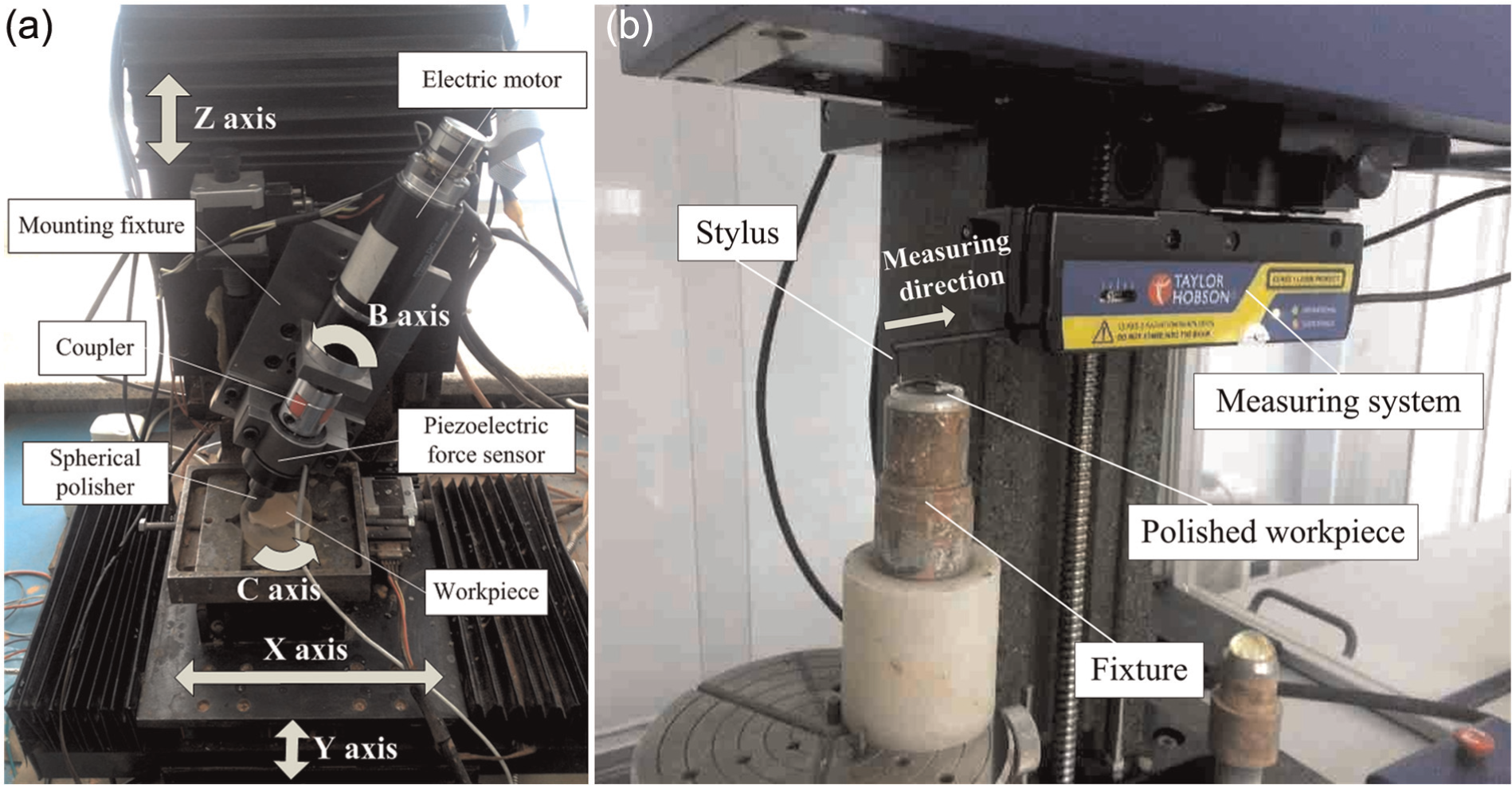
(a) Structure of the polishing machine tool and (b) measuring system and polished workpiece.
Figure 8 shows the planning of the polishing experiments. Experiments are performed by feeding the polisher along a straight path across the measuring path at va
= 0.1 mm/s. The attitude of the polishing tool is also important for the polishing experiments. By rotating the polishing spindle around the B-axis, the inclination angle σ is adjustable. As shown in Figure 8(a), in the first group of experiments, the inclination angle σ is fixed at 45°. The included angle of the tool feed direction and measurement direction varies from 90° to 30°, which corresponds to the angle α varying from 0° to 60°, respectively. The setting of the second group of experiments is illustrated in Figure 8(b). The inclination angle σ = 15°, and the measuring angle α varies from 10° to 50°. However, the declination angle λ is not constant in these experiments, which varies with different tool feed directions. As indicated in Figure 8, the declination angle λ has the same value as α since the
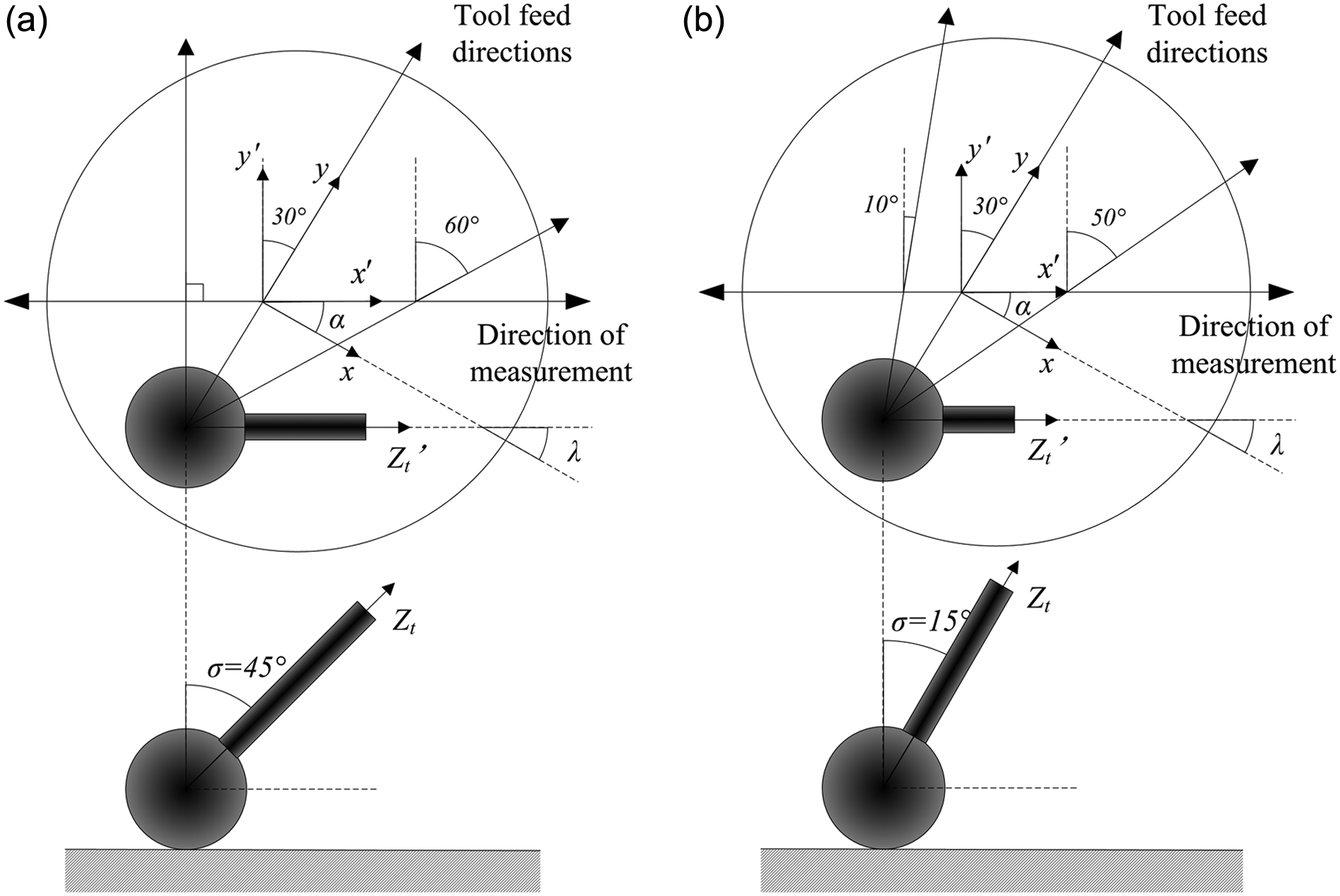
Planning of the polishing experiments: (a) σ = 45° and α varies from 0° to 60°; (b) σ = 15° and α varies from 10° to 50°.
The measured data are shown in Figures 9 and 10. In these figures, the dotted lines are the experimental results and the solid lines are the simulation results calculated by equation (22). The wear coefficient k in equation (7) is obtained from trial and error by fitting the theoretical polished depths to the experimental ones. The wear coefficient k is approximately 0.00624 in the experiments. The experimental and theoretical polished profiles show good agreement in Figures 9 and 10, which validates the proposed model in this article. In Figures 9 and 10, with the increase in α, both the simulations and the experimental results show that the width of the polished profile increases, while the depth decreases slightly. As indicated in equation (22), the width of the local polished profile equals to 2acos α, thus the increase in α may increase the width of the profile. On the other hand, the declination angle λ changing with α makes the polished depth decrease with the increase in α in these experiments. The contrast between Figures 9 and 10 shows that the polishing depth decreases with the decreasing inclination angle σ. It is attributed that increasing decreasing inclination angle would enlarge the relative sliding velocity in the contact path; hence, large amount of material can be removed. Moreover, in Figure 10, the polished profiles bias away from the center of the profiles. Comparing Figure 10 with Figure 9, it can be found that the polished profile tends to show larger deviation for a smaller inclination angle σ. Decreasing the inclination angle σ would increase the deviation of the relative sliding velocity in the contact area, which results in the large deviation of the local polished profile.
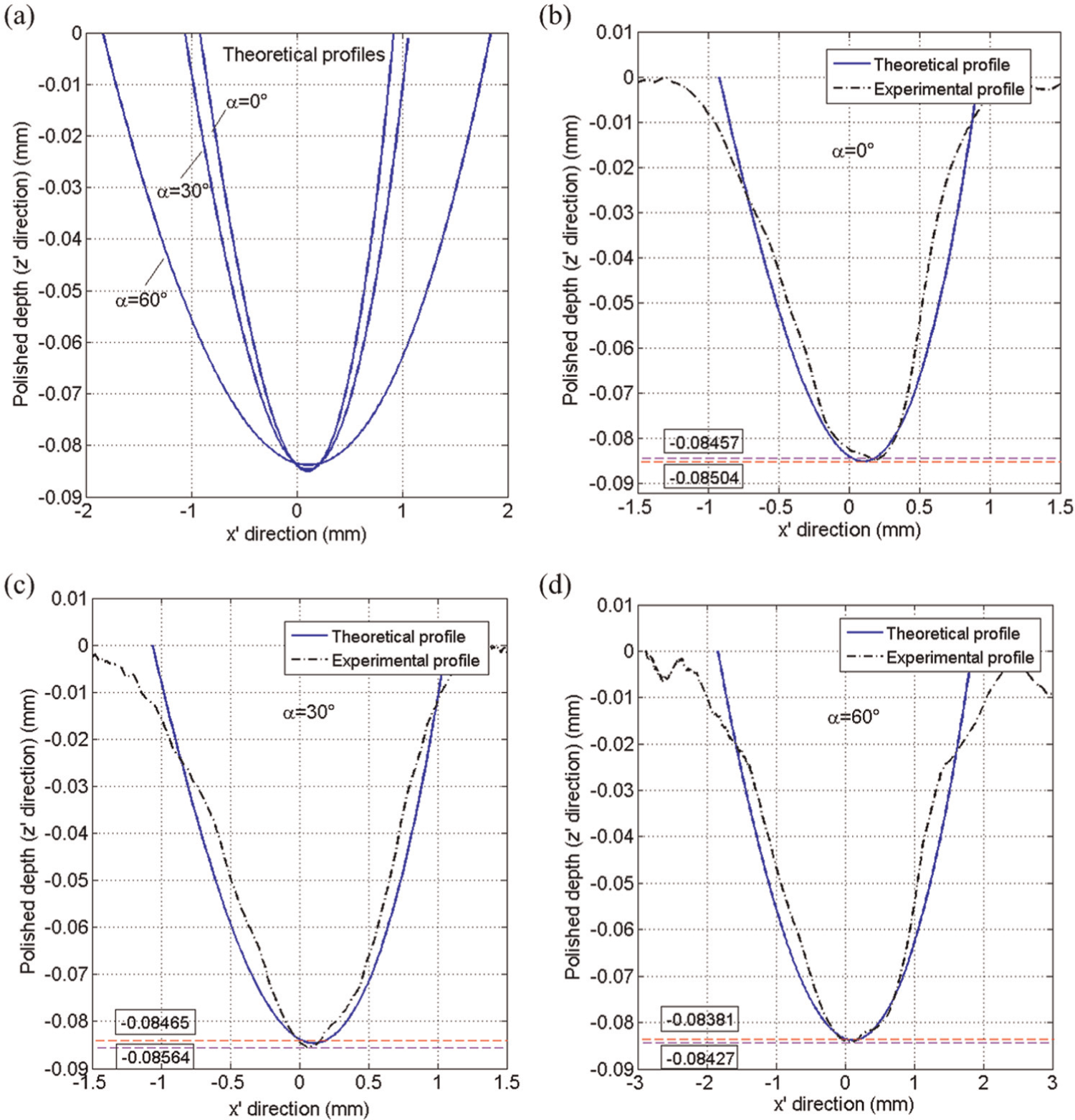
(a) Theoretical local polished profiles for the first group of experiments; experimental and theoretical profiles for (b) α = 0°, (c) α = 30° and (d) α = 60°.
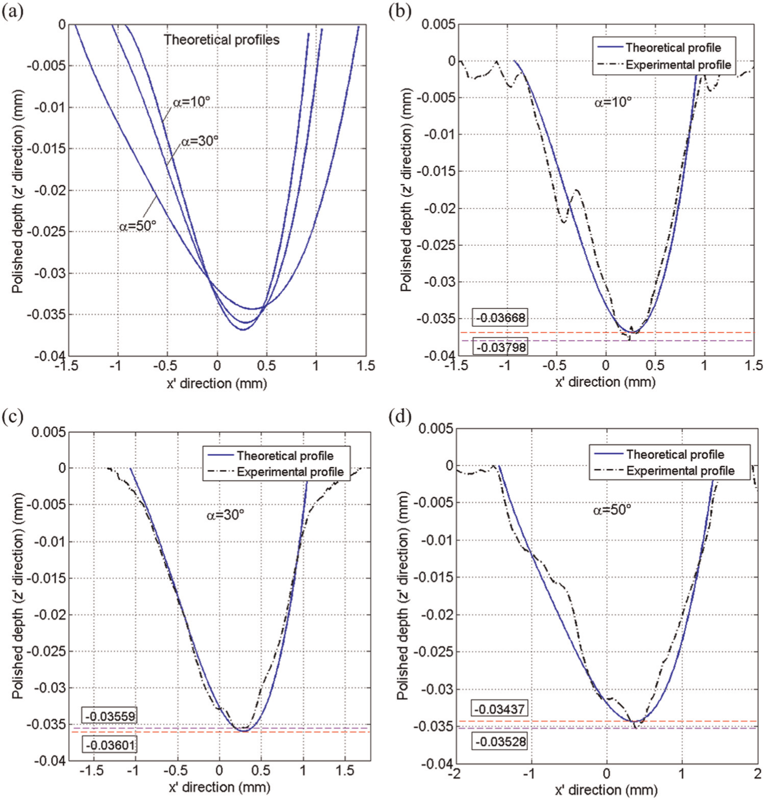
(a) Theoretical local polished profiles for the second group of experiments; experimental and theoretical profiles for (b) α = 10°, (c) α = 30° and (d) α = 50°.
Application
The model-based prediction of the local polished profile has been verified by the experiments in the last section. According to the proposed model, the local polished profile is essentially determined by process parameters, mechanical/geometric properties of part surface and polisher, polishing attitude and the measuring angle and so on. Equation (29) extends the local polished profile to the global polished profile, which is useful for the planning of the deterministic polishing process.
An ellipsoid part surface is selected to illustrate the computation of the polished profiles. A spherical polisher with radius of 4 mm is used. The mechanical properties of the polisher are the same as those in the last section. During the polishing process, the polishing attitude is set at σ = 30° and λ = 0°. The other settings of process parameters are the same as those in the last section.
The ellipsoid surface with radii of 20, 50 and 10 mm is given by
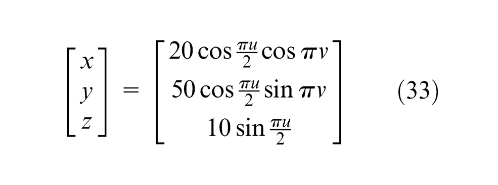
for 0 < u, v≤ 1, and all units are in millimeters. As shown in Figure 11, the tool paths are along constant values of u, which also can be obtained by intersecting the surface with the planes parallel to the XY plane. And the measuring paths are obtained by intersecting the surface with planes perpendicular to the XY plane. As the polisher feeds along the tool path across the measuring path, the measuring angle α is not constant. As shown in Figure 12(a), the measuring angle α varies from 90° to 0° along the measuring path. Moreover, the local radius of curvature of the surface is not constant along the measuring path, thus the radius of contact circle as the polisher feeds across the measuring path is different, as shown in Figure 12(b). Figure 13 shows the theoretical local polished profile along the measuring path of y = 10 mm as va = 1 mm/s. Due to the different measuring angles and contact radii, both the widths and depths of the local polished profiles at different locations along the measuring path are different.
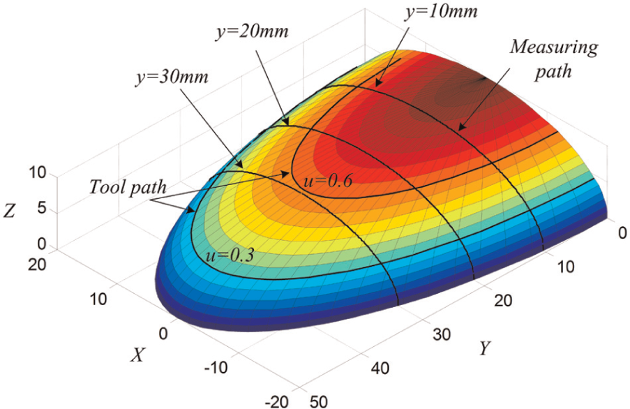
Tool paths and measuring paths on the ellipsoid surface.
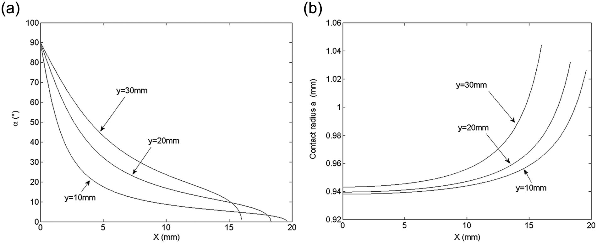
(a) Measuring angle and (b) contact radius varying along the measuring path.
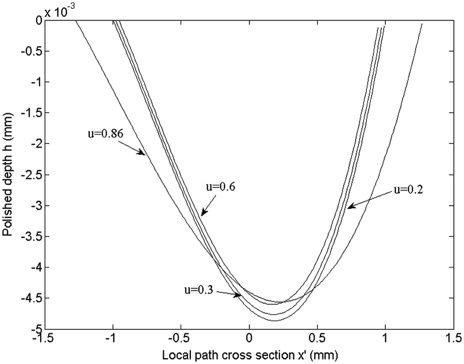
Local polished profile along the measuring path of y = 10 mm.
The deterministic polishing process is usually used to correct the surface form. According to the theory of Fourier transformation, the profile of the form error can be viewed as the combination of a uniform function and many sinusoidal functions with different wavelengths. 25 For the ellipsoid surface finishing example, assume that the designed depth function along the measuring path (y = 10 mm) may have a mathematical form of
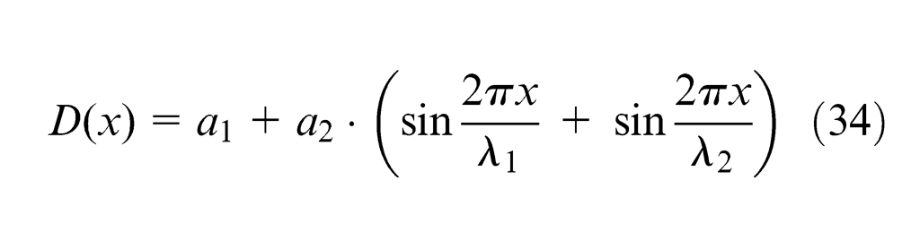
where λ
1 and λ
2 are the wavelengths of the sinusoidal error profile and a
1 and a
2 are two constants. Here, λ
1 = 6 mm, λ
2 = 12 mm, a
1 = 1.6 × 10⁻³ mm and a
2 = 1.6 × 10⁻⁴ mm. Thus, the designed removal depth distribution matrix
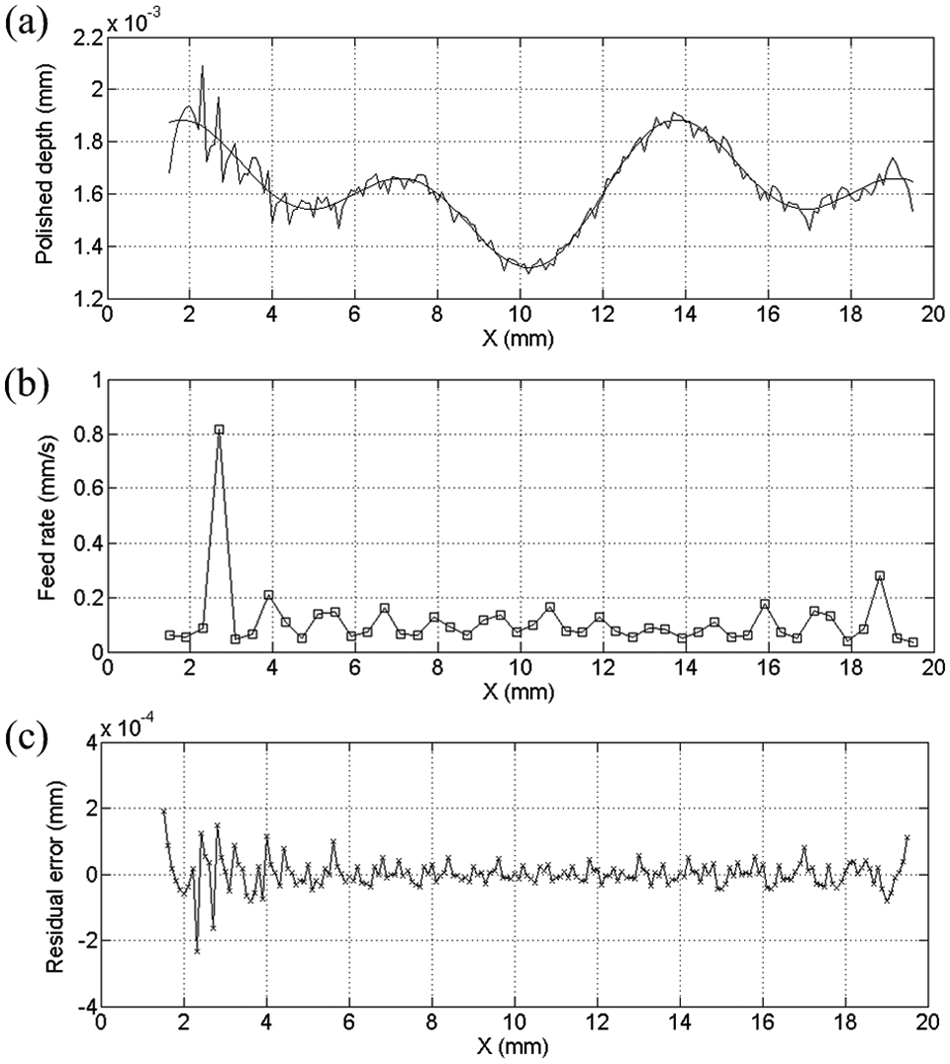
Polishing of an ellipsoid surface: (a) designed removal depth and actual polished depth, (b) dwell points and feed rates and (c) residual error.
In the computation, the interval of dwell point is 0.4 mm and the interval of control point is 0.1 mm. Since the contact radius and measuring direction have been calculated as shown in Figure 12, the local removal function R(x) in equation (26) can be calculated and the influential matrix of material removal
Conclusion
The models of the local and the global polished profiles for deterministic polishing process are presented in this article. The local polished profile is modeled by integrating the index of material removal along the tool path at each contact patch between spherical polisher and part surface. The algebraic expression of global polished profile is derived by convoluting the local polished depth at each dwell point of polishing process. According to the proposed model, the polished profile is determined by the process parameters (normal polishing force, angular spindle velocity and feed rate), mechanical properties of workpiece (workpiece hardness, Young’s modulus and Poisson’s ratio), geometric properties of part surface and polisher (local principle radius of the surface, radius of polisher, etc.), polishing attitude (inclination angle and declination angle) and the measuring angle.
In particular, this article focuses on the effects of the measuring angle and the polishing attitude upon the polished profile. The polishing experiments are conducted by varying the measuring angle. The experimental results agree well with the ones obtained by theoretical calculation, which confirms the validity of the proposed model. According to the experimental and theoretical results, the width of the local polished profile increases with the increasing measuring angle, and the depth is affected by the inclination angle and declination angle. Based on the derivation of the global polished profile, the application of the proposed model is illustrated to remove a specified amount of material from an ellipsoid surface along the measuring path. The feed rates along the tool paths at every dwell point are obtained by solving an optimization problem with nonnegative constraint. The NNLS method is used to determine the feed rate distribution of the tool. The result shows that the method is potentially useful for the process planning for the deterministic polishing process to correct the form error of the part surface.
Footnotes
Appendix 1
Appendix 2
Acknowledgements
The author Cheng Fan would like to thank the China Scholarship Council (CSC) for the financial support.
Declaration of conflicting interests
The authors declare that there is no conflict of interest.
Funding
This work is supported by Chinese National Program on Key Basic Research Project (973 Program) (grant no. 2011CB706702) and the Innovation Program of Jilin University for graduate students (grant no. 20121078).