
Abstract
In recent years, stringent governmental regulations along with falling carbon fiber prices have pushed high-volume composite manufacturing somewhere at the top of the “to do” list for the majority of carmakers. However, a careful survey of the literature reveals that little is available on the topic of high-throughput severing of the carbon fibers, one of the principal constituents of carbon fiber reinforced polymers. To address this relative paucity of valid scientific information, the major goal of this study was to develop a robust and accurate experimental apparatus capable of establishing correlations between the amount of cutting force developed at the blade/fiber tow/deformable backing interface and various process parameters such as fiber material, tow and backing characteristics, blade geometry/material, and so on. The characteristic cutting force–position curves obtained by means of the developed device suggest that (1) the cutting forces require to cut glass fibers are typically larger (up to 27% observed in this study), (2) softer backings tend to have a positive effect on the fiber severing process both in terms of peak cutting force and total work to cut, and (3) dull blades require either larger severing forces (60 µm blade edge radius was associated with a 21% increase in cutting force) or are simply unable to produce severing of the fibers (80 µm blade edge radius). Future extensions of this work will focus on the determination of systematic correlations between the parameters of fiber severing process.
Keywords
Introduction
In a world dominated by global competition, manufacturers are often required to redesign and adapt their fabrication strategies in order to make their products more economically viable on the market. One possible alternative in this direction is represented by a more extensive use of composite materials that are currently regarded as a feasible replacement with respect to their traditional homogeneous and usually metal-based counterparts. Carbon fiber reinforced plastics/polymers (CFRPs) were found to be strong and light enough to replace steel and/or aluminum in a variety of applications spanning over a broad variety of industries including automotive, aerospace, and defense. 1 Furthermore, their superior corrosion resistance properties make them good candidates even for less conventional fields like civil engineering 2 and biomedicine. 3
In contrast with their glass-based equivalents, carbon fibers are characterized by superior elasticity, toughness, tensile, and shear strengths and are capable to enable even larger weight reductions. Furthermore, the health risks associated with carbon fibers are typically regarded as being smaller when compared to their glass counterparts. However, despite these known advantages, the broad-scale adoption of carbon fibers in high-volume manufacturing has been long delayed because of their high cost and their unknown effects on composite properties/behavior. 4 In order to expand the existing knowledge base on composite materials, intense research efforts have provided a better characterization of their properties essentially providing the link between their fabrication technology and their practical applications. Moreover, as predicted by Warren, 5 the dramatic drop over the past decade in the price of carbon fibers from US$150/lb to US$10–US15/lb 6 have prompted the carmakers to look seriously into the possibility of meeting newer efficiency and emissions standards by shifting to CFRPs, whose prohibitive prices have made them suitable in the past only to aerospace components and luxury cars. 7 It is perhaps important to note here that the “migration” of composites from aerospace to automotive sectors can be regarded—at least to some extent—equivalent to the switch from prototype/low scale to mass production. As such, this change has triggered a completely new set of challenges whose positive outcomes will likely translate into a broad-scale dissemination of CFRP-based components within the automotive industry.
Regardless of the manufacturing path chosen to form the final shape of the composite component, one of the conditions to be met by the production line is the ability to rapidly process the amount of carbon fibers that is dictated by the final volumetric structure of the composite material. Since in most composite manufacturing scenarios carbon fibers are being supplied in the form of heavy tows, this implies that the fibers have to be cut efficiently and precisely at predetermined lengths in order to be subsequently integrated in CFRP composition in the form of dispersion-controlled filaments. The economic balance of the composite manufacturing process reveals that its overall productivity of the composite fabrication line is in fact strongly dependent on the throughput of the carbon fiber cutting system. 8 As a result, any efforts to improve its performances are fully justified. However, the survey of the available literature revealed that relatively little advancement was made so far in this direction.
Due to the earlier and more extensive involvement of the CFRPs in aerospace applications, the vast majority of cutting-related studies performed on this class of materials have focused on different aspects associated with various machining operations performed on composite panels such as discharge machining, 9 high-speed drilling/cutting,10–12 laser machining,13,14 or ultrasonic machining. 15 Obviously, while the machining of the composite panels might be dependent upon and thereby reveal some of the inherent shearing characteristics of the carbon fibers, the direct extrapolation of these results to carbon fiber severing is relatively difficult. On the other hand, the dynamics of the carbon fiber severing might be regarded as somewhat closer to that encountered in common sheet metal cutting (shearing) operations like blanking, slitting, trimming, and so on that were investigated in a separate category of studies such is—for instance—the case of Domblesky and Zhao 16 that was focused on the development of a simulation model for plate shearing. However, the materials investigated in the studies involving sheet metal shearing/trimming were invariably homogeneous and hence the proposed cutting mechanisms are likely of limited applicability to the inhomogeneous structure of the carbon fibers whose bundles/strands/rovings generally comprise tens of thousands of carbon filaments typically of 6–12 µm in diameter.
Closer to the structure of the carbon fibers, a number of severing trials were performed on 66 tex E-glass fibers.17,18 By relying on statistical Taguchi methods, the authors determined the optimal cutting conditions (i.e. cutting speed, volume, and force capable) to minimize the wear on the high-carbon steel thin blade disk cutters used in experiments. Cutter wear has a major effect on the length/weight of the resulting chopped fibers and it was determined as being primarily influenced by the cutting speed and force. In addition to mechanical severing of the fibers, a number of laser cutting trials were also reported 19 and authors concluded that laser-based severing of carbon fibers is a viable option. Other studies involving mechanical cutting of 1870 tex Twintex comingled glass and polypropylene (PP) fibers were performed in the context of a feasibility assessment of a new process termed TP-P4.20,21 Since the original design of the chopper gun to be mounted on the arm of the industrial robot was unable to reach the desired throughput without jamming or stalling of its driving motor, alternative design solutions were investigated. However, the authors noted that the quality of the cutting improved at higher speeds while decreasing with the number of tows being simultaneously cut, which is one of the prerequisites of high-volume composite fabrication. While other aspects—such as fiber placement 22 —also play a significant role on the general quality of the composite, they will not be considered in this study.
Although the survey of the available literature showed a paucity of studies focused on the mechanics of carbon fiber cutting, it is important to note that a number of high-throughput commercial fiber choppers do exist on the market. While the implementation details are slightly different among various manufacturers and/or relevant patents, almost all existing commercial cutting systems cause fiber severing by feeding one or two sharp thin blades into the bundle of carbon fibers. The presence of the backing material is optional, but it seems to be a preferred/preferable option (Figure 1).
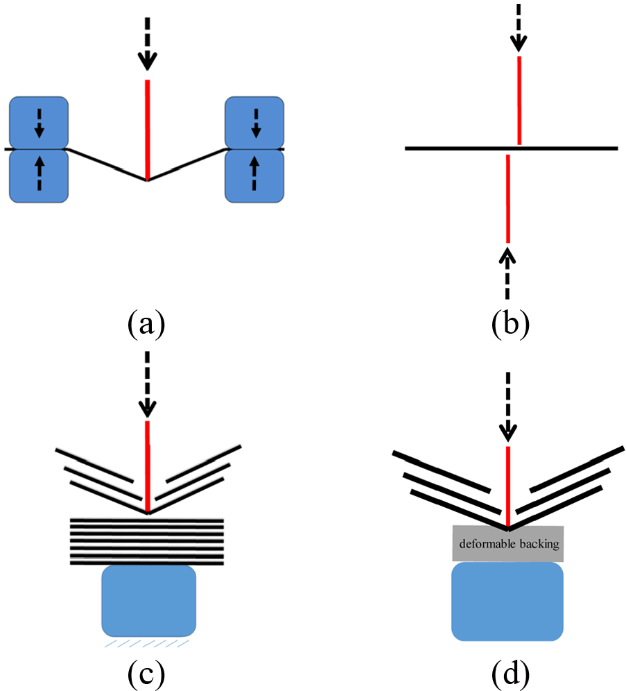
Principal carbon fiber severing mechanisms (red: blade; black: carbon filaments/tows; blue: support): (a) unsupported/unbacked bending, (b) shearing, (c) crushing, and (d) supported/backed bending.
In common high-throughput composite manufacturing—such as in the case of sheet molding compound (SMC) technology—chopped fibers (regardless of whether glass- or carbon-based) fall under their own weight directly on the polymer sheet used to transfer them to the next manufacturing process to be carried out in the composite fabrication sequence. However, preliminary tests revealed that while most of the existing fiber cutting systems perform reasonably well on glass, this is not the case for carbon fibers. On the other hand, a visual inspection of their appearance reveals significant differences between the morphology of the two types of tows in a sense that unlike glass (Figure 2), carbon fibers tend to separate somewhat easier into finer filaments most likely because they are delivered in the form of untwisted rovings. This dissimilarity—responsible for a special type of behavior under the cutting load—combined with many others originating from their distinctive mechanical properties makes the entire mechanics of failure for carbon fibers completely different from that of their glass counterparts. As such, in addition to the clogging and jamming of the chopper20,21—which is somehow predictable in the context of high-throughput rates intended for SMC lines—the preliminary tests performed have suggested higher blade wear rates as well as higher cutting forces are required to induce the fracture of the carbon fibers. Recent work in the area of carbon fiber severing has shown that high wear rates of the cutting blades are common due to the abrasive nature of the fibers, 23 the predominant mechanism of severing is flexural fracture, 24 and less rigid/elastic backing is preferable. 25 However, none of the prior studies focused on the severing of the carbon fiber bundles have proposed metrics capable to enable direct quantitative comparisons of the particular blade/backing combination used during the severing process.

Significant differences between the morphology of carbon (left) and glass (right) tows.
As it becomes evident, while the need for durable and high-throughput carbon fiber solutions is present, a relative lack of systematic and knowledge-based studies exists on the topic of carbon fiber cutting mechanics. As one of the first steps in this direction, the main objective of the current study was to develop and validate a carbon fiber severing apparatus capable to provide insight on the cutting forces developed at the cutting blade/carbon fiber interface.
Preliminary considerations
Generalities on carbon fibers
Carbon fibers—consisting of roughly 90% weight carbon—are obtained through the pyrolysis of an appropriate polyacrylonitrile (PAN) or pitch precursor. 26 At the atomic level, the structure of carbon fiber consists of sandwiched and intermixed graphene layers held together by weak van der Waal’s forces and separated by approximately 0.335 nm. 27 The most desirable properties of carbon fibers are their high tensile modulus, high tensile strength, low density, high thermal stability and conductivity, as well as excellent creep resistance. However, while carbon fibers have notable tensile properties, their compressive strength plays an important role on their severing mechanism.
The highly ordered planar carbon sheets that contribute to carbon fiber’s high strength are also the main contributor to its anisotropy. By contrast, glass fibers are generally regarded as being characterized by an isotropic structure.
28
However, both types of brittle fibers have been shown to break in bending when reaching a critical radius of curvature that can be approximated, for isotropic materials, as
Loop test
The elastica loop test, or simply loop test, was one of the first experimental methods used to determine the critical bending radius of the fibers. According to this technique, a fiber loop or knot is sandwiched between the glass slides of optical microscope and its two loose ends are pulled in opposite directions (Figure 3(a)) until the fracture occurs. 28 If the entire process is recorded at reasonably high speeds/resolutions, then the critical radius can be estimated with sufficient accuracy (Figure 3(b)).
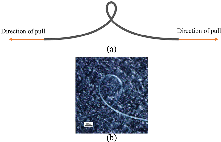
Elastica loop test: (a) working principle and (b) example of a last frame captured prior to the fracture of anE-glass fiber.
The preliminary loop tests performed in triplicate have indicated that while the critical radius of the Torray 12k T700S carbon fibers is 61.3 ± 5.0 µm, Johns Mansville Multistar 272-2400-80 (JM272) E-glass fibers will break at a radius of 161.0 ± 36.9 µm. On the other hand, theoretical calculations involving the measured diameter of the filaments, namely, 7.1 ± 0.4 µm for carbon and 13.7 ± 0.1 µm for glass, will yield critical radii of ∼165 µm and ∼160 µm for the two types of fibers, respectively. The required material properties were assumed in the reported ranges, namely, Ecarbon = 230 MPa, σcarbon = 4.9 GPa 29 and Eglass = 75-80 MPa, σglass = 2–3.8 GPa.30,31 The comparison between experimental and theoretical approaches reveals that while the match is almost perfect for glass, this is no longer the case for carbon fibers for which the experimentally determined critical radius is roughly one-third of its theoretical counterpart. While many factors could be responsible for this behavior, it is reasonable to assume that the anisotropy of carbon fibers 28 plays a significant role.
Preliminary experiments
In order to make a preliminary assessment of different techniques that can be used in carbon fiber severing, the aspect of fiber’s end was scanning electron microscope (SEM)-imaged and the micrographs presented in Figure 4 show distinctive differences between them, in a sense that the cleanest cut is typically obtained when the filaments are being bent to their critical radius (Figure 4(a), mechanism corresponding to Figure 1(a)–(d)).
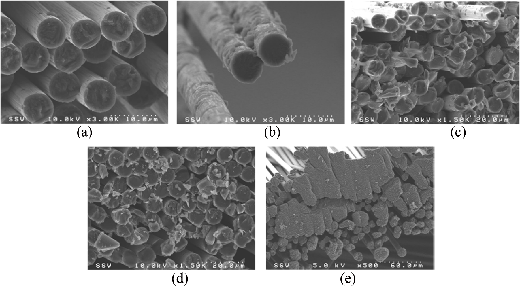
Aspect of carbon fiber end after different modes of failure: (a) loop test, (b) tensile test, (c) scissors cut, (d) crush cut, and (e) laser cut.
Reasonably clean ends are also obtained in tension, although a certain delamination/excoriation of the external sizing is also visible. As a side note, the sizing applied on the commercial carbon fibers is of proprietary nature, its primary role being to enhance the bonding between the matrix and fiber, thereby enhancing the mechanical properties (i.e. compressive strength and interlaminar shear strength) of the final composite material. Polymeric sizing is also applied to alter fiber protection, fiber alignment, and fiber wettability. 32 However—from a strict fiber severing perspective—the presence of sizing on the surface of the fibers adds a whole new layer of challenges, primarily due to the unknown/little known composition/properties of the sizing used.
Moving away from the “clean” bending to a critical bending radius that can be achieved with (Figure 1(d)) or without (Figure 1(a)) backing, fibers can also be cut/severed with handheld scissors (Figure 4(c), mechanism in Figure 1(b)) by pushing a sharp blade into tow of fibers that is placed on a hard surface (Figure 4(d), corresponding mechanism in Figure 1(c)) or through laser machining/ablation. However, a large amount of hazardous carbon dust/particles will be generated when crushing/severing is present (and this will also affect chopper performance in addition to being a health risk), while the inherent fiber end welding/bonding associated with thermal processes will likely hinder a uniform dispersion of the chopped fibers onto the carrier SMC film.
All in all, the preliminary trials performed seemed to—perhaps unsurprisingly—imply that the available commercial solution relying on backed/unbacked bending of the carbon fibers to their critical radius is also the one to yield a better/superior appearance for the carbon fiber end. Without being able to draw—at this time—definite conclusions that will constitute in fact the subject of future investigations, it could be rather speculated here that the presence of a somewhat soft(er) backing would force the carbon fibers to better/faster comply with the shape of the blade and therefore break/separate easier (Figure 5).
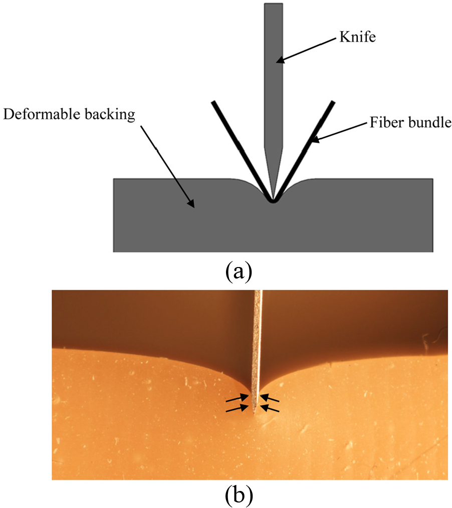
Effect of the deformable backing on the bending of the carbon fibers: (a) schematic representation and (b) physical in-process depiction (no fibers, Shore 42A backing).
Linear cutter design
Assembly structure
In order to be able to investigate the behavior of the carbon fiber bundles subjected to cutting conditions, an experimental apparatus has been developed with several design requirements in mind, as follows: (1) mount severing blades of varying geometry, (2) mount backing components of varying geometry and hardness, (3) apply a controlled fiber tension force, (4) plunge the blade into the carbon bundle/backing at different velocities/feed rates, and (5) establish accurate correlations between the amount of cutting force generated during fiber severing and the vertical position of the blade.
While other functionalities were also considered during the initial conceptual phases, they had to be eventually eliminated due to the current lack of appropriate and/or feasible technological means to materialize them. For instance, while it would have been important to add the number of severed filaments to the correlations outlined at point (5), it was found that no reliable method exists (yet) for this purpose in a sense that even if carbon fibers are typically conductive (i.e. by leaving aside the additional unknowns/challenges introduced by filament sizing), the electrical noise generated during blade penetration tends to overcome the current passed through the carbon filaments. Furthermore, while the quantification of the backing deformation would have been another important metric to be added to the same correlations, the absence of a direct line of sight to the cutter/fibers/backing contact zone made this assessment virtually impossible at this time.
Based on the design constraints outlined above, the overall design for the linear cutter is presented in Figure 6. While the facile interchangeability of blade and backing as well as the adjustable fiber tension was relatively easy to implement in the design, the controlled plunge motion of the blade was achieved by attaching the device mount to the spindle of a computer numerical control (CNC) mill. The mount had to be switched from a conductive to a non-conductive material because of the noise that was originally introduced into the cutting force measurement. As shown in Figure 6, the linear variable differential transformer (LVDT) holder was positioned below the load cell such that the displacement captured by the LVDT would not include the deflection of the load cell. To minimize the confounding inertial/vibrational effects, the LVDT holder was fabricated from aluminum.
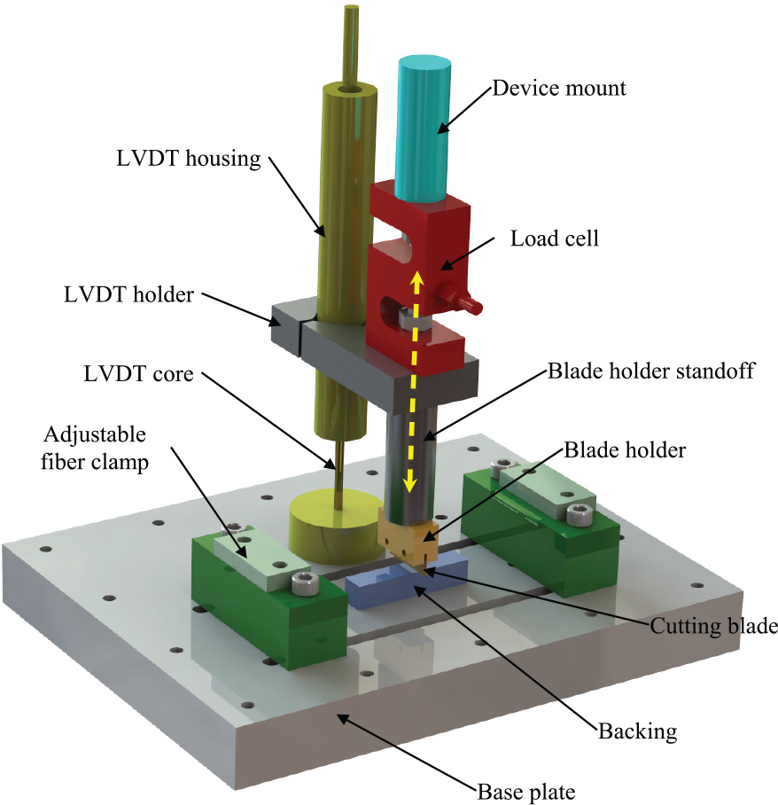
Overview of the linear cutter design.
During the normal operation of the linear cutter, the carbon fibers placed on top of the backing (and possibly fixtured with fiber clamps) are being severed as a result of the downward motion of the subassembly comprising the device mount, load cell, blade holder, blade, and LVDT housing. Once the subassembly retracts, a new bundle of fibers can be installed for the subsequent cutting test. While the idea of an automated fiber feeding system was initially considered for the linear cutter, it was later eliminated since this would have brought significant design complications/cost that have been addressed through a switch to a rotational fiber severing system that is, however, very difficult/impossible to instrument.
Data acquisition system
To enable the measurement of the cutting forces and blade positions (design constraint (5)), an Omega LC101-25 strain gauge-based load cell along with a Measurement Specialties HR500 LVDT was integrated into the construction of the linear cutting device. According to the manufacturer’s datasheets, the load cell is characterized by a linearity of ±0.03%, a repeatability of 0.01%, and hysteresis of ±0.02%, while the LVDT has a ±12.7 mm displacement range. Both load cell and LVDT were calibrated prior to their first use. A universal conditioning module from Penny and Giles was used for the analog-to-digital conversion.
The overall design of the data acquisition system is presented in Figure 7(a). Data acquisition was carried out by a National Instruments USB-6210 card characterized by a 16-bit resolution and 250,000 samples logging capabilities. A Labview-based graphical user interface was developed to enable the facile monitoring and collection of the data (Figure 7(b)). The sampling rate was chosen at 15 kHz, a frequency that is much higher than the minimum recommended by the sampling theorem (“twice the rate of the highest frequency content”). The rationale behind this decision resides in the fact that a higher sampling rate would enable a superior preservation of the high-frequency content, should this become of interest in the subsequent signal processing stages. Moreover, higher sampling rates would reduce the chance of data aliasing and even though the amount of data collected was significant, it could be processed in a reasonable amount of time on midrange computing equipment (i.e. under 10 s/trial cut).
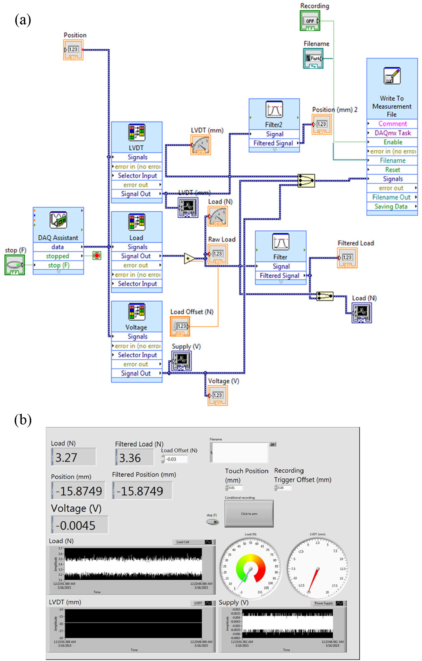
Data acquisition and signal processing system: (a) overview of the data processing flow and (b) graphical user interface.
Natural frequency
One of the drawbacks of the developed design solution is represented by the presence of the heavy load cell that has the potential to become excited during the routine data acquisition process and therefore confound the results. As such, one of the first steps undertaken was to determine the natural frequency of the system. For this purpose, the CNC-attached apparatus was excited through tapping, and Fast Fourier Transform (FFT) analysis showed a natural frequency of 201.7 Hz for the system without backing installed (Figure 8). Similar values were obtained when backing was installed (201.1 Hz) and when the system was excited with known excitations generated by a voice coil used to incrementally sweep the entire spectrum between 1 and 250 Hz (202.2 Hz).
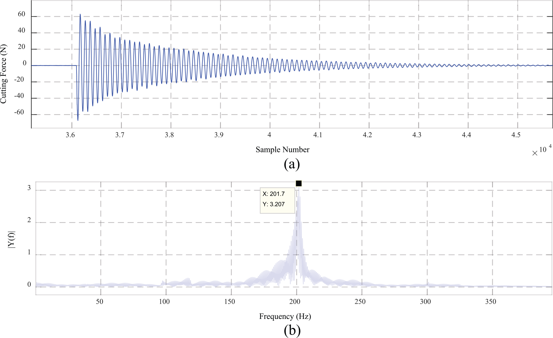
Frequency response of the developed system under free vibration conditions: (a) time domain signal and (b) frequency domain signal.
Signal processing
One of the common challenges in signal processing is related to the selection of an appropriate filter as—very often—the boundaries between “too smooth” and “not smooth enough” are more or less an instance of an ill-defined problem, particularly in case of newly developed experimental devices and/or technologies. The developed linear cutter was no exception, and Figure 9(a) shows a sample of raw cutting force data acquired during the preliminary trials in which large oscillations at natural frequency occur after the blade completes the severing of the bundle (= the large drop in the cutting force, to be detailed further, below). As such, the determination of an appropriate filtering method constituted an important task.
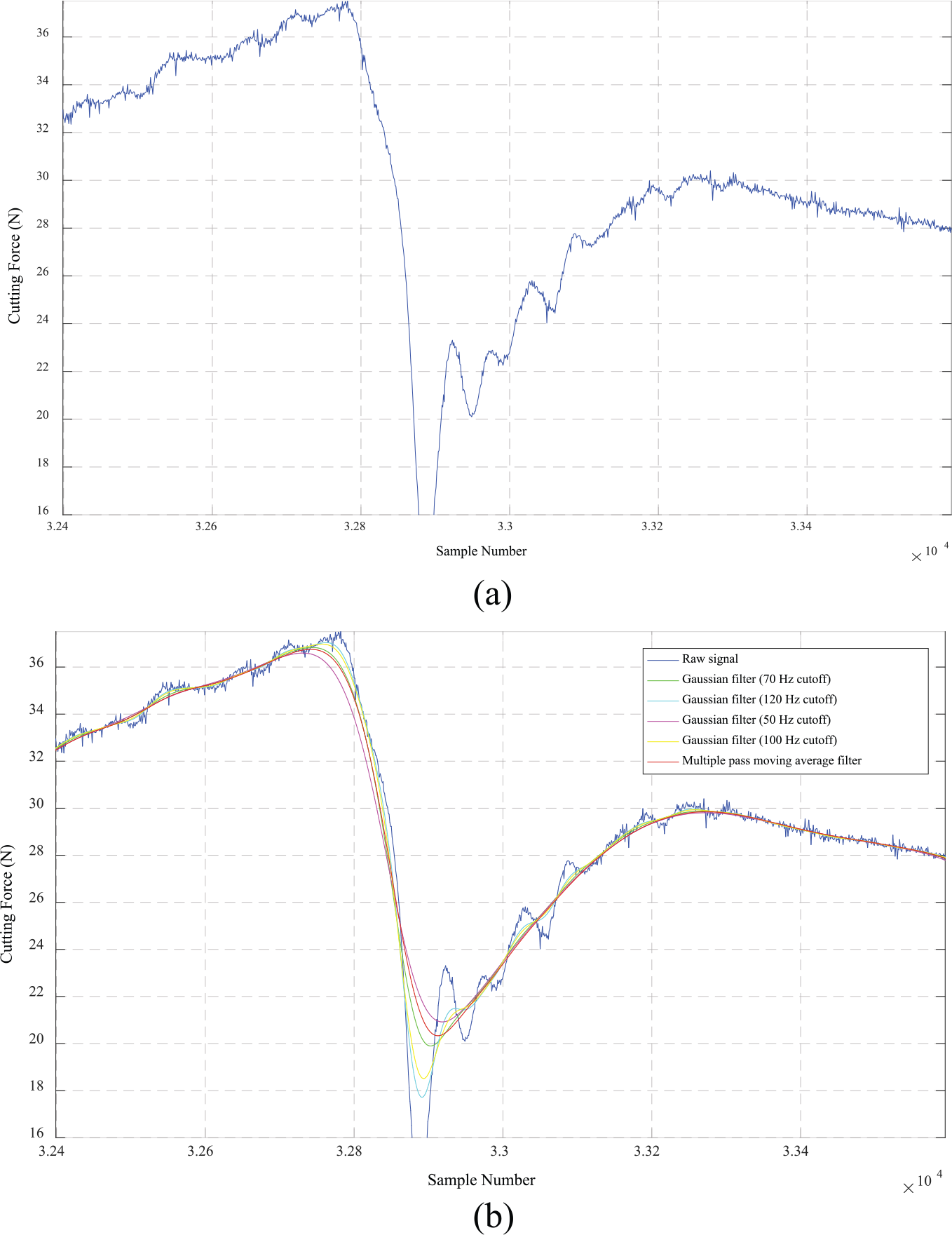
Application of adequate filtering to eliminate data noise: (a) raw measurement signal and (b) output of different filtering techniques.
Heuristic searches were performed to determine an adequate filtering method that would not eliminate—through (over)smoothening—signal with physical relevance. While the differences between the filters tested (Figure 9(b)) are relatively minimal, multiple pass moving average was selected based on its robustness and its pertinence to the subsequent peak-finding techniques. Without entering excessive implementation details provided in the relevant literature, 33 it will be briefly reminded here that the moving average filter commonly shifts the signal in time domain by also reducing the amount of data points in the filtered data. However, the signal itself is not scaled in a sense that the number of data points within a given time period remains the same both in raw and filtered signals.
The multiple pass moving average filter—the enhanced version of the common moving average algorithm—alters—through successive passes—the kernel filter from a rectangular to a Gaussian shape. Because the shape of the filter kernel is not rectangular, samples in the input signal that are further away from each other have a smaller impact on the filtered signal than those that are closer to each other. As an important observation, the multiple pass moving average is more computationally efficient than the Gaussian filter. Based on all these considerations, the raw data were processed with a five-time pass moving average filter relying on a 50-point window that is approximately equivalent to the 70 Hz cutoff Gaussian filter. To accurately and consistently determine the location of the process-significant points on the cutting force–displacement curves recorded with the experimental apparatus, a robust peak-finding algorithm was developed in MATLAB (Figure 10).
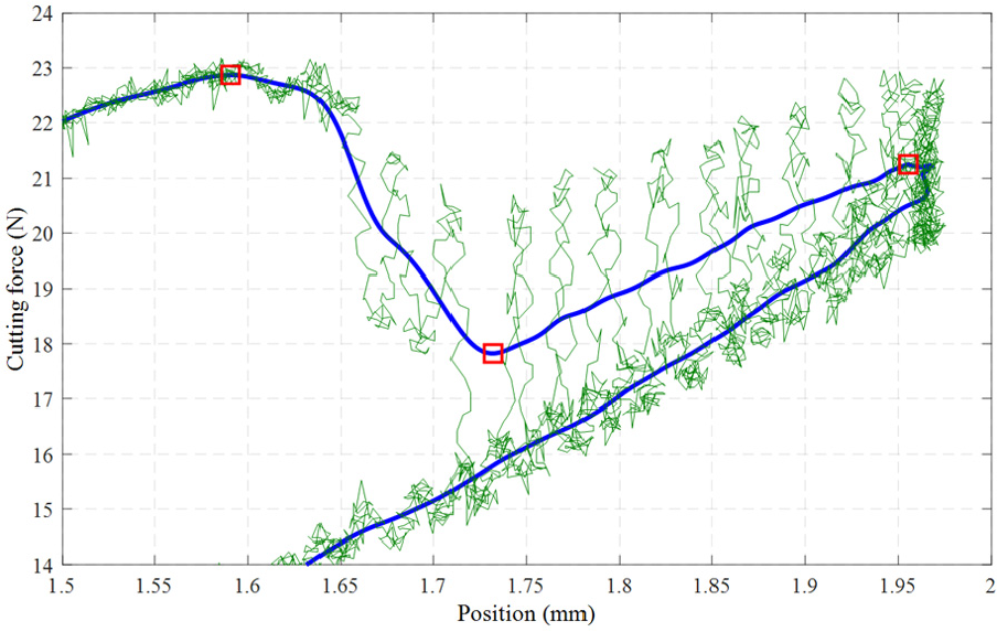
Sample of peak-finding results (red squares).
Experimental protocol
Before each cutting trial/set of cutting trials, a rigorous setup procedure was followed in order to ensure the consistency and accuracy of the recorded data. More specifically, for each combination/pair of blade and backing—that could vary in terms of geometry and material—the preliminary setup procedure consisted of the following basic tasks: (1) set position datum, (2) determine the maximum plunge depth, and (3) collect a baseline force–displacement curve without severing fibers.
In terms of the rationale behind these operations, it should be noted here that the common position datum allows direct graphical comparisons between experiments regardless of fiber tow size or backing height. Furthermore, the maximum plunge depth was determined by running the severing blade in the manual control mode in the presence of fibers, the goal being to ensure that the machine-driven experiment will successfully cut the entire bundle without much overshoot (i.e. by plunging too deep into the backing) that could confound the results. Finally, the collection of the baseline force–displacement curve facilitates determination of the work to cut fibers that was not directed toward the compression of the backing.
The height of the datum was experimentally determined by manually lowering the blade until it contacts the backing, a moment associated with small load signal increases (∼0.1 N) that is equivalent to a maximum positional error of ±0.03 mm. While this error affects—to a certain degree—the accuracy of certain experimental parameters (such as fiber tow height or maximum plunge depth), it will not have a major impact on work calculations or cutting force measurements.
Once the datum of the cutting operation has been set at the top of the backing, the maximum plunge depth required to achieve the complete severing of the bundle was determined by manually driving the blade into the tow until a sharp drop in the load signal occurred. While the corresponding displacement represents the sought-after parameter, a small overshoot of 0.25 mm was added to ensure the complete separation of the bundle. The predetermined maximum plunge depth was used as the endpoint of the CNC-programmed severing motion of the cutting blade.
To ensure the repeatability and the statistical significance of the recorded data, all cutting trials—both with and without fibers—were performed in triplicate. Furthermore, the experimental data points with cutting forces under 0.35 N were removed to accurately delimit the beginning and the end of the cutting trial as timestamps that essentially correspond to non-contacting conditions between blade and backing.
Experimental results
Characteristic curve
A characteristic force–displacement curve generated with the developed linear cutter is depicted in Figure 11. As it can be noticed, the initial slightly nonlinear dependence between the cutting force and displacement is succeeded by a quasi-linear region that corresponds to the continuous advancement of the blade into the bundle of fibers that is sandwiched between the blade and the backing. While no certainties can be provided for the initial nonlinear dependence, it would be reasonable to assume that the initial compaction/settling of the fibers under the action of the blade could be the source of the observed nonlinear pattern.
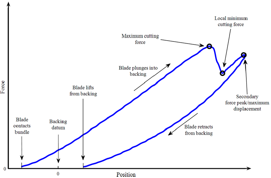
Sample of a characteristic curve generated with the developed linear cutter.
The drop in cutting force that follows the peak cutting force coincides with the severing of the fibers in the bundle. However, once the backing recovers from the deformation corresponding to the thickness of the bundle, it starts pushing again into the blade and this creates the secondary force peak that is achieved at the maximum plunge depth/peak displacement. The incremental change in the position of the blade between the local minimum of the cutting force and its secondary peak corresponds to the aforementioned overshoot distance/motion. Once the blade starts to retract/move upward, the load starts to decrease in a nonlinear manner and it reaches a null value before the blade arrives at the datum (i.e. top of the backing) level. The discrepancy between the initial datum and the final null force position can be attributed to the viscoelastic nature of the backing material.
Fiber severing metrics
The aforementioned characteristic curve enables the definition of several metrics to be used to compare the behavior of different blade/backing/fiber combinations in the context of the developed linear chopper. Among them, roving height represents the length of the negative segment of the position/X-axis since the datum has been set at the top of the backing (Figure 12(a)). Conversely, the travel of the blade up to the cutting force minimum represents the depth to cut fibers. Finally, the work to cut fibers includes both a component directed toward fiber severing as well as one directed toward backing deformation. Furthermore, the total work required during fiber severing process is depicted in Figure 12(b), whereas Figure 12(c) illustrates the work to deform backing that was derived from a characteristic curve obtained in the absence of fibers. While it might not be apparent, the total work tends to be smaller than the work to cut fibers since the former includes a negative component generated through the recovery of the backing during the post-severing upward retraction of the blade.
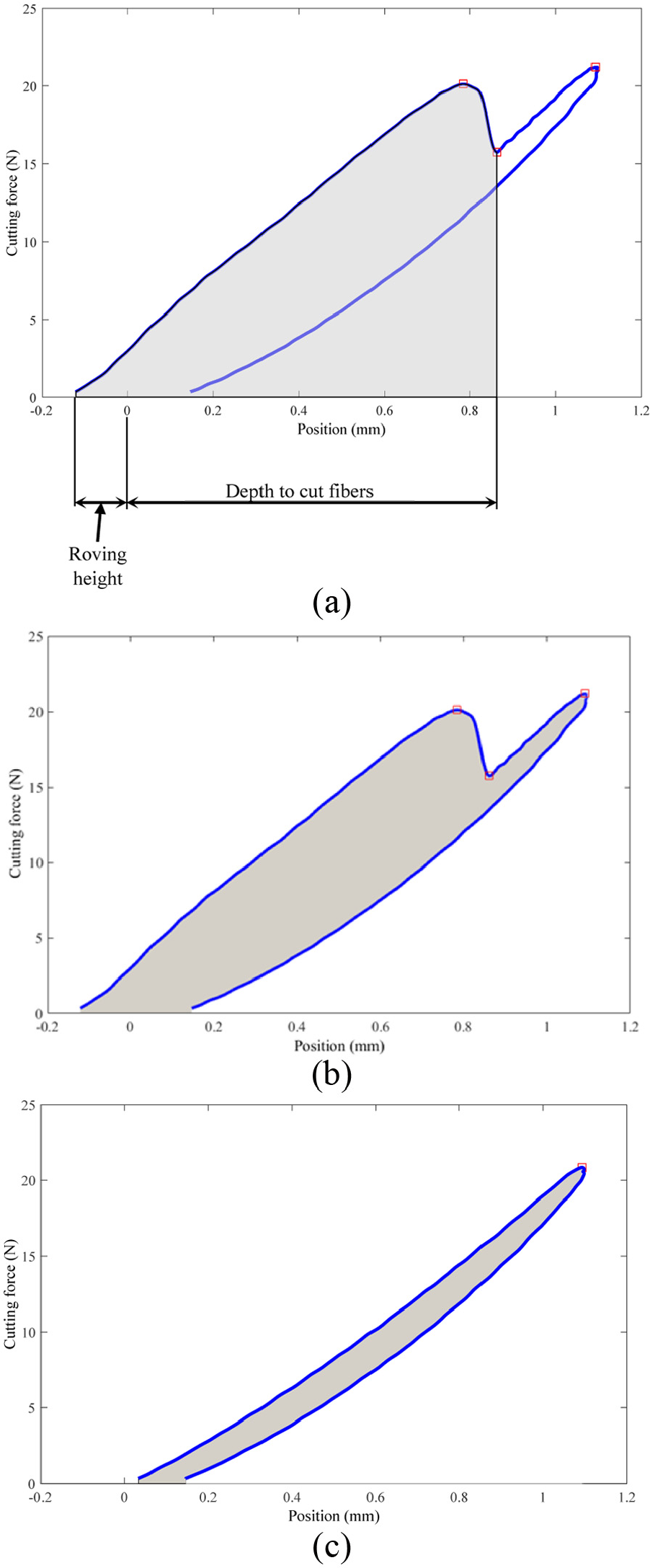
Graphical depictions of the fiber severing metrics: (a) roving height, depth to cut, and work to cut fibers; (b) total work; and (c) work to deform backing.
Sample effect of fiber/backing combination on characteristic curve
To test the capabilities of the developed linear cutter, a number of severing trials were performed with different combinations of fiber materials and backing combinations (Figure 13) while the blade and its cutting velocity/feed rate (7.5 ipm) were kept the same. The two representative types of commercial fibers used were JM272 (E-glass, 2400 tex, 13.5 µm filament diameter) and Toho Tenax STS40 F13 (carbon, 1600 tex, 24k filaments/bundle, 7 µm filament diameter), the primary concern used in their selection being to maintain a comparable cross-sectional area between the two types of bundles. Both types of fibers have recommendations for high-volume automotive applications, typically in the context of SMC manufacturing technology.
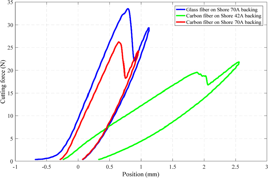
Characteristic curves for different fiber/backing combinations.
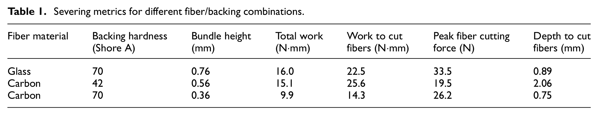
The results of the experimental trials were numerically summarized in Table 1. As it can be noticed, a 27% increase in the peak cutting force is associated with glass fibers, even when placed on the same backing as their carbon counterparts. Furthermore, softer backings tend to reduce the peak severing forces along with the total work required during severing, whereas the depth and work to cut fibers tend to increase for this particular fiber/backing combination. While comparable levels of the peak cutting force were reported in Xie et al. 24 and Lu et al., 25 direct side-to-side comparisons are difficult and likely incorrect due to a number of experimental factors that were different between the studies (e.g. fibers, blades, severing procedure, etc.).
Severing metrics for different fiber/backing combinations.
Sample effect of blade sharpness on characteristic curve
To assess the effect of blade wear on the characteristic curve, a set of four steel blades that are commonly used on a commercial SMC-line fiber chopper were “artificially dulled” by means of electrical discharge machining (EDM), in a sense that they were produced with cutting edges characterized by gradually increasing radii (Figure 14). While the SEM images suggest that the quality of the EDM output is somewhat questionable in terms of geometric accuracy and surface roughness, it is also clear that the sharpness of the four blades decreases as the radius of the cutting edge increases.
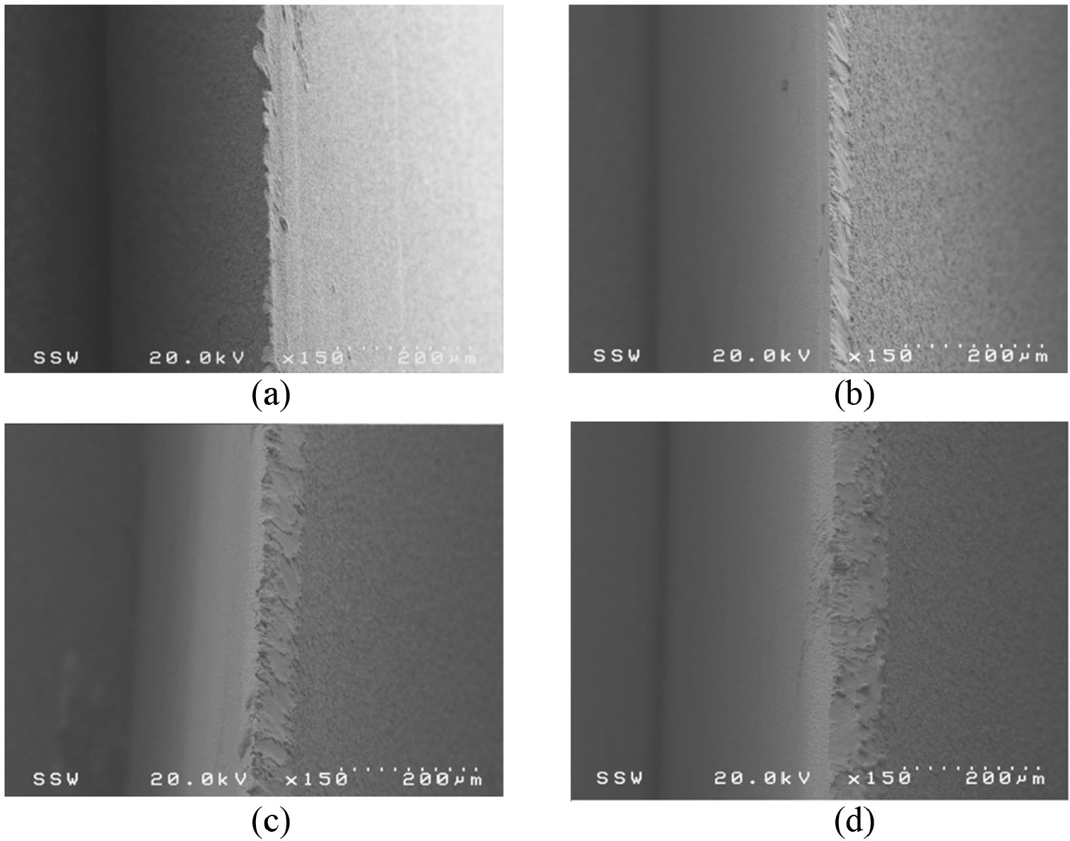
SEM micrographs of artificially dulled blades at (a) 20 µm, (b) 40 µm, (c) 60 µm, and (d) 80 µm target cutting edge radius.
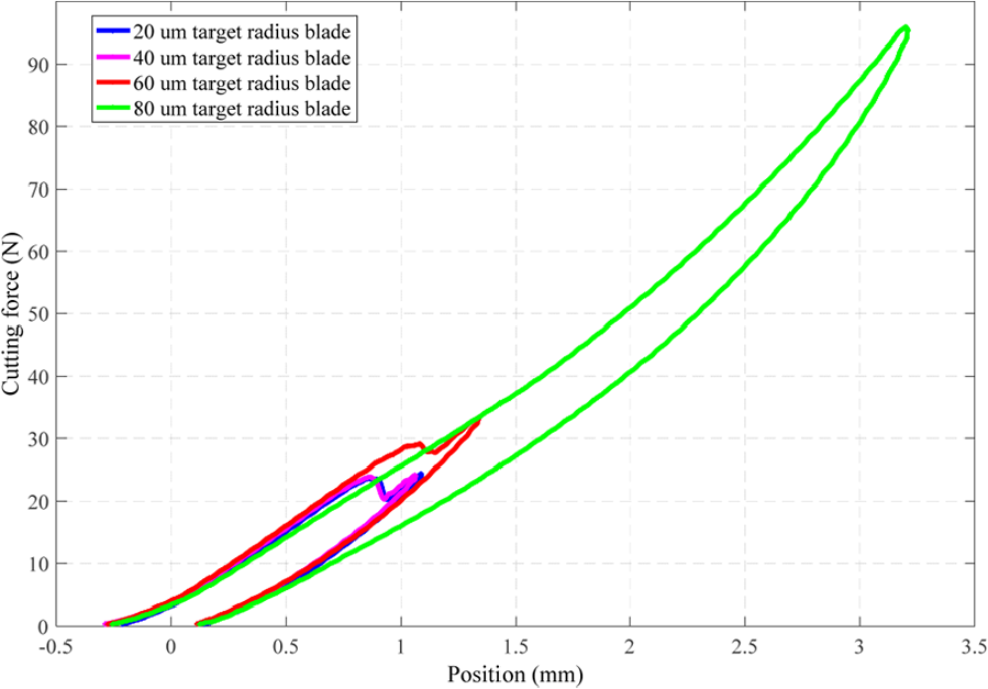
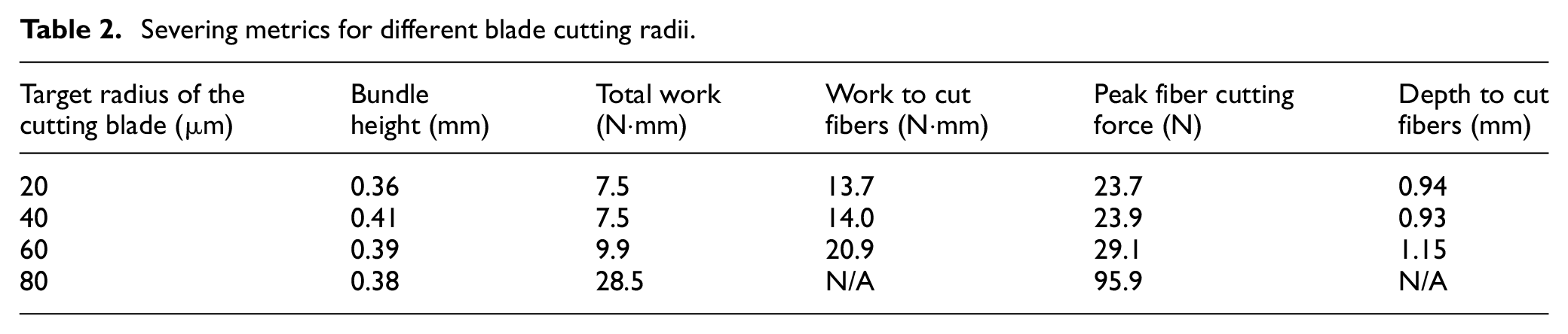
The measurements performed with the instrumented linear cutter are graphically presented in Figure 15 and summarized in Table 2. All four cutting trials were conducted with the same carbon fiber/backing combination (i.e. Toho Tenax STS40 F13/Shore 70A backing) while maintaining the same blade cutting velocity (7.5 ipm). The recorded data show that while a minimal change exists between the characteristic curves associated with 20 and 40 µm target edge radii, a 21% increase in peak cutting force and a 50% increase in work to cut fibers are caused by the 60 µm blade radius. On the other hand, the 80 µm blade radius was unable to completely sever the bundle, such that the plunge depth was limited to 3.2 mm in order to prevent larger than 96 N loads that could potentially damage the load cell. Evidently, when cutting is performed with duller blades, more energy and longer travels are required in order to ensure the complete severing of the carbon fiber bundle. Conversely, as long as the sharpness of the blades remains under a certain threshold—that is likely related to the critical bending radius of the carbon filaments—no significant difference exists between their cutting performances. Same as above, while some of these findings were partially echoed by the previous studies,24,25 it is believed that it would be borderline speculative to perform direct comparisons and/or extrapolations between data that were acquired by means of different experimental setups.
Characteristic curves for blades with different sharpness.
Severing metrics for different blade cutting radii.
Conclusion
As intended, the novel prototypical linear cutter developed in the context of this study was shown to be capable to track the dependence between cutting force and position of the blade during the severing of the fiber bundles. The major contributions of this study are related to the development, testing, and validation of (1) an instrumented linear cutting device capable to concurrently monitor the fiber severing force and the travel of the blade, (2) a fiber severing protocol meant to ensure the consistency and repeatability of the readings, and (3) a signal processing capable to conservatively remove the noise caused by the vibration of the entire fiber severing system. Building on this, this study has demonstrated that characteristic curves generated by the developed linear cutting device can be used to accurately and quantitatively compare the performance of a specific cutting blade/backing combination, even when used in context of different severing process parameters.
The initial investigations conducted with the instrumented linear cutter have demonstrated that the type of the fibers to be cut, sharpness of the blade, as well as the hardness of the backing are all factors with a major influence on the characteristic curve and hence they should all be used to optimize the efficiency of the fiber severing process. More specifically, up to 27% increase of the peak cutting force can be observed when carbon fibers were substituted with glass fibers, while using backing of the same hardness. As anticipated, the prototypical linear cutter was able to detect that increases of up to 21% of the peak cutting force might be required when blade edge radius increases from 20–40 µm to 60 µm, whereas a “completely” dull blade (80 µm radius) is in fact unable to cut.
Future research efforts will integrate the linear cutting device in a systematic study aiming to establish correlations between the parameters affecting the performance of the fiber cutting process, the longer term goal of this work being to establish a technically sound basis/baseline for the upcoming developments in the area of high-volume fiber cutting technology.
Footnotes
Acknowledgements
The authors would like to acknowledge the technical contributions brought to the project by Tobias Potyra (Fraunhofer Project Center/Karlsruhe Institute of Technology), Clayton Cook (University Machine Services, Western University), Ross Davidson (Surface Science, Western University), and Dave Lunn (Mechanical and Materials Engineering, Western University).
Declaration of conflicting interests
The author(s) declared no potential conflicts of interest with respect to the research, authorship, and/or publication of this article.
Funding
The author(s) disclosed receipt of the following financial support for the research, authorship, and/or publication of this article: The authors would like to acknowledge the financial support provided in part by Ontario Centers of Excellence and Dieffenbacher North America.