
Abstract
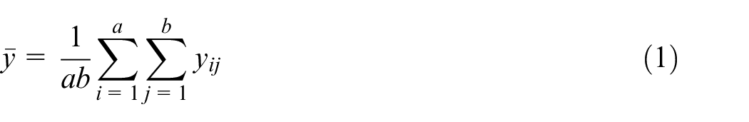
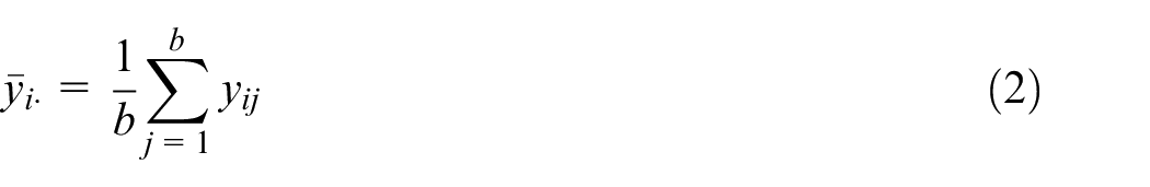
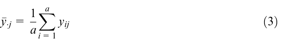
Countersinking process introduces variations in the angle and depth of the countersunk hole due to the wearing down of the drilling bit and the specific properties of carbon fiber–reinforced plastic/polymer part. The ultimate tensile strength of the countersunk bolted composites is affected by the countersinking depth and angle. The article presents a numerical and experimental investigation on the effect of countersinking depth and angle on the tensile strength of the single-bolted countersunk joint. Numerical bolted models with designed depths and angles are constructed to predict the tensile strength. Nine experimental specimens are fabricated according to the ASTM-D5961 standard, and the experimental results validate the proposed numerical models. Analysis of variance is used to investigate the synergistic effect of the countersinking depth and angle on the ultimate tensile loading. The analysis of variance result shows that the countersinking depth should be strictly controlled. The relationship between the tensile strength and the depth of the countersunk hole is obtained by the validated numerical models, and the relationship could be used to allocate the tolerance of the countersunk holes. The reported work provides reference for precision countersinking in the composite bolted joint and help systematically in improving the precision strength prediction of the countersunk bolted joint in composites.
Keywords
Introduction
Countersunk bolted joint is an important connection used in the carbon fiber–reinforced plastic/polymer (CFRP) structures. Many numerical and experimental studies1–10 on the bolted joint of composites have been conducted to investigate the effect of bolting parameters on the joint strength, load transfer and distribution, and so on. The bolting parameters that have been studied include design specifications, hole position variations, fiber/resin properties, laminating sequences, coefficients of friction, bolt–hole clearance, bolt–hole interference, and the clamping force. These studies1–10 are analyzed and calculated with nominal dimensions and nominal material parameters. There are a lot of random errors, that is to say variations, during the course of actual production in fact. These variations affect the performance of bolted connections. Tolerance is the extent of the variation that varies. Good tolerancing of the dimensions assures the connection quality and production efficiency.
Before bolted connection, the hole is drilled at first. There are variations in the drilled hole, for example, the variation in hole diameters. 11 Countersinking process introduces variations in the angle and depth of the countersunk hole due to the wearing down of the drilling bit and the specific properties of CFRP part. 12 Although the countersinking process can be optimized using drilling-data-based compensation, variations in the countersunk hole occur. Dimensional variations in the countersunk hole affect the fit condition between the bolt and the hole, and consequently affect the tensile strength of the bolted joint. The stresses around the countersunk hole are complex due to the complex contacting mechanism between the countersunk bolt head and the fiber/resin in the walls of the countersunk hole. Inadequate tensile strength prediction leads to inefficiency of strength and weight in aircraft structures.13–16 The dimensional tolerance of the countersunk hole needs to be allocated precisely in order to accomplish the bolted joint requirements (Figure 1).
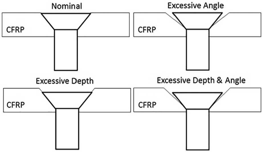
Dimensional variations in the countersunk hole.
The article presents a numerical and experimental investigation on the effect of countersinking depth and angle on the tensile strength of bolted joint. After discussing the most relevant literature, numerical models of the bolted joint are constructed to predict the tensile strength. Experimental specimens are fabricated according to the full factorial design method and the ASTM-D5961 standard. Experimental result is employed to validate the proposed numerical models. Analysis of variance (ANOVA) is used to investigate the synergistic effect between the depth and the angle. Intensive finite element analysis (FEA) models with designed depths are calculated to obtain the relationship between the depth and the tensile strength. Control limits of the countersinking depth are determined based on the obtained relationship.
Literature review
Dano et al. 1 developed a two-dimensional FEA model to study the strain and stress in the pin-loaded joint in composite. The failure criteria, combined with the degradation rules, were the main concern. Park and Grandt 2 conducted numerical and experimental study on the cracking behavior around the countersunk joint. Low/high load transfer tests and fatigue test were conducted. Ekh and Schön 3 investigated the effect of design parameters and clearance on the load distribution in multi-fastener joints. A hybrid composite laminates with titanium plies was developed in order to improve the load capacity of joints. Camanho et al. 4 studied the bolted joints’ behavior under different percent of titanium sheet in the composite laminates. Hühne et al. 5 proposed a three-dimensional (3D) finite element model to study the structural behavior of bolted joint with a liquid shim layer. And Hashin’s failure criterion was employed.
McCarthy and colleagues6–10 conducted a series of studies on composite bolted joints. Theoretical modeling, analytical modeling, numerical modeling, and load distribution were intensively studied and reported. Olmedo and Santiuste 17 proposed their failure criteria based on Chang–Lessard criteria to predict the failure in bolted joints. Stress concentration is an important influence factor for load transfer and progressive failure. Stress concentration factor (SCF) is used to predict the load transfer and progressive failure, and so on. Darwish et al. 18 developed a modified equation to calculate the SCF for high accuracy in countersunk joint. Liu et al. 19 constructed a 3D finite element model of hi-shear fastener in composite-metal joining. Effects of bolt–hole neat fit, interference fit, and clamping force on the maximum loads were studied based on the numerical model and experimental results.
Static and dynamic behaviors are two aspects of the bolted joints’ behavior. Besides the static behavior, Heimbs et al. 20 presented their study on dynamic behavior of countersunk bolts also. Lecomte et al. 21 tried to use analytical modeling method to calculate the load distribution among multi-bolt double-lap joint in composite-metal joining. Compared with the laminated composites, woven carbon composites are also widely used. Warren et al. 22 presented their study of bolted joint in 3D woven carbon composites and experimental results. Cheng et al. 23 proposed their novel designed π-joint for composite bolted joining. Kader et al. 24 studied the effect of position error on the strength of bolted joint. Numerical results of the bearing type joints with two, three, and four rows of bolted connections were reported. Wang et al. 25 studied the tolerance optimization method for the countersunk hole using the Digital Twin of the bolted joint.
Numerical model of bolted CFRP
Because the depth and angle variations are in three dimensions, the two-dimensional numerical model is not enough for stress analysis. A 3D numerical model of the countersunk bolted joint is constructed in ABAQUS based on the ASTM-D5961. The bolted CFRP with countersunk hole is shown in Figure 2, which consists of 7075 Aluminum, CFRP laminate, and the countersunk bolt.
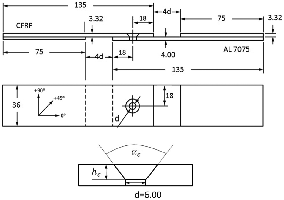
Countersunk bolted specimen (all dimensions in mm).
The CFRP laminate is meshed with the C3D8R continuum 3D brick elements, and it results in 3900 nodes and 3100 elements approximately (Figure 3). The 7075 Aluminum is meshed with the C3D8R continuum 3D brick elements, and it results in 410 nodes and 168 elements. The countersunk bolt is meshed with the C3D8R continuum 3D brick elements and six-node, solid C3D6 continuum 3D elements, and it results in 2814 nodes and 2600 elements. The nut is meshed with C3D8R continuum 3D brick elements, and it results in 480 nodes and 240 elements. The washer is meshed with C3D8R continuum 3D brick elements, and it results in 240 nodes and 80 elements.
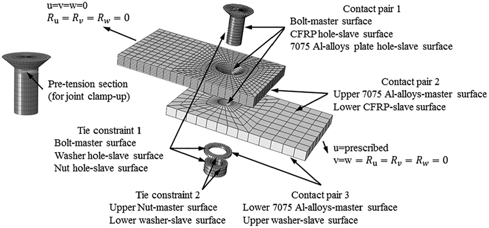
Numerical model with boundary conditions.
The following rules are applied when setting the master–slave surface: the slave surface is a finer mesh surface; if the mesh densities are similar, the slave surface should be taken from a surface that uses a softer material. There are contacting mechanisms between these interfaces: (1) the bolt surface and the CFRP countersunk hole, (2) the bolt and the one-piece 7075 Aluminum hole, (3) the lower CFRP laminate surface and the upper 7075 Aluminum surface, and (4) the lower 7075 Aluminum surface and the upper washer surface. The bolt surface and the one-piece 7075 Aluminum surface are chosen as the master contact surfaces, while the CFRP hole, 7075 Aluminum hole, lower CFRP surface, and the upper washer surface are chosen as the slave contact surfaces. The surface-to-surface contact definition is applied in all of these contact pairs. The friction (value of
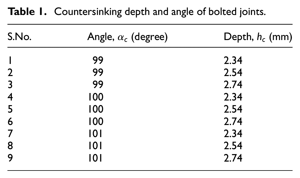
Nine numerical models with designed depth
Countersinking depth and angle of bolted joints.
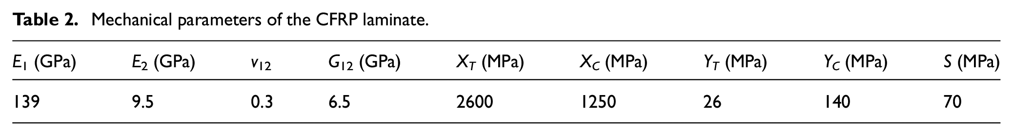
The mechanical parameters of the CFRP laminate are shown in Table 2, 26 and the laminate is composed of carbon-fiber (Toray T700) substrate in (+45°/−45°)7S stacking sequence. Stress analysis combined with failure analysis, and tensile strength prediction are conducted with the numerical model in ABAQUS.
Mechanical parameters of the CFRP laminate.
Materials and validation experiments
In order to validate the numerical model, nine coupons with designed depth
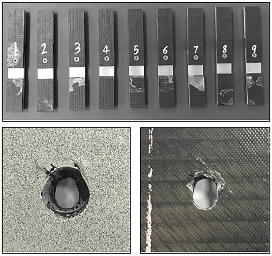
The countersunk bolted CFRP-AL specimens and fractured CFRP coupon 5.
Tensile testing experiments are performed on a 50-kN servo-hydraulic universal material machine (UTM-5504). An ARAMIS high-speed camera with a frame rate from 50 to 80,000 images per second and the strain range from 0.01% to 500% is used for digital image correlation (DIC) and optical deformation measurement (Figure 5). The tensile damage of the CFRP coupon 5 is the typical failure of the CFRP–aluminum single-lap countersunk head bolt joint (Figure 4). The circular hole in the CFRP plate becomes an elliptical hole under the compression of the bolt. Because of the large contact area between the bolt and the CFRP plate, there is no excessive damage on the compressed side. On the other side, there are delaminations and matrix ruptures induced by the bending moment from the head of the countersunk bolts on the CFRP plate which results in the ultimate failure of the joint.
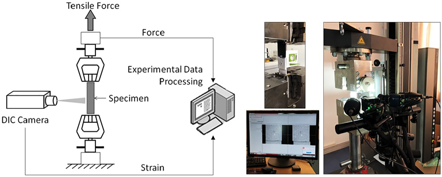
Schematic diagram of the testing and experimental scene.
During the course of the experiments, the stretching machine was loaded at a speed of 0.5 mm/min, and the load–displacement curve was recorded by the DIC camera. FEA and experimental results are shown in Table 3 and Figure 6. The consistency between the experimental data and the FEA results proves the effectiveness of the numerical models of the countersunk bolted joint.
FEA and experimental tensile strengths.
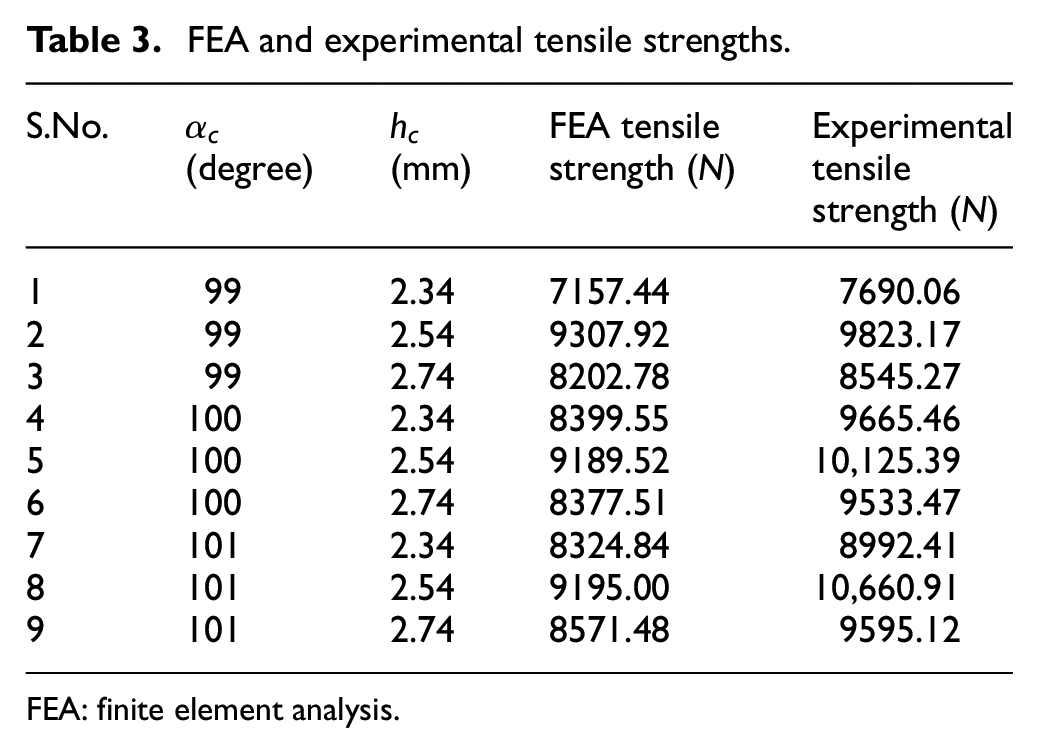
FEA: finite element analysis.
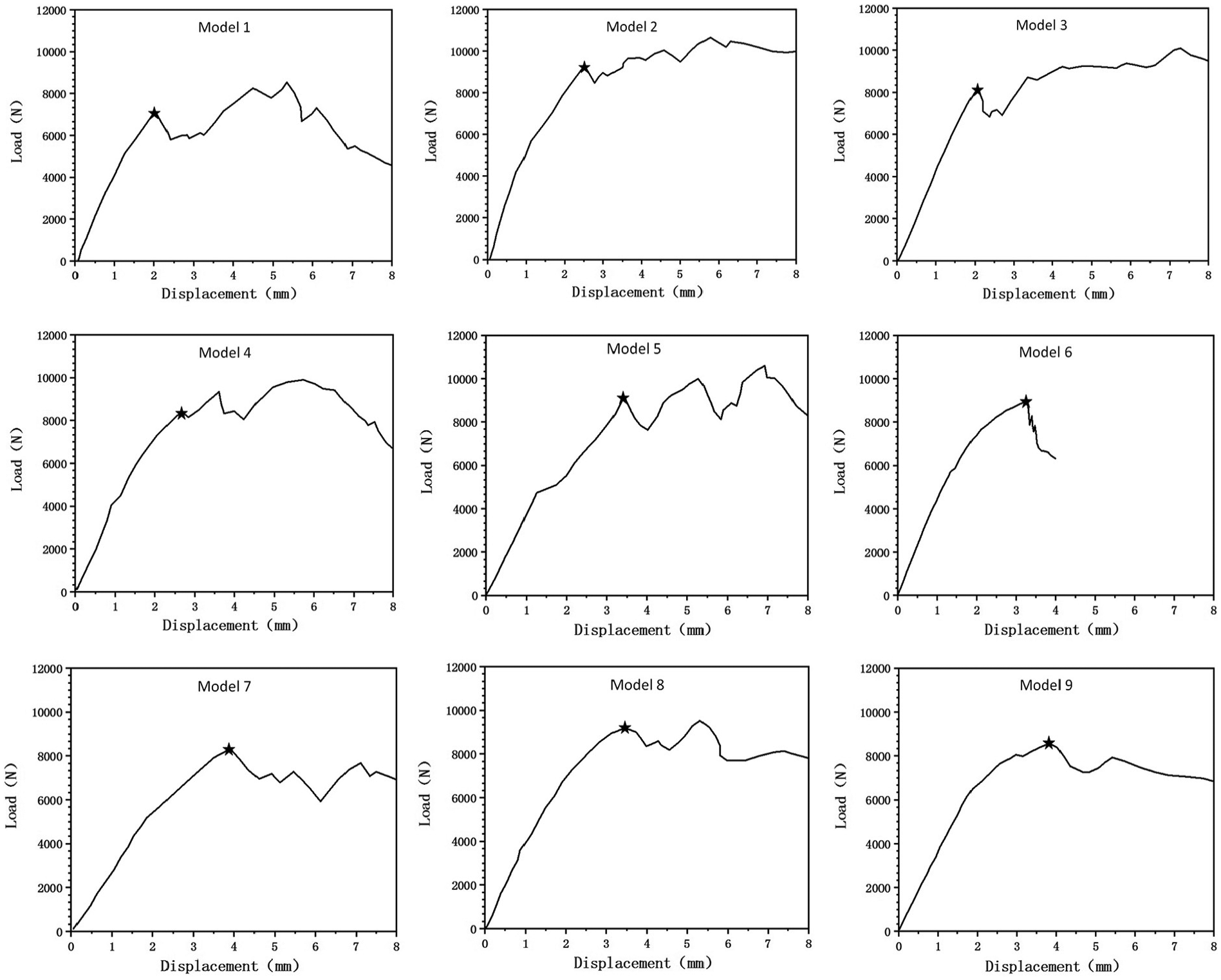
Curves of tensile strength and displacement.
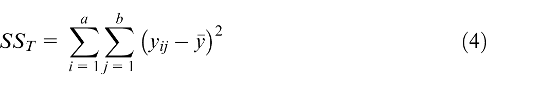
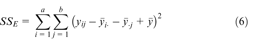
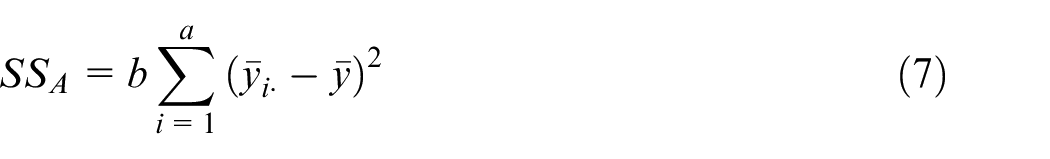
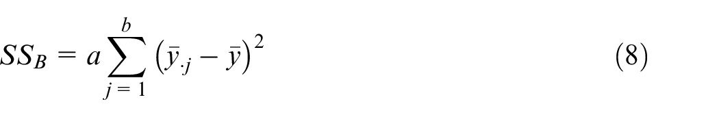
Synergistic effect of hole variation
There is interaction between the depth

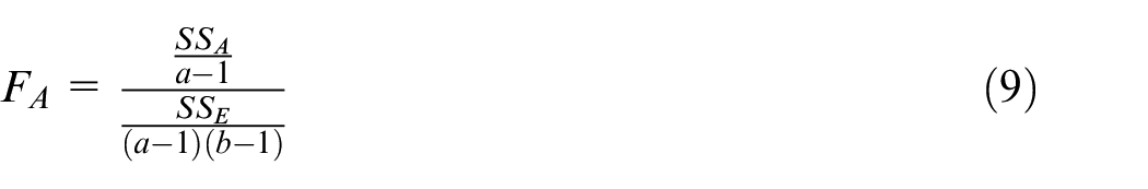
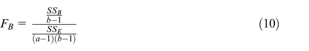
ANOVA of the FEA results.
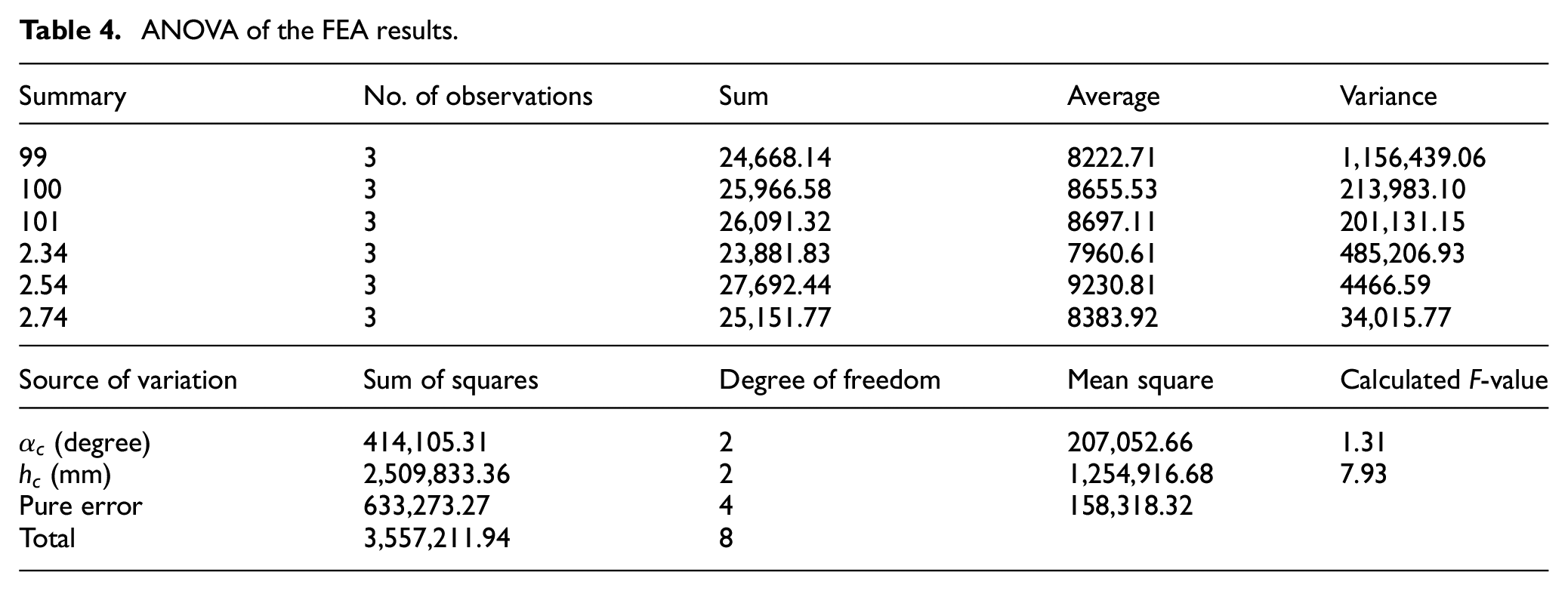
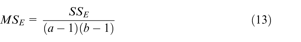
In this case,
Tensile strength and countersunk hole’s depth
Three depths (2.34, 2.54, and 2.74 mm) are applied to the CFRP specimens due to the fabrication precision of the countersinking. Validated FEA model, that is, the phenomenological model, could be used to obtain the tensile strength of the bolted joints with different countersinking depths. Intensive simulations are conducted to investigate the effect between the tensile strength and the depth of the countersunk hole (Table 5).
Tensile strengths of 10 FEA simulations with different depths.
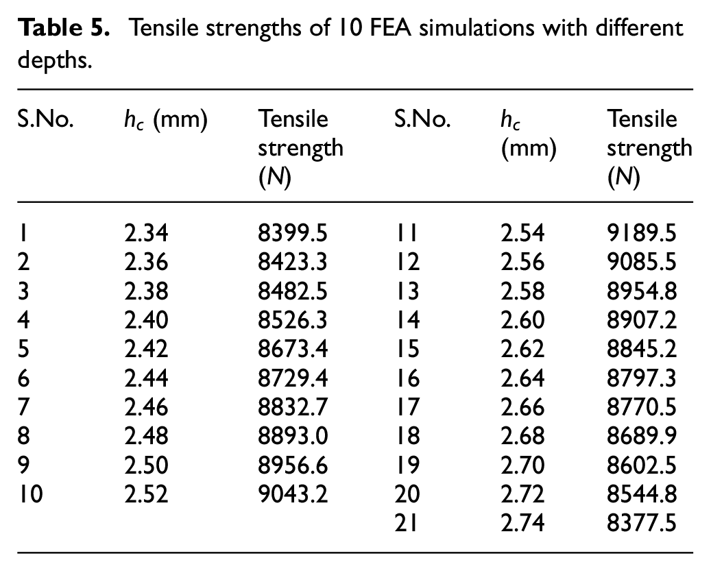
A total of 10 FEA models are constructed with the depths ranging from 2.34 to 2.74 mm, and there are 0.02-mm increments between the depths of the countersunk hole. At the same time, the angle of the countersunk hole is set to 100°.
The relationship between the tensile strength and the depth of the countersunk hole is obtained by the validated numerical models (Figure 7). At nominal depth, the tensile strength is the maximum. When the depth is less than the nominal depth, the bolt head is gradually out of the plate. The tensile load increases the squeezing forces at the head of the bolt. There are heavy stress concentrations around the head of the bolt. Due to the small contacting area between the bolt and the CFRP plate, the CFRP plate is prone to endure delamination than the nominal state (Figure 8). As a result, the tensile strength decreases with the decrease in depth.
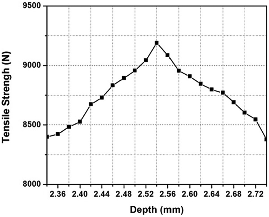
Relationship of tensile strength and countersinking depth.
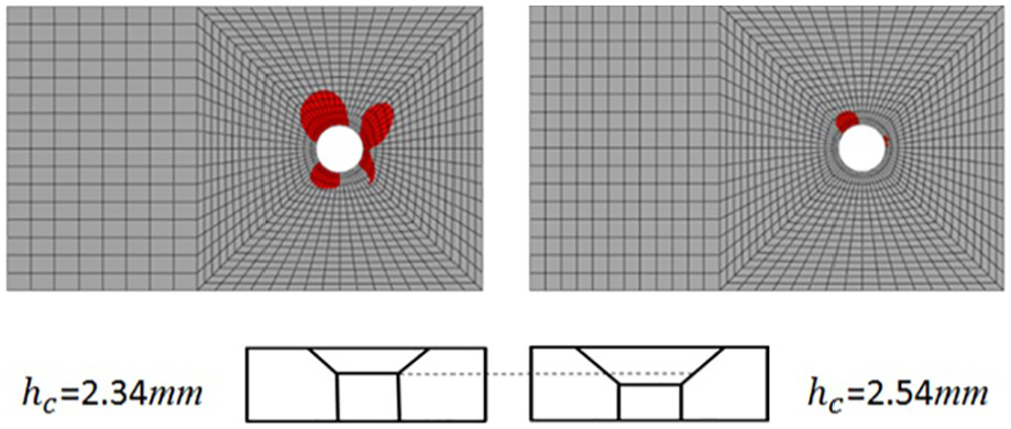
Damage around the bolt’s head with different depths.
When the actual depth is bigger than the nominal depth, the thickness of the composite material below the bolt head portion is continuously reduced. The effective contact area of the CFRP plate and the bolt is continuously reduced. It results in the continuous decrease in the tensile strength of the bolted CFRP plate. The bottom layer of the CFRP plate is most likely to be damaged (Figure 9).
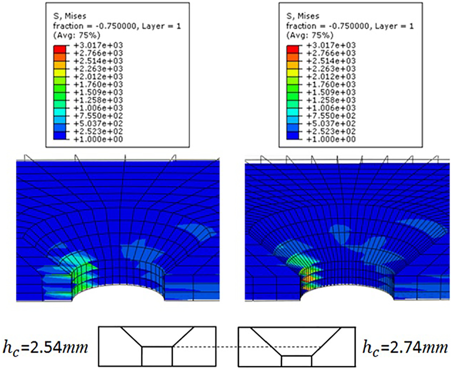
Stress around the hole with different depths.
The relationship could be used to allocate the tolerance of the countersunk holes. The countersunk hole’s depth acceptance criterion, the so-called “tolerance,” could to be decided precisely based on the curve shown in Figure 7. For example, the maximum tensile strength is 9189.5 N when the depth is 2.54 mm. If the tensile strength acceptance is higher than 95%, that is to say, the tensile strength should be higher than 9189.5 × 95% = 8730.0 N, then based on the curve shown in Figure 7, the countersinking depth should be in the range of 2.46–2.66 mm, and tolerance should be
Conclusion
This article proposed a numerical model to investigate the effect of countersinking depth and angle on the tensile strength of the single-bolted countersunk joint. Numerical models were constructed to predict the tensile strengths with designed depths and angles. Nine experimental specimens were fabricated according to the ASTM-D5961 standard, and the experimental results validated the proposed numerical models. ANOVA was used to investigate the synergistic effect of the depth and the angle on the ultimate tensile loading. ANOVA results show that the countersinking depth should be strictly controlled. The relationship between the tensile strength and the depth of the countersunk hole was obtained by the validated numerical models. The relationship provided reference for precision countersinking in the composite bolted joint and could help improving the precision design of the countersunk bolted joint in composites.
Footnotes
Declaration of conflicting interests
The author(s) declared no potential conflicts of interest with respect to the research, authorship, and/or publication of this article.
Funding
The author(s) disclosed receipt of the following financial support for the research, authorship, and/or publication of this article: This project was supported by the National Key Research and Development Program of China (grant nos 2016YFB0101704 and 2016YFB0101700) and National Natural Science Foundation of China (grant no. 51775350).