
Abstract
It is still a challenge to machine high-strength carbon fiber–reinforced polymer with high quality due to its poor machinability. Fiber direction is the critical factor. This article aims to investigate the effects of fiber cutting angle in milling of high-strength unidirectional carbon fiber–reinforced polymer laminates with regard to milling forces, machined surface morphology and surface roughness. The edge trimming and slot milling tests were conducted. The largest radial and tangential forces were observed on 135° fiber cutting angle followed by 90° while the smallest milling forces were observed on 45° fiber cutting angle. Totally, four basic material fracture mechanisms, that is, fiber–matrix debonding, bending-induced fiber fracture, shear-induced fiber fracture and compression-induced fiber fracture, were observed by the analysis of fracture morphology for a single fiber. The four basic material fracture mechanisms dominate the material fracture behavior during the cutting of carbon fiber–reinforced polymer. Besides, it is indicated that surface roughness of the machined surfaces is highly related to the type of the surface defects. Surface cavities caused by fiber–matrix debonding and bending-induced fiber fractures on 45° fiber cutting angle were observed to be the main factors leading to the decline of surface finish in milling of carbon fiber–reinforced polymer laminates.
Keywords
Introduction
High-strength carbon fiber–reinforced polymer (CFRP) has been widely used in aviation industry due to its superior mechanical/physical properties.1–4 However, machining of high-strength CFRP represents the most challenging task as compared to the conventional metals just owing to its superior mechanical/physical properties involved.5–7
Prior to its application, CFRP components are often manufactured in the near-net shape. 8 However, machining operations, such as drilling and milling, are still needed to achieve the final dimensional tolerance and assembly requirement of the CFRP components.
Due to the anisotropic and non-homogeneous material structure, CFRP is significantly different than that of the metals.9–12 Fiber direction is the critical factor affecting the mechanical properties and machining characteristics of CFRP. Up to now, the definitions of the fiber cutting angle and fiber orientation angle in machining of CFRP laminates in the literatures are not yet uniform.8,13–15 In general, fiber orientation angle is defined counterclockwise with respect to the feed direction of the cutting tool (i.e. vf), while the fiber cutting angle is defined counterclockwise with regard to the cutting direction of the cutting edge (i.e. vc). The relationship between fiber orientation angle

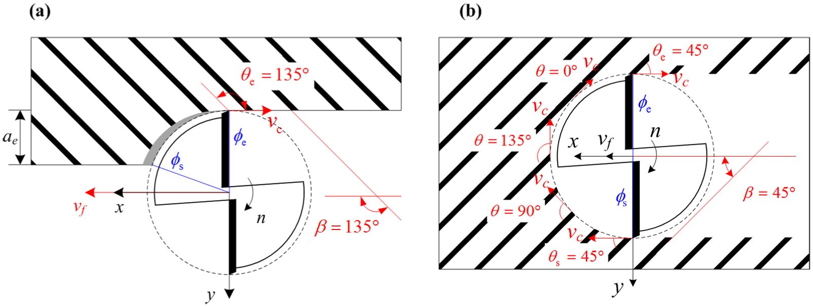
Relationship between fiber orientation angle, fiber cutting angle and tool rotation angle: (a) edge trimming and (b) slot milling.
A majority of studies have focused on drilling of CFRP laminates4,16–23 and CFRP/metal24–30 stacks including drill-induced damages, drill bit geometry and tool wear. However, studies on milling of CFRP laminates are still quite limited.31–33 Hintze et al. 34 investigated the effects of fiber cutting angle on delamination of laminate top layers in slot milling of unidirectional CFRP (UD-CFRP) laminates using double-edged straight flute polycrystalline diamond (PCD) end mills. The experimental results showed that the delaminations occurred only in a certain fiber cutting angle range (90° < θ < 180°) independent of fiber orientation angle. Karpat et al. 8 proposed an instantaneous milling force model considering fiber cutting angle. It was found that the milling force coefficients calculated at 90° < θ < 180° are significantly higher than those calculated at 0° < θ < 90° and the location of maximum tangential force corresponds to the occurrence range of delamination of laminate top layers observed by Hintze et al. Hosokawa et al. 35 carried out side milling (edge trimming) tests of CFRP laminate with high helix end mills. It was indicated that tool wear was considerably dependent on the fiber cutting angle. Relatively large flank wear widths were obtained at fiber cutting angles of 90° and 135°. “Inclination milling” with high helix angle end mill was proposed to control the value of tool vertical cutting force to reduce the surface delamination and fluffing. Haddad et al. 36 investigated the defects generated by different machining processes (including burr tool trimming) and their impact on the mechanical behavior of CFRP. The results showed that the defects generated during the trimming process are fiber pull-out and resin degradation which affected the mechanical behavior of CFRP to some extent.
This work aims to investigate the fiber cutting angle effects in milling of high-strength UD-CFRP laminates. The edge trimming and slot milling tests were conducted. The milling forces, machined surface morphology and surface roughness are obtained, and the results are discussed.
Material and methods
Specimen preparation
T800/X850 UD-CFRP laminates with 6.08 mm thickness (32 plies) were investigated in this study. The laminates were supplied by Commercial Aircraft Corporation of China Ltd (COMAC). The detailed composition and mechanical properties of T800/X850 CFRP are given in Tables 1 and 2, respectively. The laminate was cut into four parts with dimensions of 100 mm × 100 mm. The fibers were deliberately aligned at fiber orientation angle β = 0°, 45°, 90° and 135° to allow milling tests to be conducted on different fiber orientation angles.
Composition of T800/X850 CFRP laminates.
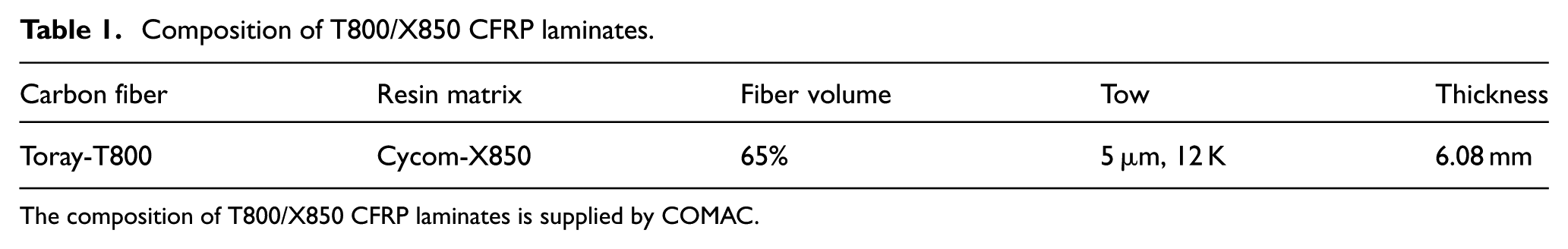
The composition of T800/X850 CFRP laminates is supplied by COMAC.
Mechanical properties of T800/X850 CFRP. 37
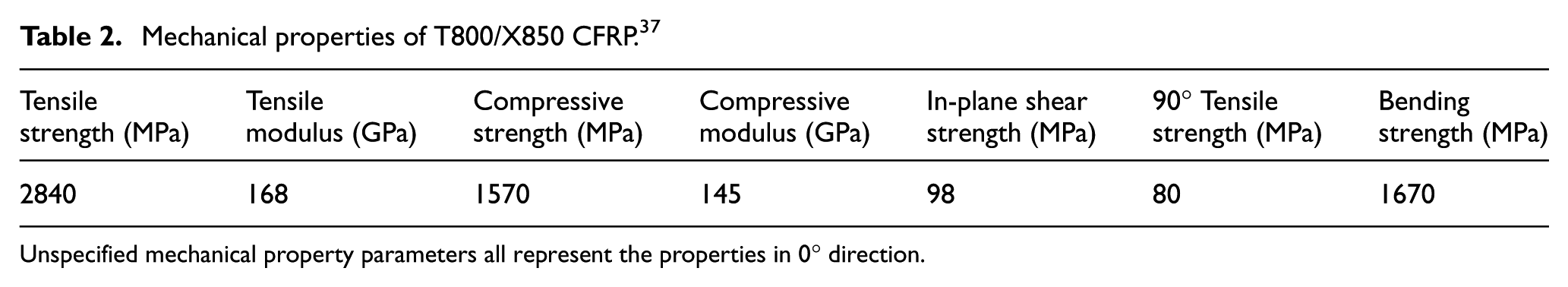
Unspecified mechanical property parameters all represent the properties in 0° direction.
PCD milling tools with 6 mm diameter, two teeth and 0° helix angle were used in the milling tests. The rake angle of the cutting edges is 0° and the clearance angle is 20°. The radius of the cutting edge (rn) is about 5 µm. A helix angle of 0° is employed to keep the cutting edge cutting with a single fiber cutting angle at the same time, which is beneficial to investigate the fiber cutting angle effects. It should be noted that the Vickers hardness of PCD is over 8000 HV according to the tool manufacturer and the Vickers hardness of CFRP is usually 300–500 HV 38 which is significantly smaller than the hardness of PCD. The workpiece and cutting tool used in the milling tests are shown in Figure 2.
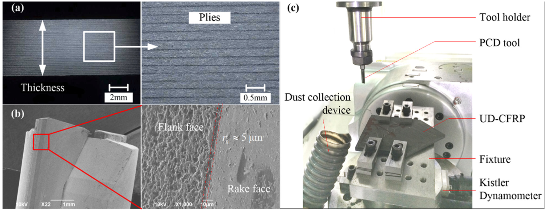
Specimen preparation and experimental setup for the milling tests: (a) UD-CFRP laminate, (b) PCD end mill and (c) experimental setup.
Experimental setup
The milling tests were carried out on Hurco VMX42 three-axis computer numerical control (CNC) vertical machining center with a maximum spindle speed of 12,000 r/min and 0.01 mm positioning accuracy. The experimental setup for the milling tests is shown in Figure 2.
In order to investigate the influence of the fiber cutting angle on the milling forces, machined surface morphology and surface roughness, a radial depth of cut of 0.1 mm was employed (i.e. edge trimming). Slot milling tests were also carried out to obtain the milling forces on a continuum of the fiber cutting angles. The milling test at a given fiber orientation was replicated two times for both the edge trimming tests and slot milling tests. During all the milling tests, no coolant was used. Detailed cutting conditions are listed in Table 3.
Experimental scheme used in the milling tests.
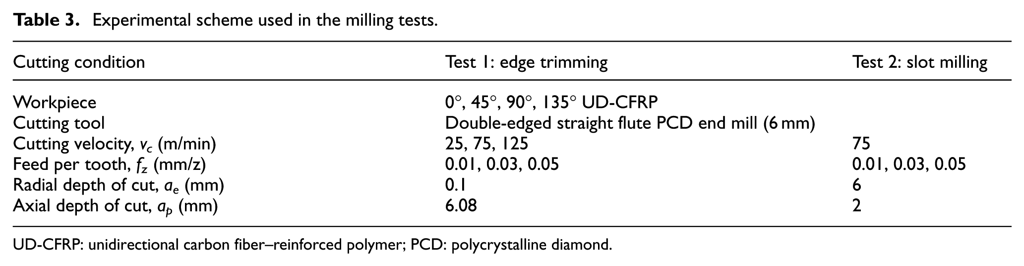
UD-CFRP: unidirectional carbon fiber–reinforced polymer; PCD: polycrystalline diamond.
In terms of measurement devices, a four-component force dynamometer Kistler 9272 combined with a multichannel charge amplifier Kistler 5070A as well as data acquisition system were used to measure and record milling force signals. The milling forces were measured with a sample frequency of 20 kHz to record the force signals in the whole tool rotation period. The surface roughness of the machined surface was measured using a portable profilometer Mitutoyo SJ-210 with a cut-off length of 0.8 mm. The length of measurement is 4.0 mm. The traveling speed of the probe was 0.5 mm/s. In composite machined surface, various surface defects may occur, which affects the values of surface roughness. Therefore, each measurement of surface roughness was replicated six times to ensure sufficient credibility of the obtained results and the average value of the six measurements was used as the final result according to the literature. 21 A digital microscope system Keyence VHX-500FE combined with a scanning electron microscope (SEM) JEOL JSM-6390LV was used to study the morphology of the machined surface.
Results and discussion
Milling forces
Figure 3 gives the milling force measurements in x-, y- and z-directions with respect to the reference system of the dynamometer. As shown in the figure, the milling forces in the vertical direction (Fz) are quite small due to the zero helix angle of the cutting tool in all milling cases. To better understand the relationship between the milling forces and the cutting edge positions, the milling forces are resolved in the tangential and radial directions (Ft, Fr), which can be expressed as equation (2)
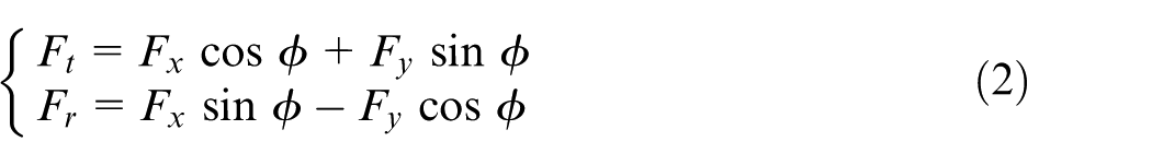
Milling forces measured in (a) edge trimming test and (b) slot milling test.
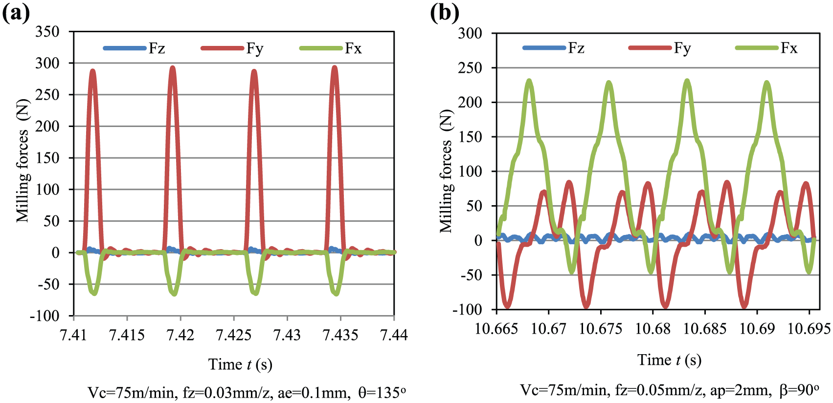
Figure 4 shows the evolution of the tangential and radial forces with respect to the fiber cutting angle for different feed rates and cutting velocities. It was found that the milling forces are critically dependent on the fiber cutting angle. The largest radial force is observed on 135° fiber cutting angle followed by 90° fiber cutting angle while the smallest radial force is obtained when machining 45° fiber orientation laminate. In particular, when edge trimming the CFRP laminate with the cutting parameters of fz = 0.03 mm/z and vc = 75 m/min, the largest radial force 283.5 N is observed on 135° fiber cutting angle followed by 232.8 N for 90° fiber cutting angle; the smallest radial force 87.6 N is obtained when machining 45° fiber orientation laminate. As expected, the milling forces increase with the increase in the feed rate and slightly decrease when increasing the cutting velocity, which is consistent with the result obtained by An et al., 37 Karpat et al. 8 and Zaghbani et al. 39 Besides, it is noted that the error range of the radial and tangential forces for 45° fiber cutting angle is 14% and 41%, respectively, which are considerably higher than the values of below 5% for other fiber cutting angles.
Tangential and radial forces in edge trimming tests for different (a) feed rate and (b) cutting velocity.
Figure 5 shows the tangential and radial forces as a function of tool rotation angle and fiber cutting angle recorded in the slot milling tests. The peak values of the radial force and tangential force measured on 45° and 90° are found to be larger than those measured on 0° and 135° fiber orientation angle. It is interesting to note that a sudden decrease in the radial and tangential forces was observed near the 45° fiber cutting angle independent of the fiber orientation angle (except for 45° fiber orientation angle; 45° fiber cutting angle corresponds to the starting or ending point of the milling process). On the contrary, the largest radial and tangential forces are also consistently observed near 135° fiber cutting angle (except for 135° fiber orientation angle; 135° fiber cutting angle corresponds to the starting or ending point of the milling process). The relationship of the milling force values for different fiber cutting angles derived in the edge trimming tests is consistent with the relationship of the milling force values derived in the slot milling tests.
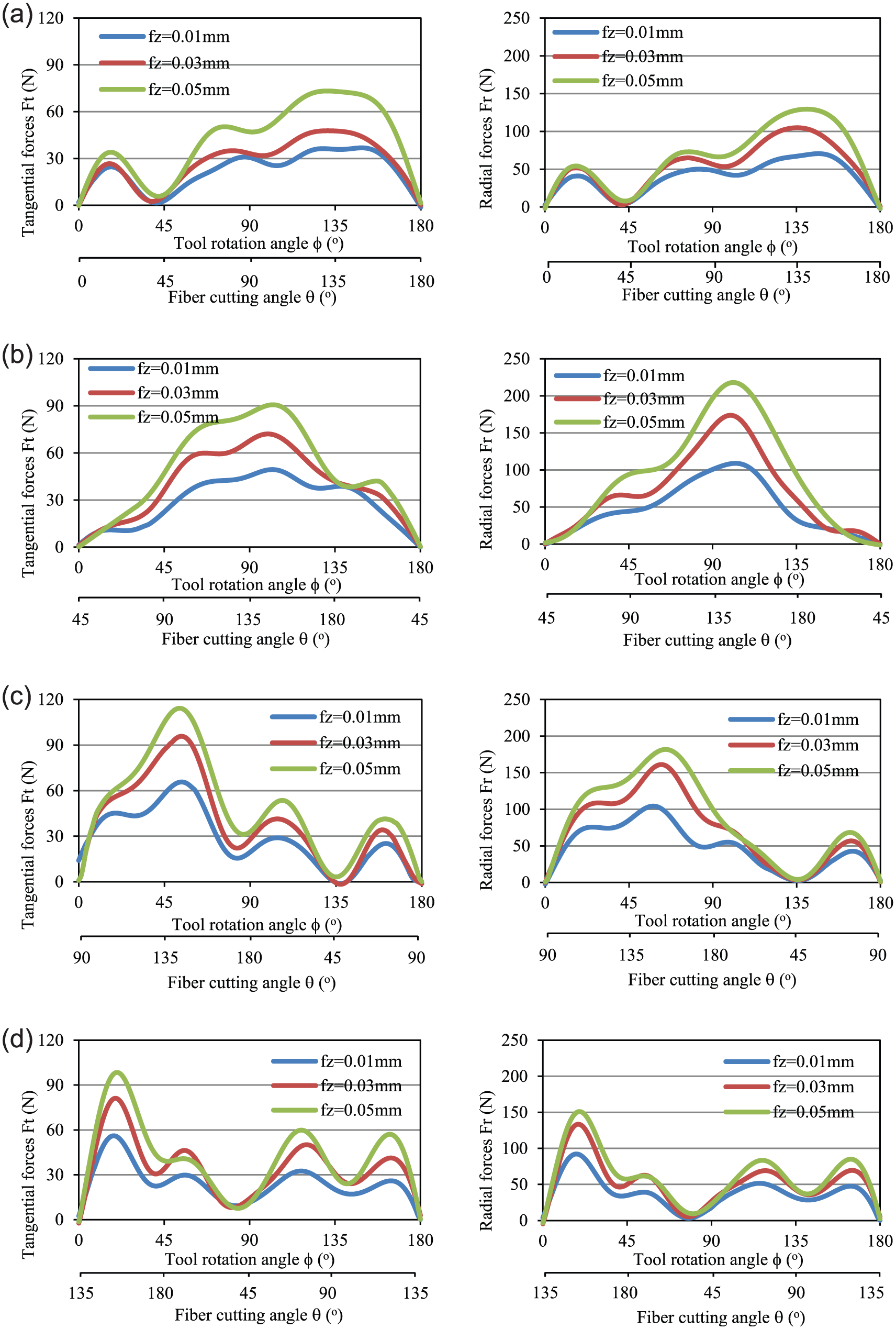
Tangential and radial forces in slot milling tests for (a) β = 0°, (b) β = 45°, (c) β = 90° and (d) β = 135°.
Furthermore, the average milling force in the fiber cutting angle range of 0° < θ < 90° is significantly smaller than that in the fiber cutting angle range of 90° < θ < 180°. Taking 90° fiber orientation angle as an example, the average radial and tangential forces in the fiber cutting angle range of 0° < θ < 90° are 41.6 and 29.6 N, respectively, while the average milling force in the fiber cutting angle range of 90° < θ < 180° is 128.0 and 68.5 N, respectively. The increase is 208% and 131%, respectively. It is meaningful to the edge trimming of the CFRP laminates. To obtain small average milling forces, up milling of 0° fiber orientation and down milling of 90° fiber orientation are recommendable.
Material fracture mechanisms based on fracture analysis
Depending on the fiber cutting angle, the material removal mechanism has great difference during the cutting of UD-CFRP laminates. The material fracture mechanisms are observed to be guided primarily by the fracture of fibers and the fiber–matrix debonding. Different from the ductile metal materials, the fracturing of the carbon fibers occurs with almost no plastic deformation. In the machined surface of the UD-CFRP laminates, totally four basic material fracture mechanisms, that is, fiber–matrix debonding, bending-induced fiber fracture, shear-induced fiber fracture and compression-induced fiber fracture, were observed by the analysis of fracture morphology for a single fiber, as shown in Figure 6. Typical bending-induced fiber fractures and shear-induced fiber fractures are observed on 45° fiber cutting angle and 135° fiber cutting angle, respectively. The fracture morphologies are consistent with those obtained by Da Silva and Johnson 40 in their flexural and tensile failure tests of single carbon fibers. Typical compression-induced fiber fractures are observed at the fiber cutting angle 90°. The fracture morphologies are consistent with those obtained by Hawthorne and Teghtsoonian 41 in their compression failure tests of CFRP laminates. The shear-induced fiber fractures are smooth while rough surfaces are observed in the fiber fracture morphologies caused by compression-induced fiber fractures which can be attributed to the plowing action of the cutting edges. The four basic material fracture mechanisms dominate the material fracture behavior during the cutting of CFRP.
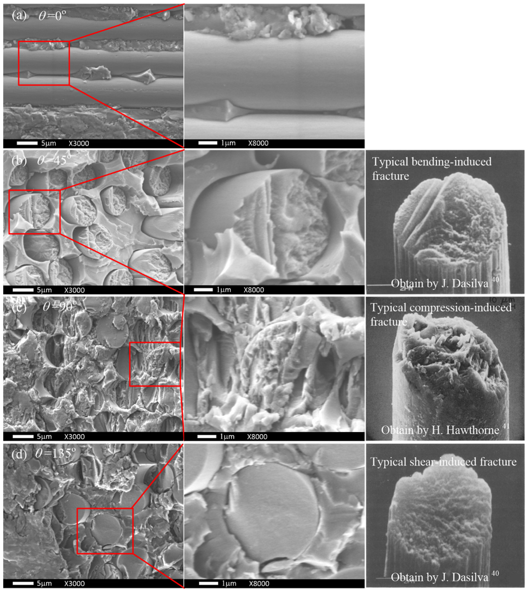
Typical fiber (matrix) fracture type in the milling of UD-CFRP: (a) fiber–matrix debonding, (b) bending-induced fiber fracture, (c) compression-induced fiber fracture and (d) shear-induced fiber fracture.
Typical surface morphologies and machined surface defects
The reliability of the machined components, especially of high-strength applications, is critically dependent on the quality of the surfaces produced by machining. In the machining of CFRP, various machining defects may occur including fiber pull-out, fiber breakage, fiber–matrix debonding, matrix loss as well as delamination of the top or bottom ply of the laminate structure. Different fiber cutting angles correspond to different surface morphologies and machining defects caused by the different material removal mechanisms. Figure 7 shows the SEM photographs of the machined surfaces for different fiber cutting angles obtained in the edge trimming tests.
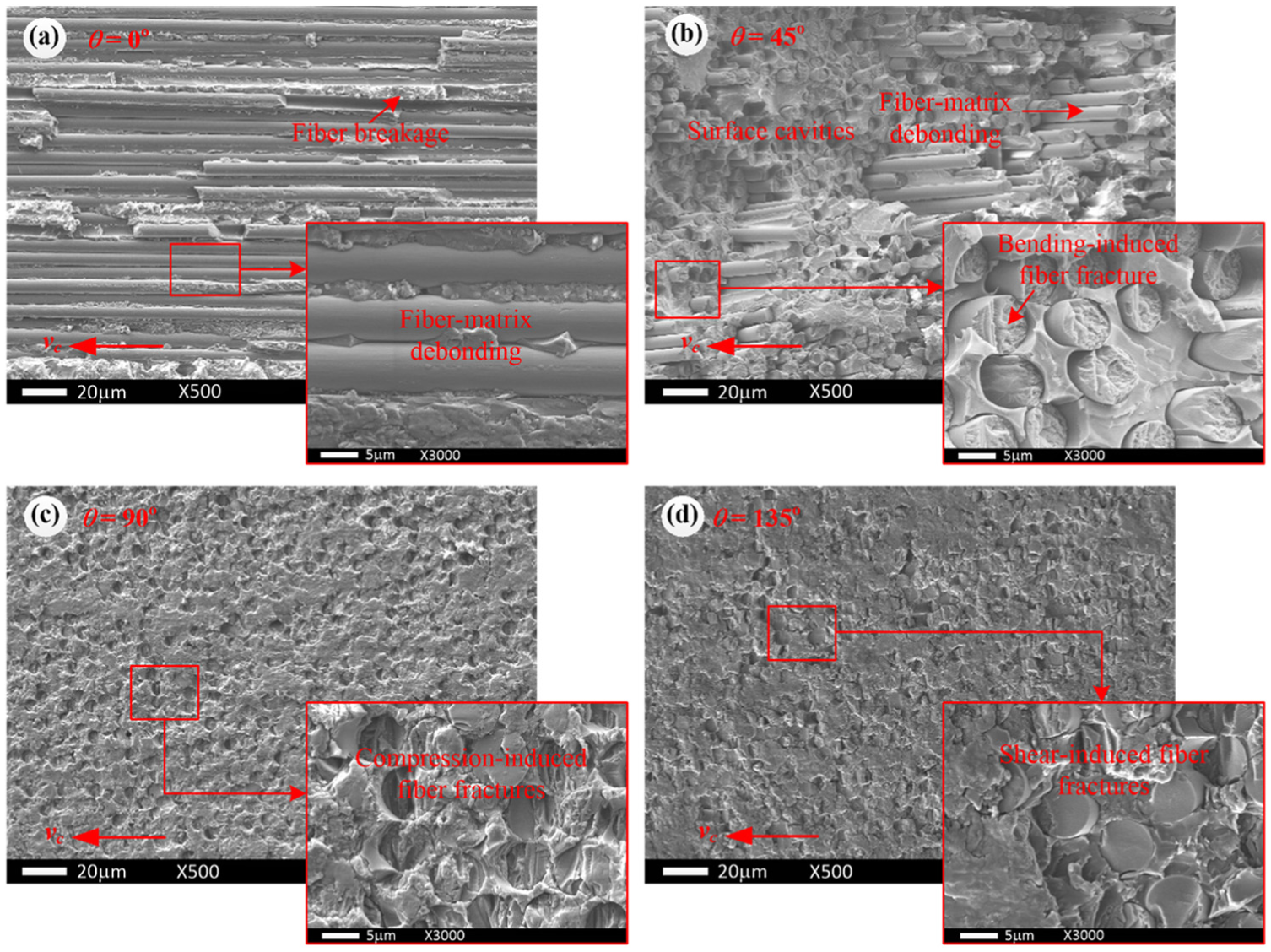
Typical machined surface morphologies in the edge trimming tests: (a) θ = 0°, (b) θ = 45°, (c) θ = 90° and (d) θ = 135°.
As shown in Figure 7, the material removal mechanisms when machining 0° fiber orientation laminate were mainly fiber–matrix debonding and fiber breakages (caused by compression-induced fiber fractures). The material removal mechanisms when machining 45° fiber orientation laminate were mainly fiber–matrix debonding followed by the bending-induced fiber fractures. Since the fracture position (bending-induced fiber fractures) is lower than the cutting plane, surface cavities in the machined surface were formed and the machined surface appeared as saw-tooth morphology, as shown in Figure 8. The fiber–matrix debonding plays a significant role in the material removal mechanisms for 0° and 45° fiber cutting angles. The difference is the propagation direction is parallel to the cutting direction when machining 0° fiber orientation laminate, so there are almost no sub-surface damages occurring in the machined surface. The material removal mechanisms when machining 90° and 135° fiber orientation laminates were mainly compression-induced fiber fractures and shear-induced fiber fractures, respectively. Without the fiber–matrix debonding, there are almost no sub-surface damages observed in the machined surfaces. Therefore, the machined surface morphologies for different fiber cutting angles are highly correlated to the material removal mechanisms. Based on the fracture analysis shown in Figures 6 and 7, different material fracture mechanisms were obtained for different fiber cutting angles. They are schematically summarized in Figure 9.
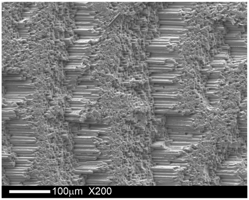
Typical saw-tooth surface morphology for θ = 45° caused by fiber–matrix debonding followed by bending-induced fiber fractures.
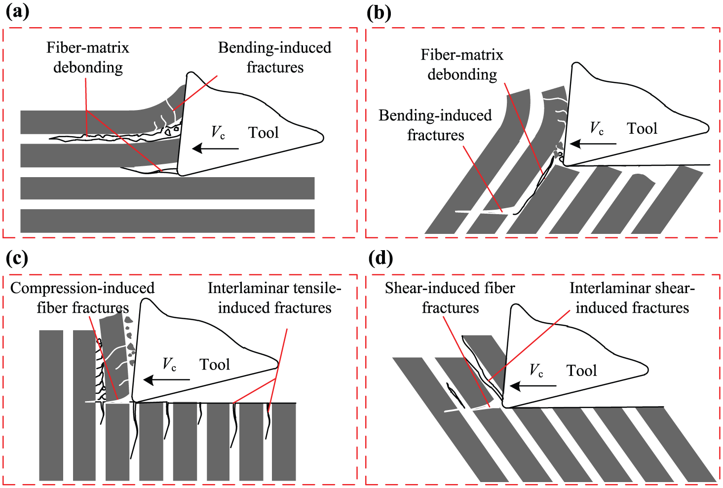
Schematic diagrams illustrating material fracture mechanism of CFRP for different fiber cutting angles (a) sita = 0°,(b) sita = 45°, (c) sita = 90° and (d) sita = 135°.
As listed in Table 2, in-plane shear strength (98 MPa) and 90° tensile strength (80 MPa) of CFRP are far smaller than tensile strength (2840 MPa) or compressive strength (1570 MPa). Obviously, fiber–matrix debonding is correlated to in-plane shear strength and 90° tensile strength. Shear-induced fiber fractures and compression-induced fiber fractures are correlated to tensile strength and compressive strength. Based on this fact, fiber–matrix debonding is much easier to take place than shear-induced fiber fractures and compression-induced fiber fractures. However, the fiber–matrix debonding plays a significant role in the material removal mechanisms for 0° and 45° fiber cutting angles, while there was almost no fiber–matrix debonding occurring for 90° and 135° fiber cutting angles. Therefore, the milling forces of 90° and 135° fiber cutting angles are significantly higher than those of 0° and 45° fiber cutting angles. Compared to the cutting of 90° fiber cutting angle laminates, when cutting 135° fiber cutting angle laminates, the fiber shear fracture plane is parallel to the cutting direction (although part of the fibers’ fractures occur perpendicular to the fiber direction induced by compression), that is, the shear area of 135° is larger than that of 90°. Therefore, the cutting of 135° fiber cutting angle laminates will consume more energy than the cutting of 90°, and hence the milling forces were evaluated.
In particular, under the 90° interlaminar tensile stresses, interlayer separation occurs and sub-surface cracks will be generated on the machined surface. That situation usually occurs at the beginning of the milling process due to the support loss of the edge plies. As shown in Figure 10, the cracks are covered with the machined surface at the initial stage of the milling process which leads to the decline of the machined surface integrity.
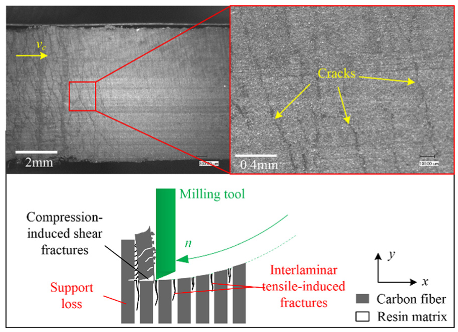
Macroscopic morphology and schematic diagrams illustrating cracks’ forming mechanism of the machined surface at beginning stage in down milling of 90° fiber orientation CFRP laminate.
Surface roughness of the machined surfaces
The evaluation profiles of the machined surfaces under different fiber cutting angles obtained in the edge trimming tests are presented in Figure 11. Based on the analysis of the machined surface morphology and machined defects above, it was revealed that the surface roughness is highly relevant to the types of the defects on the machined surfaces. It was indicated that the evaluation profile of 45° fluctuates severely. Periodic oscillation of the evaluation profile reveals that the surface is rough, which can be contributed to the wavy morphology and a large number of cavities on the machined surface. The evaluation profile of 135° is the most flat and the surface roughness is the smallest.
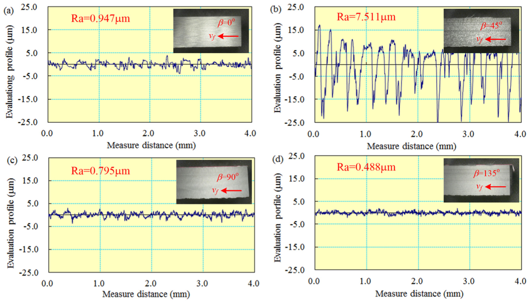
Evaluation profiles and macroscopic morphologies of the machined surfaces for the fiber cutting angle of (a) θ = 0°, (b) θ = 45°, (c) θ = 90° and (d) θ = 135°.
Radar maps were plotted to show the fiber cutting angle effects on the surface roughness as shown in Figure 12. It is indicated that the surface roughness Ra is highly dependent on the fiber cutting angle due to its significant effect on the machined surface morphology. It is indicated that surface roughness Ra reaches maximum when θ = 45°. Except for 45°, the variation in the surface roughness value is very small. For θ = 45°, the value of Ra is 7–10 times higher than those for θ = 0°, 90° and 135°. It is clear that the surface roughness Ra curves are flat with a small variation except for 45° fiber cutting angle in which the cutting velocity direction of the cutting edge is against the fiber direction.
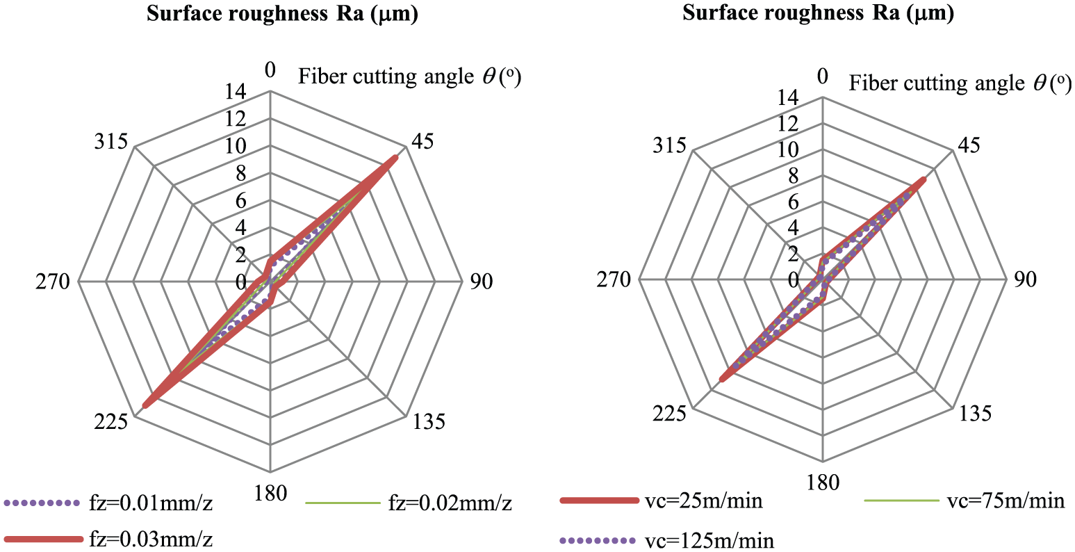
Feed rate and cutting velocity effects on the machined surface roughness Ra: (a) feed rate effect and (b) cutting velocity effect.
Comparison of machined surface quality with and without 45° fiber orientation plies
In order to better understand the influence of the 45° fiber orientation ply on the machined surface quality, milling tests of multidirectional CFRP laminates with and without 45° fiber orientation plies were performed. The machined surface morphologies and the values of surface roughness Ra were obtained. The measurements of surface roughness were taken perpendicular to the feed direction since the fiber orientations of plies have a significant influence on the measured roughness values of the machined surface. The experimental results are presented in Figure 13. Long and deep cavities are observed only on the machined surface of the 45° fiber cutting angle. Correspondingly, sudden decreases appear in the evaluation profile of the machined surface due to the presence of the surface cavities. The surface roughness (Ra = 4.546 µm) for the machined surface with 45° fiber orientation is significantly higher than that (Ra = 2.344 µm) for the machined surface without 45° fiber orientation. Therefore, it is indicated that surface cavities (caused by interlaminar separation and fiber–matrix pull-outs) existing in the machined surface of 45° fiber cutting angle are the main factor leading to the decline of the surface roughness in milling of CFRP laminates.
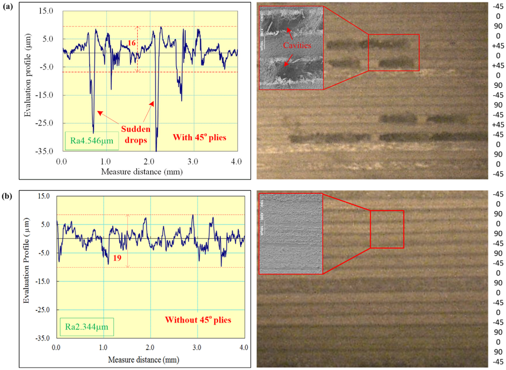
Typical surface morphologies and evaluation profiles during milling of the multidirectional CFRP laminate: (a) with 45° plies and (b) without 45° plies.
Conclusion
This work concerns the influence of the fiber cutting angle on milling forces, machined surface morphology and surface roughness during milling of T800/X850 high-strength UD-CFRP laminates. The edge trimming tests and slot milling tests were conducted. The results can be summarized as follows.
In the edge trimming tests, the largest radial and tangential forces were observed on 135° fiber cutting angle while the smallest milling forces were observed on 45° fiber cutting angle. In slot milling tests, sudden decreases in radial and tangential force curves were observed near the 45° fiber cutting angle independent of the fiber orientation angle while the peak values of the milling forces were observed on 135° fiber cutting angle, which was consistent with the results obtained in the edge trimming tests.
In the machined surface of the UD-CFRP laminates, totally four basic material fracture mechanisms, that is, fiber–matrix debonding, bending-induced fiber fracture, shear-induced fiber fracture and compression-induced fiber fracture, were observed by the analysis of fracture morphology for a single fiber. The four basic material fracture mechanisms dominate the material fracture behavior during the cutting of CFRP.
It was indicated that surface cavities (caused by fiber–matrix debonding and bending-induced fiber fractures) existing in the machined surface of 45° fiber cutting angle were the main factors leading to the decline of surface finish in milling of CFRP laminates.
Footnotes
Declaration of conflicting interests
The author(s) declared no potential conflicts of interest with respect to the research, authorship and/or publication of this article.
Funding
The author(s) disclosed receipt of the following financial support for the research, authorship, and/or publication of this article: This work was supported by the Important National Science & Technology Specific Projects (2016ZX04002005) and National Natural Science Foundation of China (No. 51475298) for funding this research.