
Abstract
The chord error employed in computer-aided manufacturing and computer numerical control systems is a crucial index to evaluate the machining accuracy of machined parts. It is usually estimated by the second-order method, that is, the osculating circle method. The second-order estimation only takes the curvature of the curve into account, which will bring about great estimation error when applying to freeform curves. In this article, a third-order method that estimates the chord error using conical helices is proposed. By investigating the geometric properties of the conical helix, it is found that there exists a conical helix that has third-order contact with the freeform curve. With the aid of this conical helix, a third-order model for estimating the chord error of freeform curves is developed. Numerical examples of three freeform curves are provided to verify the effectiveness of the proposed estimation model.
Keywords
Introduction
Toolpath generation is the core technology for numerical control machining and plays an important role in guaranteeing machining accuracy and efficiency. 1 It can be mainly classified into four categories: iso-parameter machining,2–4 iso-plane machining,5,6 iso-scallop machining7–9 and constant chord error machining. 10 An essential step in all the four methods is to calculate the step length, which is generally determined by the chord error. Since the chord error describes the deviation of the actual machining surface from the desired nominal surface, it is important to calculate the chord error accurately.
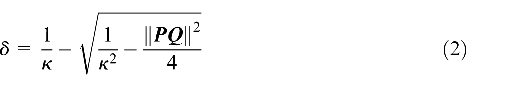
Chord error is defined as the Hausdorff distance between the desired toolpath and the generated toolpath. As shown in Figure 1(a), arc

where
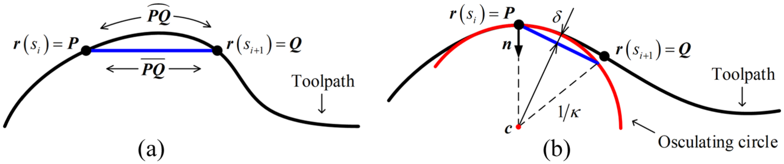
Chord error: (a) definition of chord error and (b) osculating circle estimation.
Since the osculating circle estimation has a closed-form solution, it is widely used not only in computer-aided manufacturing (CAM) system but also in computer numerical control (CNC) system. Yong and Narayanaswami 14 and Li et al. 15 applied the osculating circle estimation to check the chord error constraint at current interpolation point. Tikhon et al. 16 and Karimi and Nategh 17 adopted the osculating circle estimation to determine the maximum kinematic error permitted by the chord error tolerance. To avoid feedrate fluctuation, Lee et al. 18 and Zhao et al. 19 proposed a method to generate a jerk-limited feedrate profile. Huang and Zhu 20 extended this idea to generate a jerk-continuous feedrate profile with trigonometric function. In these works, the osculating circle estimation is used twice: (1) identify critical points and (2) calculate nominal feedrates at critical points. In addition, Sun et al.21–23 proposed several interpolation algorithms for five-axis machining, which also applied the osculating circle estimation to calculate nominal feedrates. Although the osculating circle estimation has attained extensive applications, it can result in significant estimation errors for freeform curves of which the curvatures are variable and the torsions are not zero. It can be seen from Figure 1 that for planar curves, the chord error is affected by curvature variation. For spatial curves, it is also affected by the torsion. To account for the curvature variation and torsion, a high-precision chord error estimation method using third-order approximation is proposed in this work.
The remainder of this article is organized as follows. In section “Third-order approximation of freeform curve,” the geometric properties of the conical helix are investigated, and it is proved that a freeform curve can be locally third-order approximated by a conical helix. In section “Third-order chord error estimation,” a novel third-order method for calculating chord error of freeform curve is proposed. Numerical results are given in section “Numerical examples,” and conclusions are drawn in section “Conclusion.”
Third-order approximation of freeform curve
The osculating circle method uses the osculating circle to locally approximate the freeform curve, which only takes the curvature into account. Analogously, here a conical helix is used to locally approximate the freeform curve by considering the influences of the torsion and the curvature variation.
Representation of conical helix
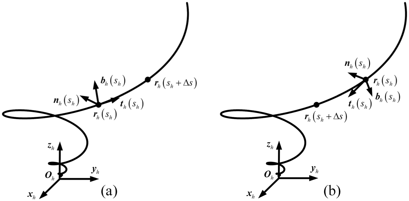
As shown in Figure 2(a), in coordinate frame
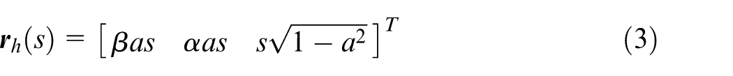
where auxiliary parameters
Two conical helices: (a) curvature variation is negative and (b) curvature variation is positive.
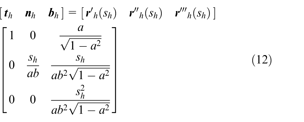
For any point on the conical helix, there exists a three-dimensional (3D) Frenet frame attached to it with unit tangent vector
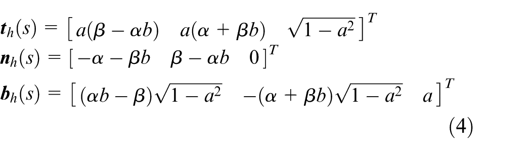
For notation simplicity,
where
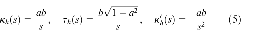
Since the curvature of the freeform curve is an absolute value, it can be inferred from equation (5) that parameter b is always positive. Then, the curvature variation of the conical helix defined by equation (3) is always negative, that is,
where
Third-order approximation of freeform curve
In this section, the conical helix which has third-order contact with the freeform curve is derived.
In differential geometry, contact order is introduced to evaluate the approximation of two contact curves around the contact point.
24
Two curves
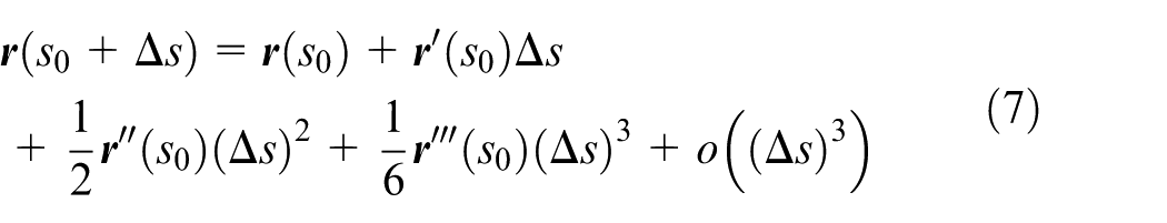
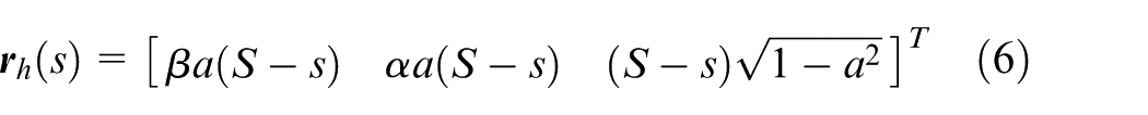
The first- to the third-order derivatives of the freeform curve
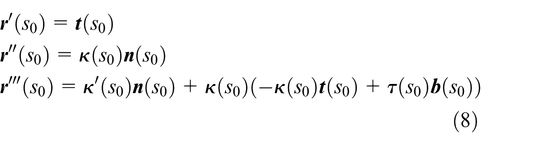
where
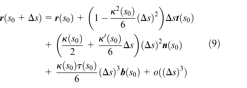
According to the contact order definition and equation (9), if the torsion and the curvature variation are taken into account in locally approximating the freeform curve, the approximating curve has at least third-order contact with the freeform curve. For the third-order approximation, we have the following theorem.
Theorem 1
If the curvature
Proof
Suppose there is a conical helix

Then,
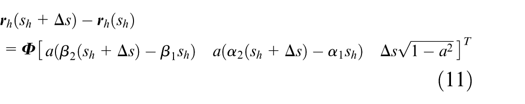
where
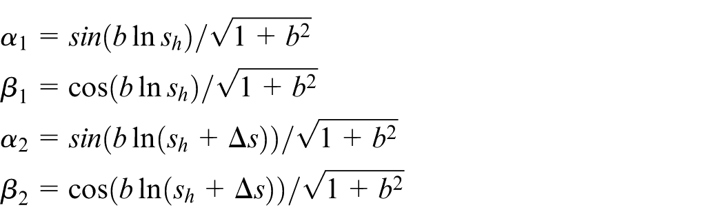
From equations (4) and (5), we get
Then, we need to prove the following equations according to equations (11) and (12)
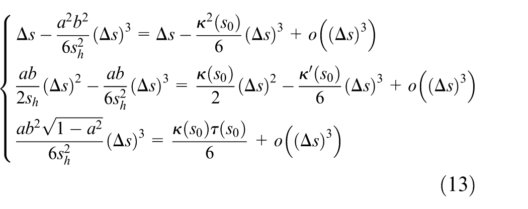
Note that equation (13) holds if we have the following equations
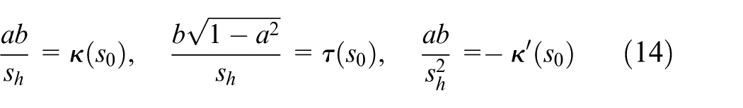
By combining equations (5) and (14), the parameters a and b of the helix conical and the helix parameter
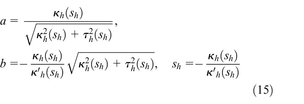
Therefore, the freeform curve
If the curvature variation of the freeform curve satisfies
The freeform curve in Khalick’s work 26 is taken as an example to illustrate the difference between the second- and third-order approximations. As can be seen in Figure 3, the conical helix that has third-order contact with the freeform curve is closer to the freeform curve than the osculating circle. Therefore, the proposed third-order approximation can attain a more accurate result in estimating the chord error.
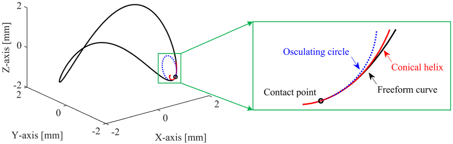
Comparison between second-order contact and third-order contact around the contact point.
Third-order chord error estimation
Since any freeform curve can be locally third-order approximated by a conical helix according to Theorem 1, the chord error of the freeform curve can be estimated by the chord error of a conical helix.
As shown in Figure 4,


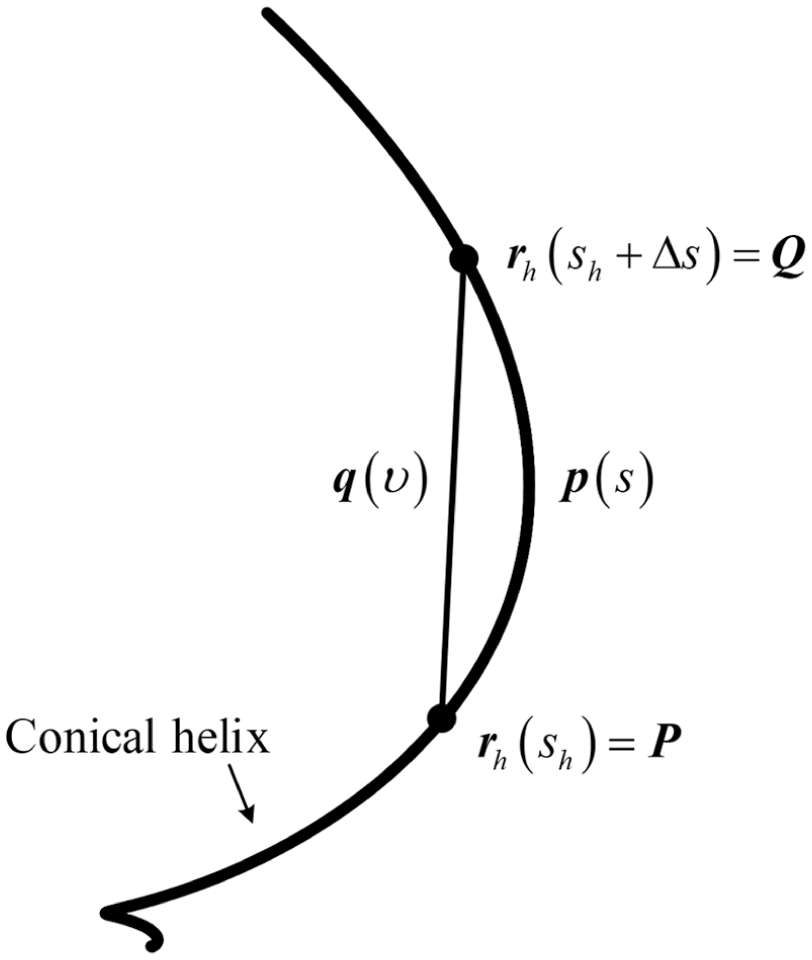
Chord error of conical helix.
According to equation (1), for a point

Solving equation (18) for parameter
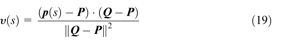
Substituting equation (19) into equation (17) yields

where
Then, the chord error
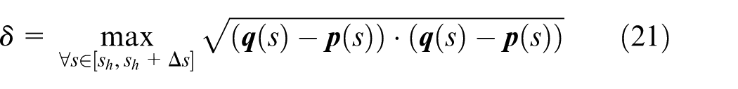
Letting
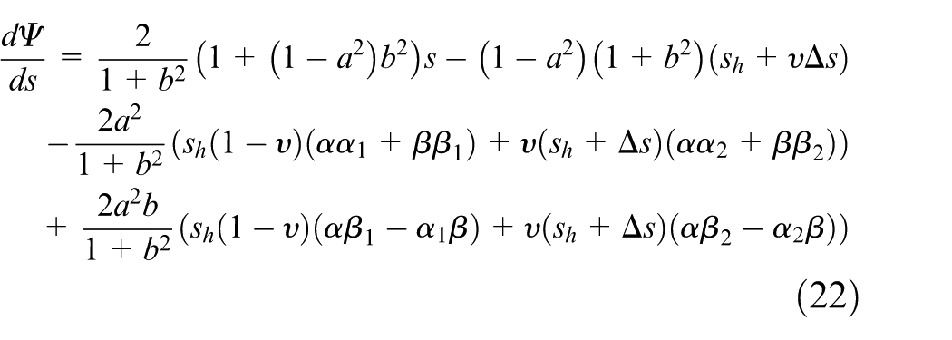
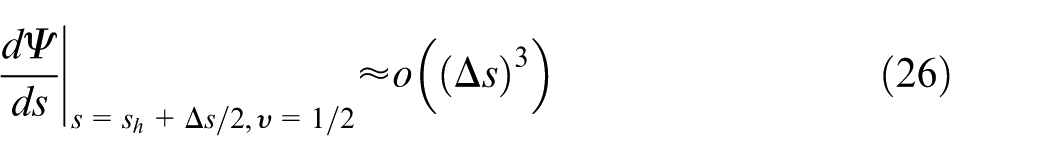
In the following, using Taylor expansion, we will prove that the chord error is attained when
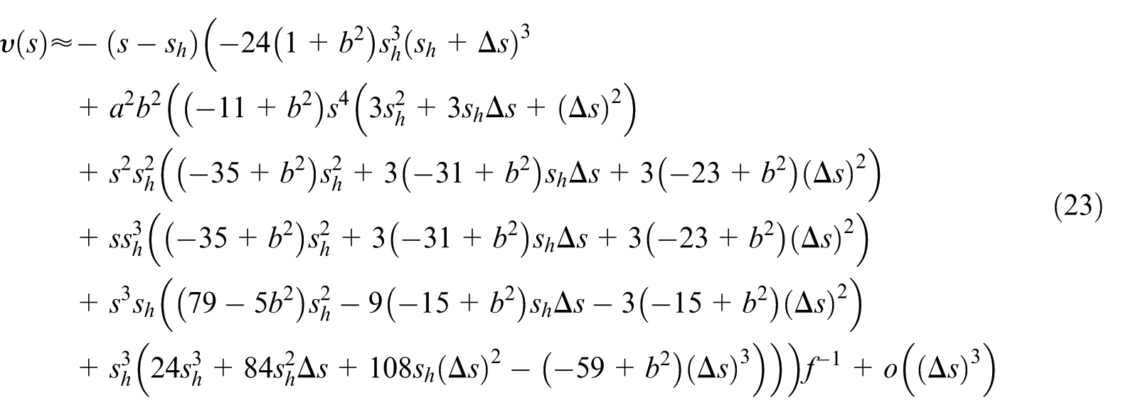
where
And
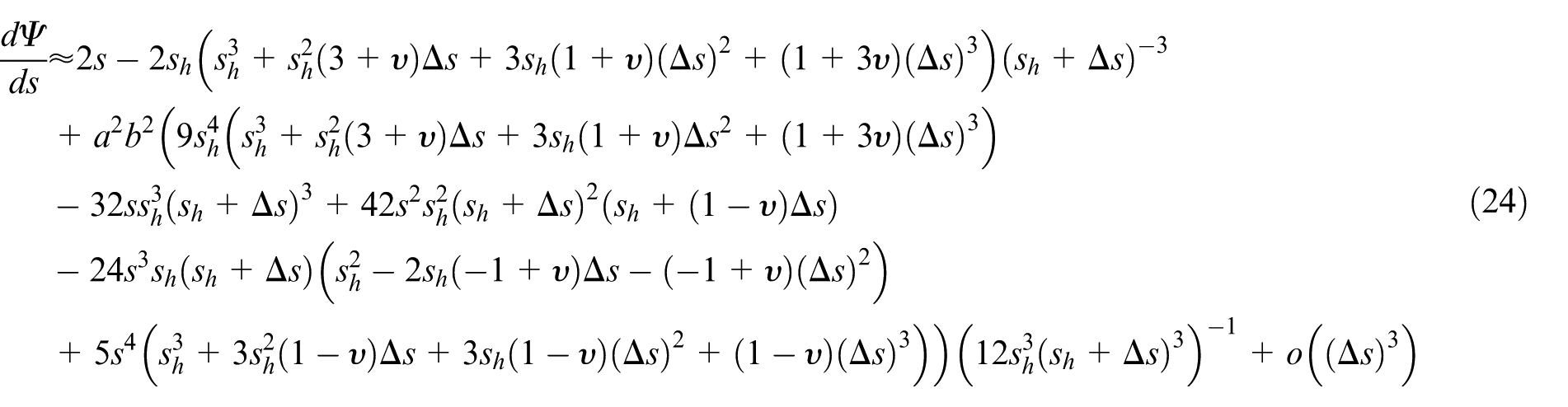
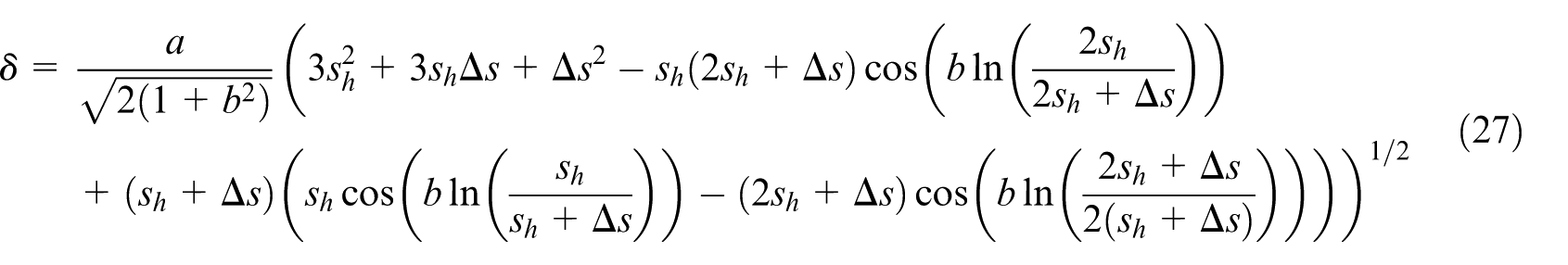
Let
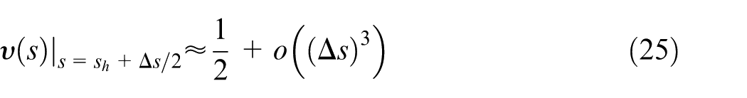
Since the chord error in CAM and CNC systems usually falls between the millimeter and micron scale, equation (25) can be simplifies as
which can be simplifies as
To analytically calculate the chord error, we should know the arc length increment

By the third-order Taylor expansion of cosine and natural logarithmic functions, we have
According to equation (29),
It should be noticed that the additional computational burden using the third-order approach instead of the second-order approach mainly comes from the calculation of the third-order derivative of the freeform curve. Take a quartic non-uniform rational basis spline (NURBS) curve for example. The number of arithmetic operations introduced by the third-order derivative are 4 for addition, 13 for subtraction, 23 for multiplication and 3 for division. Hence, the increased computation will not deteriorate the real time performance.
Numerical examples
In the numerical examples, the freeform curves are first split into a series of cutter location points with a specified chord error constraint. As a result, the real chord error for each segment determined by two adjacent cutter location points is identical to the specified value. The estimated chord errors at each cutter location point are obtained through two steps: (1) approximate the freeform curve with osculating circles and conical helices and (2) estimate the chord error with a chord length equal to the corresponding segment length. As can be seen, the same cutter location point and same chord length are used for the two methods.
Example 1
In this section, a planar butterfly curve in Figure 5(a) is split into 509, 361, 292 and 253 cutter location points under the chord error constraints, that is, of 0.005, 0.01, 0.015 and 0.02 mm, respectively. The curvature of the butterfly curve is plotted in Figure 5(b). Compared with the osculating circle method, the proposed method significantly improves the estimation accuracy, as can be seen from Figures 6 and 7. The maximum improvement of estimation accuracy with the proposed method is 87.29% when the chord error constraint
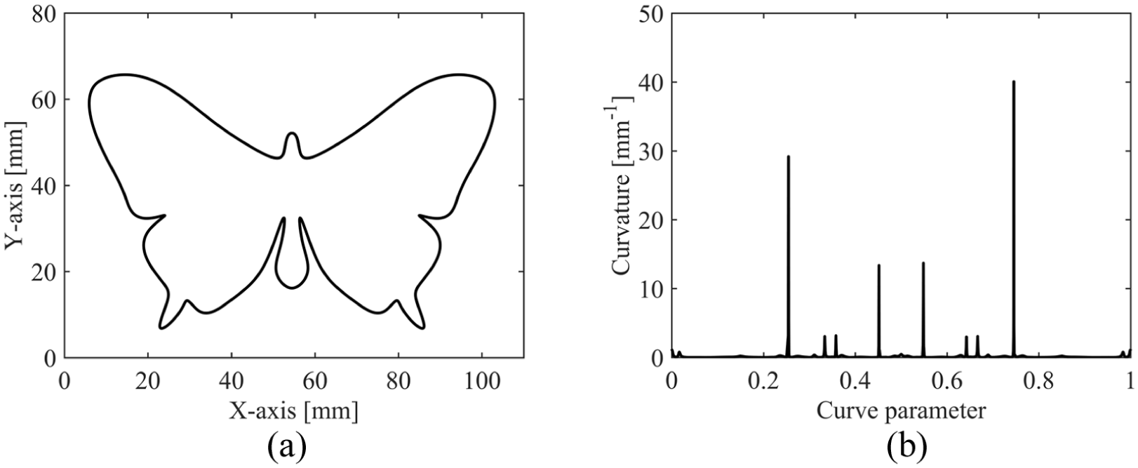
Butterfly curve: (a) planar butterfly curve and (b) curvature of planar butterfly curve.
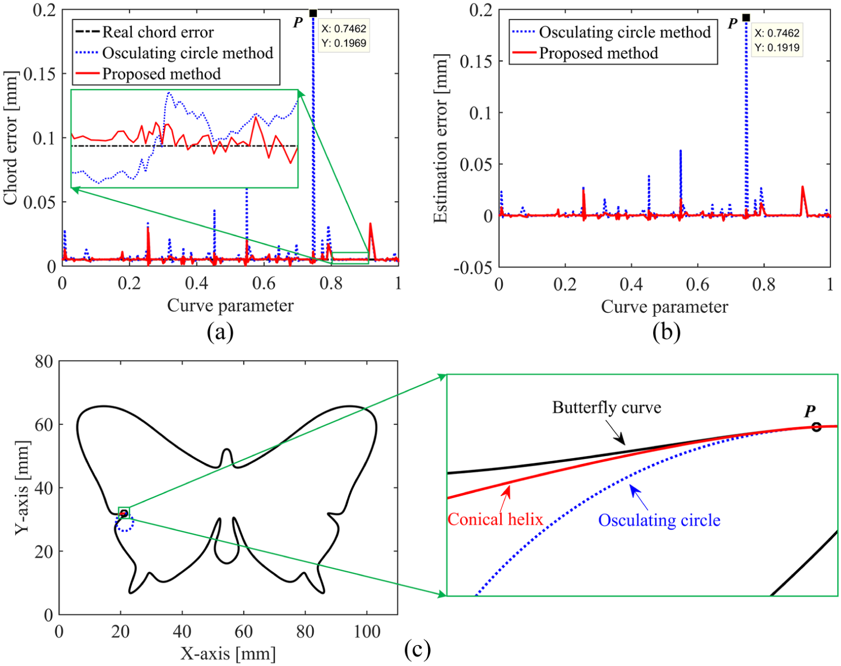
Chord errors of planar butterfly curve with δ0 = 0.005 mm: (a) real chord error and estimated chord errors provided by the osculating circle method and the proposed method, (b) estimation errors of the two methods and (c) detailed analysis of the maximum estimation error.
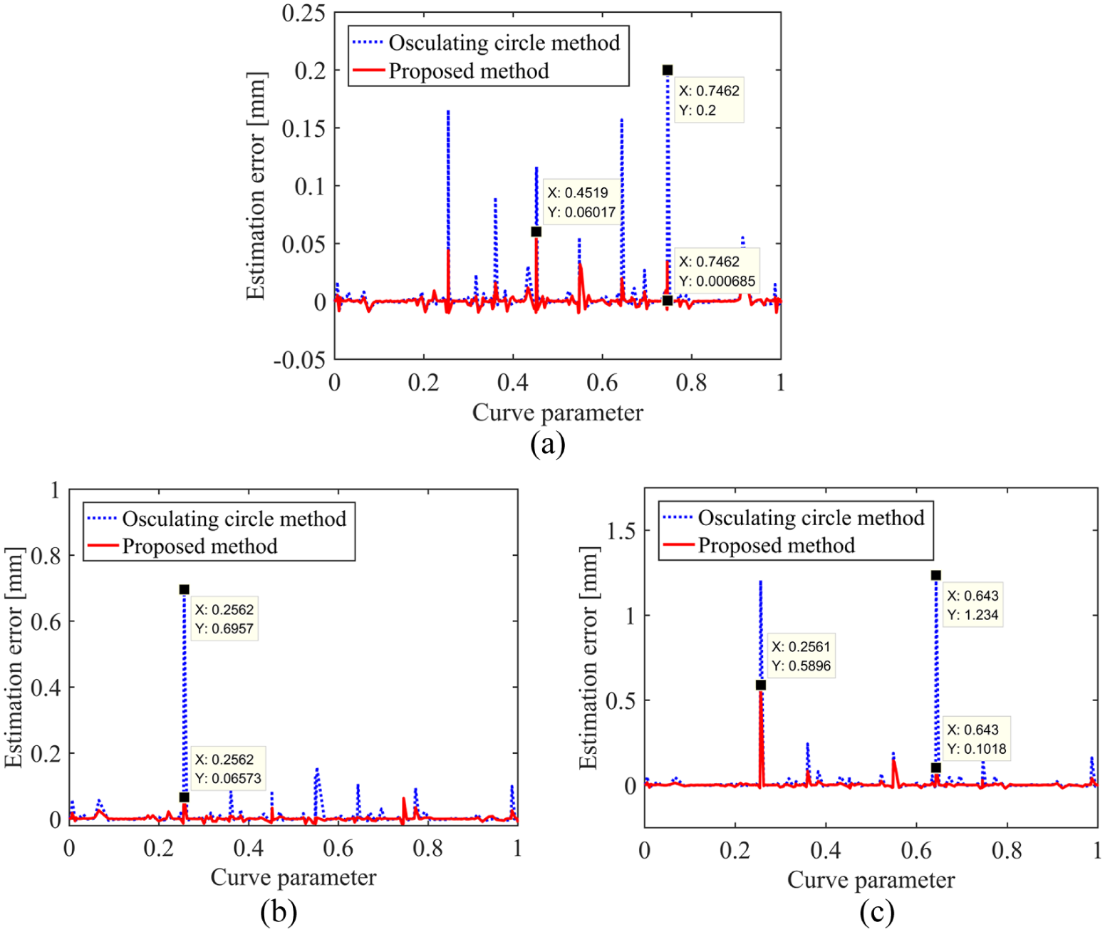
Chord errors of planar butterfly curve—estimation errors under different chord error constraints: (a) δ0 = 0.01 mm, (b) δ0 = 0.015 mm and (c) δ0 = 0.02 mm.
In addition, the estimation errors for the osculating circle method may reach to very large values even though the chord error constraints are very small. This is because the osculating circle cannot well approximate the freeform curve when the curvature variation is large. Take the cutter location point
Example 2
To demonstrate the effectiveness of the proposed third-order approach for spatial curves, a flower curve in Figure 8(a) is adopted, and its curvature and torsion are plotted in Figure 8(b) and (c), respectively. Simulation results for the osculating circle method and the proposed method are plotted in Figure 9(a)–(d). Compared with the osculating circle method, the proposed method improves the estimation accuracy significantly. The maximum improvement of the estimation accuracy is 84.95% when
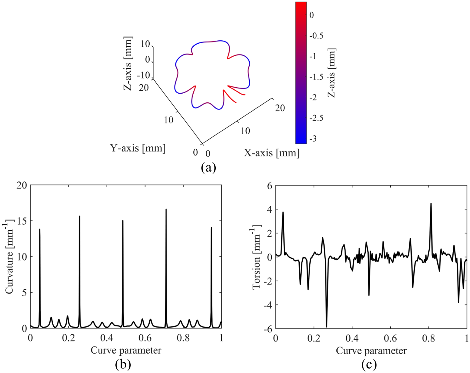
Flower curve: (a) spatial flower curve, (b) curvature of spatial flower curve and (c) torsion of spatial flower curve.
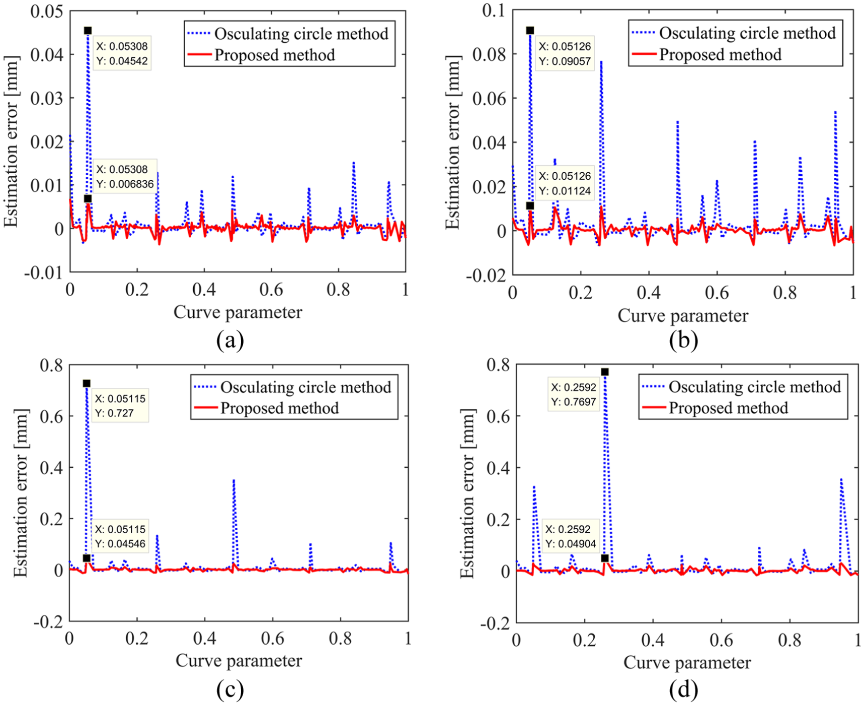
Chord errors of spatial flower curve—estimation errors under different chord error constraints: (a) δ0 = 0.005 mm, (b) δ0 = 0.01 mm, (c) δ0 = 0.015 mm and (d) δ0 = 0.02 mm.
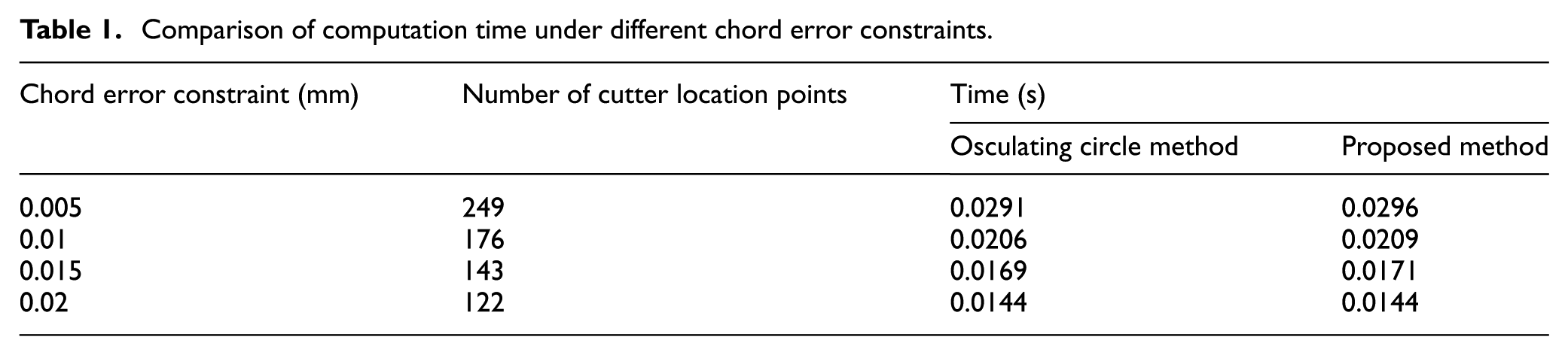
In addition, the proposed method is compared with the osculating circle method in terms of computation time to further demonstrate its effectiveness for practical use. Table 1 summarizes the computation time under different chord error constraints. The computation time is the mean value of the consumed time for 1000 trials. Although the proposed method needs to calculate the third-order derivative of freeform curve, the increase in computation time is little and acceptable considering the significant improvement of estimation accuracy.
Comparison of computation time under different chord error constraints.
Example 3
A spiral toolpath used for pocket machining is adopted as an engineering example to illustrate the effectiveness of the proposed method. The spiral toolpath and its curvature are plotted in Figure 10. About 476 cutter location points are obtained with
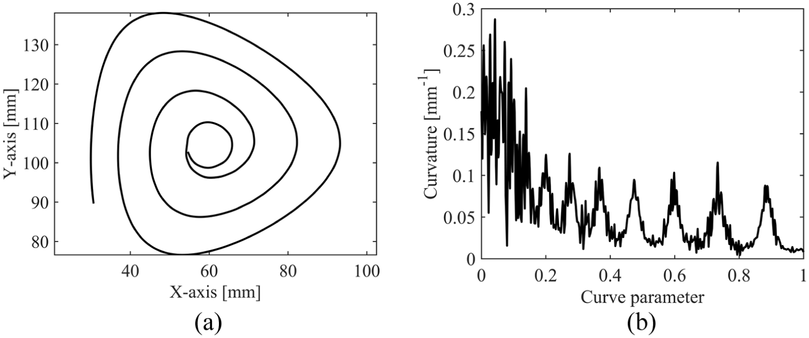
Spiral toolpath: (a) spiral toolpath for pocket machining and (b) curvature of spiral toolpath.
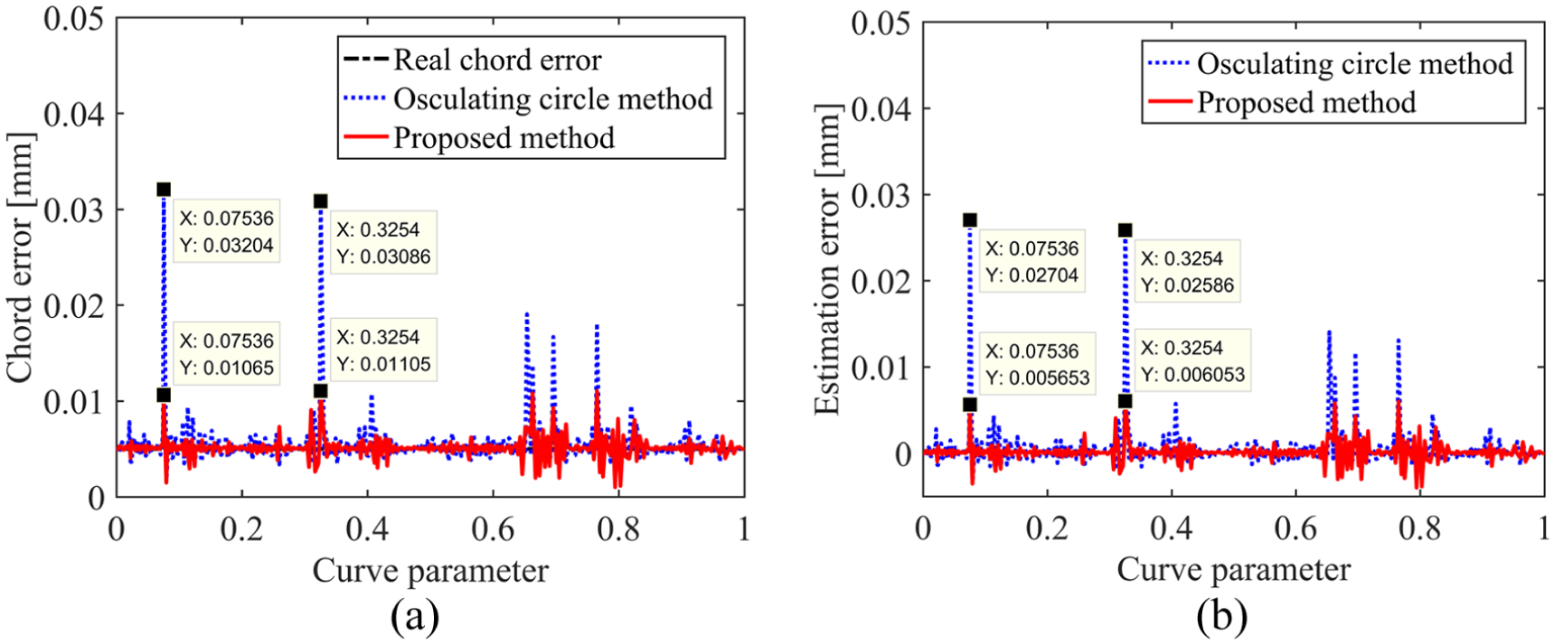
Chord errors of spiral toolpath with δ0 = 0.005 mm: (a) real chord error and estimated chord errors provided by the osculating circle method and the proposed method and (b) estimation errors of the two methods.
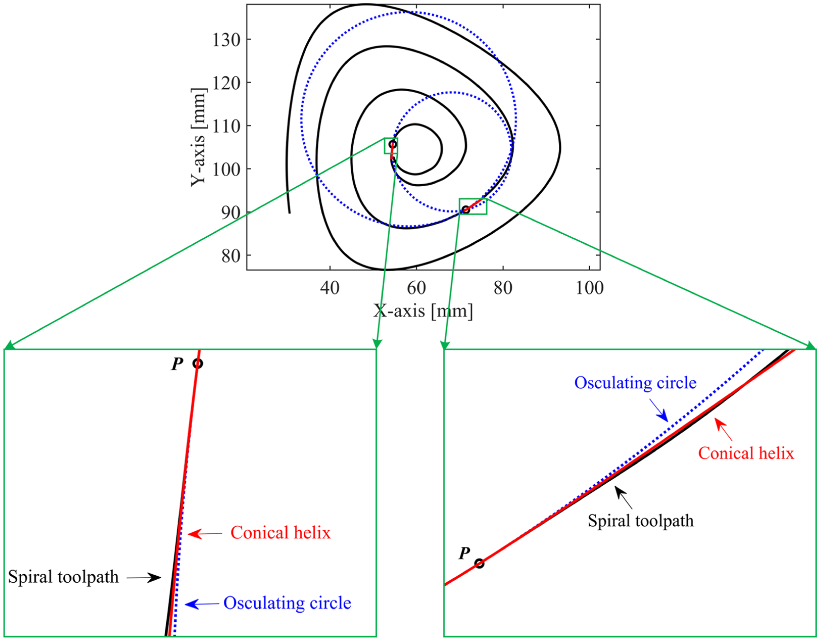
Enlarged views of cutter location points where maximum estimation errors occur.
Conclusion
Since the second-order chord error estimation only considers the influence of the curvature, it yields inaccurate estimation results for freeform curves. To consider the curvature variation and torsion, a novel third-order approach for calculating chord error of freeform curve is proposed. First, the geometric properties of the conical helix are investigated, and it is proved that a freeform curve can be third-order approximated by a conical helix. Second, with the aid of the conical helix, a third-order mathematical model for estimating the chord error of freeform curves is developed. Numerical examples for three freeform curves demonstrate that the proposed method can greatly improve the estimation accuracy in comparison with the second-order method.
Footnotes
Declaration of conflicting interests
The author(s) declared no potential conflicts of interest with respect to the research, authorship and/or publication of this article.
Funding
The author(s) disclosed receipt of the following financial support for the research, authorship, and/or publication of this article: This work was partially supported by the National Natural Science Foundation of China under Grant Nos. 51325502 and 91648202, and the Science & Technology Commission of Shanghai Municipality under Grant No. 15550722300.