
Abstract
Advanced manufacturing industries demand the embedded computer numerical control system having less vendor and hardware dependencies and more powerful computing capacity and intelligence. It is very important to build such an embedded computer numerical control system, and fortunately, PLCopen standard combined with Cloud Computing brings a brand new opportunity. Hence, this article presents an approach to fulfill those requirements based on PLCopen standard and Cloud Computing. A novel architecture of the embedded computer numerical control system is proposed, and the characteristics of the embedded computer numerical control system are discussed. The PLCopen standard is charged of real-time motion control, offering interoperability, feasibility, simplicity, and universality characteristics. The Cloud Computing technology is used to improve the system performance and to extend functions, overcoming the problem that the intelligence requirement is not compatible with limited hardware resource. A thermal error compensation experiment is described to illustrate the embedded computer numerical control system, and the result demonstrates that the PLCopen standard and Cloud Computing technology can be perfectly applied to the embedded computer numerical control system.
Keywords
Introduction
Computer numerical control (CNC) system, which is the core of advanced manufacturing technology, plays an important role in manufacturing and determines the functions and the performances of the CNC machine tools to a greater degree. Meanwhile, the embedded CNC system is widely used in the industrial field. In this article, compared with the CNC system based on PC or Industrial PC, the embedded CNC system specifically means a CNC system using an embedded central processing unit (CPU) for CNC hardware platform, such as ARM or embedded microcontroller (MCU). However, as a typical complex CNC system, the embedded CNC system confronts with a great of challenges because of its specific requirements as well as some recent development trends such as evermore complex products at lower prices and shorter development cycle. 1 First, under the needs of incessantly expanding demands and renewed technology of the machine tools, the embedded CNC system tends to advance toward the trend of powerful computing capacity and intelligence,2,3 but because of the limited hardware resource of the embedded device, a much more complicated system cannot be developed. Second, the embedded CNC system is usually used in a changing environment, such as in some small factories. Those applications need to be changed according to the different processes and the different workpieces or technology requirements. Therefore, the embedded CNC system should be reconfigured and reconstructed easily and quickly. Finally, the traditional complicated CNC system needs experts to operate and generate the execution codes, such as G-code, and the factory should spend more money on workers’ training. Thus, it cannot be accepted by the manufacture factory that the embedded CNC system has a complicated operation process.
These obstacles submit their requirements to their machine tool suppliers, which in turn transfer it to their control system suppliers. Hence, the control system plays a crucial role in fulfilling those requirements. For the first question, the Cloud Computing technology provides a great opportunity. The main thrust of Cloud Computing technology is to provide on-demand computing services with high reliability, scalability, and availability in a distributed environment. 4 The National Institute of Standards and Technology defined Cloud Computing 5 as a model for enabling ubiquitous, convenient, on-demand network access to a shared pool of configurable computing resource (e.g. networks, servers, storage, applications, and services) that can be rapidly provisioned and released with minimal management effort or service provider interaction. Dana Petcu et al. 6 proposed an approach for a new set of application programming interfaces (APIs) as Cloud application development is discussed from the point of view of portability. The current state of high-performance Cloud Computing technology has been discussed by Viktor Mauch et al., 7 and the underlying virtualization techniques and management methods have been proposed. Xiaoyu Yang et al. 8 proposed a business-oriented federated Cloud Computing model where multiple independent infrastructure providers can cooperate seamlessly to provide scalable information technology (IT) infrastructure and quality of service (QoS)-assured hosting services for real-time online interactive applications. The benefit of the scientific Cloud Computing from the economies of scale is discussed in Wang et al., 9 and the Cloud Computing usage model and the Cloud Computing platform are also discussed. Therefore, the Cloud Computing technology can be used to develop non-real-time services, while the limited hardware resource of the embedded CNC system is fully used to handle the real-time tasks.
For other questions, the IEC 61131-3 standard and the PLCopen standard provide a better solution. Modern programming methods provide tools to improve the intrinsic quality of software, that is, its correctness in the sense of reliability, robustness, integrity, persistence, and safety. 10 Integration, reuse, flexibility, and optimization are demanded to adapt to a rapidly changing and competitive market. In fact, standardization is a key factor to achieve these goals studied by Vichare et al. 11 The international standardization efforts have led to the definition of the IEC 61131 standard. The IEC 61131-3 defines a software model for defining automation projects as well as five programming languages. 12 Most of the programmable logic controller providers have accepted the IEC 61131 standard at different levels, and in order to achieve tool interoperability and reusability of the code, the international organization PLCopen has defined an open XML interface and the motion control library (MCL) based on the IEC 61131 standard. In this way, the generated application program has some characteristics, such as hardware independent, reusability across platforms, and changeability at different levels. The most important goals of this standardization are simplicity, efficiency, consistency, universality, flexibility, and completeness. 13 The advanced technologies have been used to build an embedded CNC system with one of those characteristics. Formal syntax of basic function blocks (BFB) is used in mathematical set theory to define a variety of elements of BFB as described by Tu et al., 14 and the semantics of BFB are described in two ways: denotational and execution semantics. Minhat et al. 15 proposed a novel open architecture of CNCs, which aims to provide some insight into a new generation of CNC with open, flexible architecture. Estevez et al. 16 remark that PLCopen can be used in different development phases during the whole life cycle of industrial control systems. Sünder et al. 17 provide an implementation of IEC 61131. Taking automation servo drive as an example, the feasibility of the service-oriented control by the use of the PLCopen standard has been demonstrated. The PLCopen standard obeys the IEC 61131-3 standard for programming languages and provides the standard interface specification, but in earlier studies, it has just been used as a programming language and how to use it alone is described. Hence, in this article, the PLCopen standard is used in an actual embedded CNC system, and the Cloud Computing technology is employed to improve the embedded CNC system’s capacity.
The contribution of this article is that an approach is proposed to improve the embedded CNC system’s performance. Based on the characteristics of the PLCopen standard and Cloud Computing technology, a novel architecture of the embedded CNC system is developed, and the objective is to develop an appropriate methodology with a feasible architecture for embedded CNC system, and the idea is illustrated in the following sections. The remainder of this article is organized as follows: In section “PLCopen MCL,” a brief introduction to the PLCopen standard is described. In section “Embedded CNC system based on PLCopen and Cloud Computing,” the architecture of CNC system is presented and the characteristics are also discussed. In section “Experiment and results,” a simple experiment is described and the results are discussed. Finally, this article is concluded in section “Conclusion.”
PLCopen MCL
The attributes such as motion control integration, reconfigurability, agility, maintainability, and connectivity to existed advanced technology have come to the forefront, while flexibility, time, and cost reduction are demanded to adapt to a rapidly changing and competitive market. 18 For these demands, standards are needed. PLCopen has generated such a standard. Currently, the whole specification of PLCopen concerning motion control consists of several parts. Part 1 13 consists of basic function library, which can be split up into administrative and control function blocks. Also it can be classified as single-axis function blocks and multi-axis function blocks according to the type of commands. In this article, we mainly concentrate on part 1, the BFB description.
Single-axis application in the PLCopen MCL
The PLCopen MCL is based on a state machine, such as initial state, standstill, homing, stopping, error stop, discrete motion, continuous motion, and synchronized motion 13 (Figure 1). The operation of the function blocks involves transition between these states, for example, the transition corresponding to the successful execution of the command MC_MoveRelative is from standstill state to discrete motion state, if the axis has been kept on the standstill before. When the axis has completed the command, then it returns to the state standstill except when aborted by other commands. The function blocks will have some operation modes, such as Aborting, Buffered, BlendingLow, BlendingHigh, and so on, and the Aborting mode is one important characteristic of the function blocks. If the function block’s operation mode is Aborting, it can be aborted by another function block during its running time, for example, during the execution of the function block MC_MoveRelative to a distance 10.0, which can be aborted by the execution of the function block MC_MoveAbsolute to absolute position 20.0, and the final result of execution is absolute position 20.0, without considering the result of function block MC_MoveRelative.
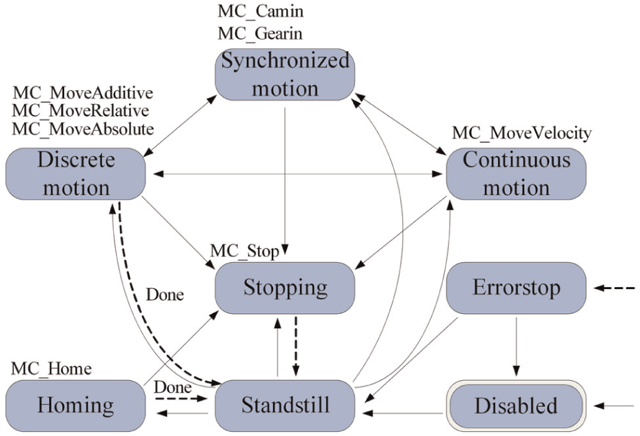
Single-axis state machine.
Multi-axis coordination application in the PLCopen MCL
The coordinated movement for multi-axis is supported by a set of function blocks in PLCopen MCL. The coordinated movement is composed of a master axis and one or more slave axes. The master axis could be a real or virtual axis, which is the final state; for example, in a Camming application, it remains in its state with a constant velocity running, but the slave axis changes its state to synchronized motion. The frequently used applications are Camming, Gearing, and Phasing. The application of Camming describes the position relationships between the master axis and slave axis, and the application of gearing describes their velocity relationships. Another important application of multi-axes coordinated movement is Phasing, providing a phase shift of the master axis to the slave axis. The Phasing can be used to shift the master axis in a relative position to the real physical position, which is observed only from the slave axis. Taking the Camming application as an example, the multi-axes application is described. The Camming application can be realized by function blocks MC_CamTableSelect, MC_CamIn, and MC_CamOut, and it needs only four steps.
The following are the implementation steps (Figure 2):
Step 1. The master axis and the slave axis (or slave axes) should be power on before, and these axes are usually in standstill state.
Step 2. The user or the application program should use MC_CamTableSelect to select one profile in tables established according to the real application in machine tools. The table identifier should be known by the master axis to read the profile data later.
Step 3. In this step, the main task is to calculate the slave motion profile. The velocity of master axis is always a constant, and the slave axis changes its state to synchronized motion. According to the Camming profile selected before, the slave motion profile should be provided corresponding to the master real position, which could be changed by scaling parameters and offset parameters. There may be several slave axes with different Camming profiles, and different motion profiles for the slave axes are provided. Usually, there will be a position error between master axis and slave axis, but the axes are able to follow the trajectory except unacceptable errors.
Step 4. The command MC_CamOut cancels the logical relationships between the master axis and the slave axes.
Process 1. The different axes will have different motion profiles, and the potential operation in this process is to transmit the Camming profile to the master used to calculate the slave axis motion profile.
Process 2. The Camming profile could be changed dynamically. If the slave motion profile needs to be changed, the function block MC_CamOut command is first executed, then the new Camming profile is selected, and the function block MC_CamIn command is executed again. The connection and disconnection between the master axis and the slave axes can be changed dynamically. Mostly, in this process, the user wants to execute MC_CamOut to finish the slave axis motion or separate itself from the master axis’s control.
Process 3. If the slave axis needs to be disconnected from the master axis, the function block MC_CamOut is executed, which could also be used to establish a new connection to the master or change the motion profile in Camming table.
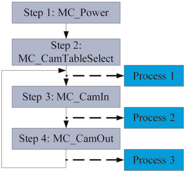
Flowchart of Camming.
The main function blocks about multi-axes motion have been described above, but the multi-axes application is not limited by these function blocks. In practical applications, these function blocks are usually combined with others, which could be a user-own function block. The advanced applications for the multi-axes listed in PLCopen MCL have Master Engine, Flying Shear, RotaryCut, and so on. 9 The most important is that the users could develop their own application function blocks, which is explained in the following sections.
Embedded CNC system based on PLCopen and Cloud Computing
Based on PLCopen MCL, we designed our embedded CNC system, and the Cloud Computing application was also used to extend the CNC system’s computing capacity and multi-service features. The typical topology of our embedded CNC system (Figure 3) is composed of the controller, controlled devices, and Internet service devices. The CNC system is constructed and compiled in a PC first and then the program is downloaded to the controller (CNC system hardware device). The tasks of a CNC system are characterized by concurrency, hybridization, and correlation, which make system implementation difficult. 19 In order to reduce the tasks running in the CNC system hardware device, the human–machine interface (HMI) is executed in remote devices or a remote PC connected by the fieldbus or Internet; also, we can add some Cloud Computing services to CNC system using the Internet.
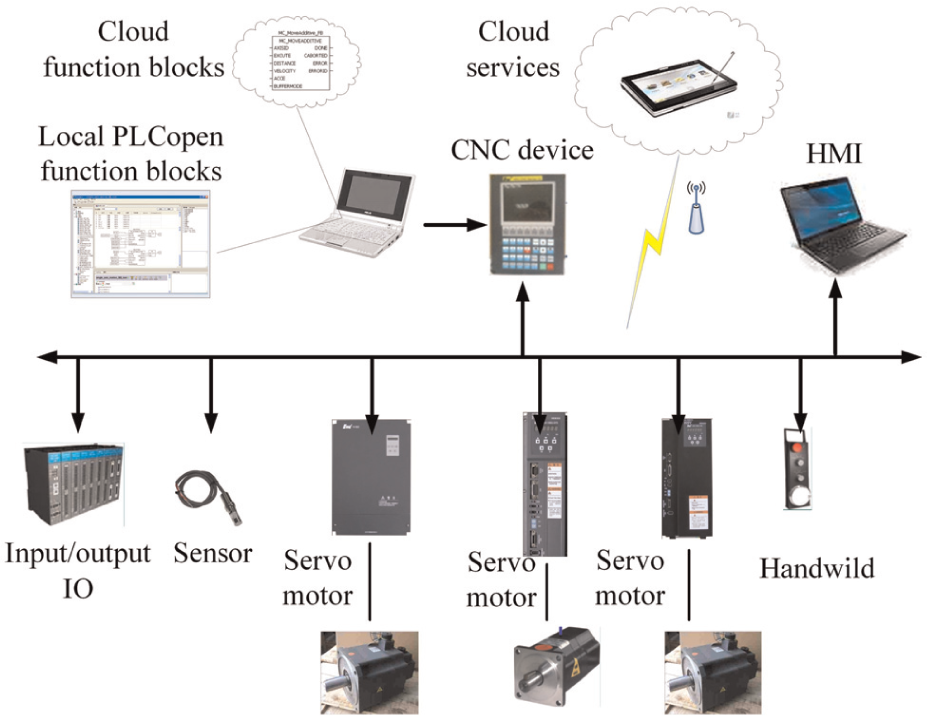
The topology of CNC system.
We can divide the CNC system into three layers (Figure 4) in this article: task layer, resource layer, and mapping layer. The task layer is consisted of motion control system, logic control system, intelligent application service, and monitor system or HMI. The resource layer is mainly about user’s function blocks, PLCopen function blocks, and Cloud resource. The aim of the mapping layer is data mapping and service mapping for different hardware or devices. For the convenience of understanding the structure of the CNC system in this article, we reconstitute the system with three blocks: Internet application block, local system block, and target application block.
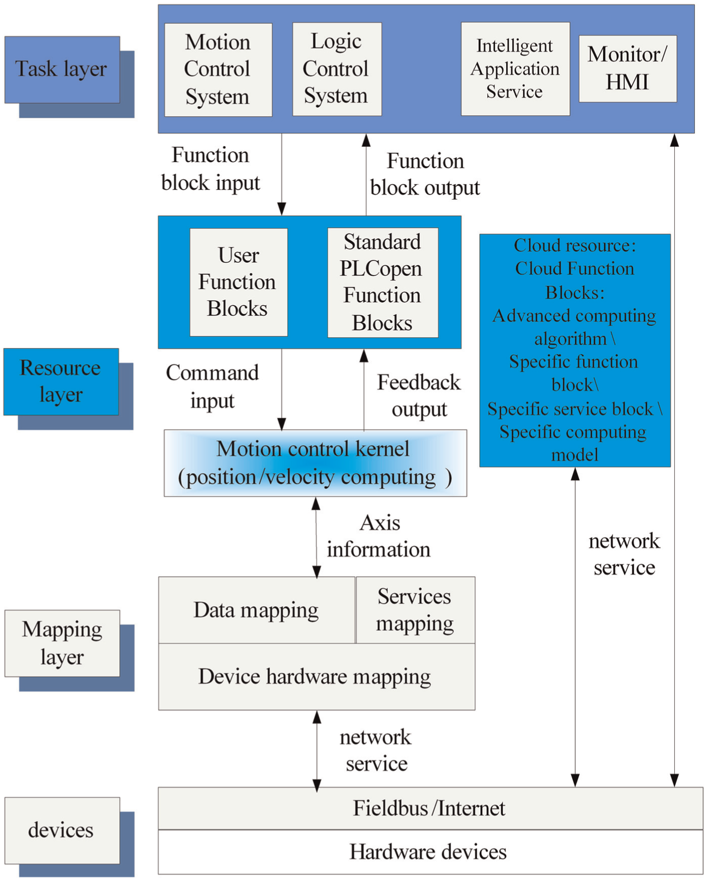
The CNC system architecture layers.
The Internet application block is composed of intelligent application service, monitor or HMI, and Cloud resource, and its basic function is to upload or download the intellectual property function block (IP block). The IP block may be a function, a function block, a combined function, or even an application program based on PLCopen basic models. The IP block can be generated on our platform by the developers who want to share their achievement safety with expected fees. The Internet application block can also be used to access the Internet monitor and control system via the Internet or fieldbus; in addition, some more advanced Internet technologies can be implemented in this block, such as Cloud Computing technology, and some non-real-time compensations can be considered as an application by Cloud Computing technology.
The local system block contains motion control system, logic control system, user’s function blocks, PLCopen function blocks, and motion control kernel, and it can be considered as a coding environment. The main phase of CNC system is completed in this block, such as feasibility and requirements phase, analysis phase, design phase, coding phase, and testing and maintenance phase. In this article, we used the most advantages of PLCopen standard combined with many users’ own function blocks to design a CNC system quickly and effectively. Before the development of a CNC system, we should acknowledge the motion control requirements. According to the requirements, we decide which PLCopen motion control function block to be used and the sequence to call the function blocks. If necessary, the unique user’s function blocks should be developed. Then, the function blocks are deployed as instances and their input and output variables are defined as global variables in the CNC system, as described in IEC 61131-3. After that, the application is compiled to generate the executable file, and the function blocks configure resource and device to be implemented on the system in the IEC 61131.
In the discussed CNC system, there are two questions to be considered: which function blocks to employ and when to call those function blocks. Also, the motion control algorithm is an important question, but it can be learned from the existing CNC system. The first question has been resolved as above mentioned. The motion control system and logic control system in the task layer are in charge of the second question: when to call the function blocks. After comprehensive analysis about the motion requirement and feedback information from the function blocks output variables, the motion/logic control executes or aborts the function blocks, keeping the axis in the accurate position. If the function block is executed and the command parameters are safe, it transmits the command parameters to the motion control kernel to compute the position and velocity command to the axes.
The CNC system designed in this article is constructed by PLCopen MCL, and Cloud Computing is used to extend the system function and to improve its capability. The CNC system resource contains about three parts: the PLCopen BFBs, the users’ own function blocks, and services function blocks shared by other users. The PLCopen BFBs are defined by PLCopen standard. The users’ own function blocks are developed based on IEC61131-3 standard or with C language. It is an important point in this article that the users’ own function blocks can be generated as an IP block, which can bring about much more advantages: the IP blocks can be generally used and protects the providers’ benefits; what’s more, the IP blocks can be generally popularized combining with Cloud Computing.
Sometimes, the developers may have a good idea about one complex problem in CNC system and may want to recommend it to others, and thus, they can make it as IP blocks according to the PLCopen standard, and other users can download it through the network, as application (APP) stores. The IP blocks can be conveniently released by Internet, such as APP store. The developers can upload their models to APP store, especially the complex algorithm about CNC system, and the customers can download the just application from the APP store.
The final layer, target application layer, is mainly about the data models about different devices. The codes generated in the local system layer can be applied in different devices; different devices have different hardware resources, and hence, there needs to be one layer to map the CNC system data models to the correlative hardware.
The variety of architecture of the embedded CNC system
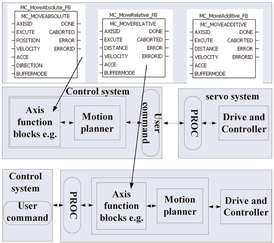
PLCopen standard can be used to harmonize the access of motion control functionality across platforms. With the standardization of the interface and the programming languages defined in IEC 61131-3 standard, the generated application program based on PLCopen function blocks is much more hardware independent and interoperable among different platforms. The features of PLCopen play an evident role in the architecture of the embedded CNC system, such as simplicity, consistency, universality, and flexibility. The PLCopen standard function blocks encapsulate their data and build-in functions, which are important for interoperation among different architectures; for example, the function blocks can be used in a centralized control system or a distributed control system.
PLCopen for motion is a structured programming method for creating motion applications that are hardware independent, interoperable, and scalable across different control solutions and architectures. The interfaces of the function blocks have been defined in PLCopen standard, and the CNC system can be built by assembling different function block modules by connecting the input interfaces or output interfaces. Modular applications can be reused and enhanced to simplify and ensure the quality of future projects. It can be considered that the PLCopen function blocks are not designed for a certain application, but they serve as a foundation for the diverse CNC systems. Therefore, different combinations of the BFBs can be used to build a new CNC system. As such, it is a feasible architecture for an embedded CNC system (Figure 5); each element of the PLCopen MCL can be used to build a new embedded CNC system according to the different conditions of the factory; also, in the case of administrative function blocks, these blocks are used to parameterize the servo drive or to provide access to axis information, such as the actual position.
A central and distributed control application for PLCopen.
By configuring the resource and device, the function blocks can be implemented on the CNC system or the autonomous servo system, and the function block network can be built as described in PLCopen standard or as an event-driven architecture in a distributed control system. In some cases, similar to the traditional CNC system, we can construct the CNC system in a central device by the PLCopen MCL and send the command to the servo drive, and the servo drive receives the position or velocity command from the fieldbus in each interpolation period. In some autonomous servo drive systems, the PLCopen MCL can be integrated inside. If the servo drive system receives the command, the local device has to execute the claimed action completely. Most important, some functions can be already modeled in the devices, which can be downloaded as an IP function block or vendor developed, such as (Proportion Integration Differentiation) PID parameters automatically set block or synchronization function block.
The simplicity and efficiency of programming with graph
The PLCopen standard just defines the input and output interfaces and their actions of the motion function block without realizing process, and the users can develop their own models based on PLCopen specification. According to the blocks’ interface specification, the function block diagram (FBD) language could be used to build a CNC system easily and efficiently.
Currently, the traditional CNC system is a complicated system, and the operators should be an expert who has been trained to handle many related technologies, such as G-code modes, the program environment, and the vendor-dependent development style. However, the PLCopen supports IEC 61131-3 specification, which can be easily learned by the developers or operators, without much more training. The training cost and additional costs can be reduced by standardization and simplicity within the programming environment. At this level, the knowledge about the CNC system architecture is transferred into program application. Standardization and simplicity of the program environment are reflected not only by the programming languages but also by the interfaces toward different motion control solutions and different suppliers. Programming by PLCopen motion library allows the developer to reuse the existing methods, expertise, and suppliers. In this way, the program is less hardware and vendor dependent; the reusability of the application software increases and the cost involved in training and support reduces. Compared with the traditional development progress of the CNC system, the function block programming offers a better interface, consistent accessing pattern, and easy usage. Hence, it can be used to decrease the development requirements and reduce the development cycle. The architecture of CNC system based on PLCopen standard is much more easily accepted by the industrial manufacturer.
The extended application based on Cloud Computing
The CNC system hardware has been improved with the development of science and technology, and the artificial intelligence plays a very important role in the CNC system, 2 but the existing CNC hardware cannot satisfy the requirements of artificial intelligence, which is evident in the embedded CNC system. Also, with wide usage of intelligent devices, these devices have a new requirement that there should be less interdependency between artificial intelligence and the hardware. 20 If the Cloud Computing technology can be applied to embedded CNC system perfectly, it will provide enough hardware resources and computing power to satisfy the new requirements.
The Cloud Computing technology is commonly associated with IT services, but it can be theoretically extended to the industrial field. Cloud Computing can transform the traditional manufacturing business model 21 to help factories to align product innovation with business strategy and to create intelligent factory networks that encourage effective collaboration. Tao et al. 22 introduced the concept, architecture, core enabling technologies, and typical characteristics of Cloud Manufacturing, as well as the differences and relationship between Cloud Computing and Cloud Manufacturing. Wang and Xu 23 present an interoperable manufacturing perspective based on Cloud Manufacturing, and the manufacturing resources and capabilities are discussed in terms of Cloud service. In Chandrasekaran et al., 24 the feasibility of using Cloud Computing for the optimization of machining processes is explored. Cloud Computing technology brings up a new opportunity for high-performance computing, high-automation, and multi-service function and service for the embedded CNC system (Figure 6).
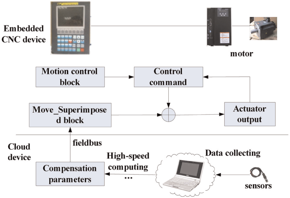
The Cloud Computing application in CNC system.
Cloud Computing could be applied in CNC system, especially in the embedded CNC system, but there are some obstacles. First, the Cloud Computing is a network application, and it has an indeterminacy transport delay. It is unacceptable for the motion control of the CNC system, which needs a high real-time performance, but it is better for an online non-real-time application, such as the thermal error compensation 25 and the parameter prediction and adjustment, and in those articles, the calculation can be done as the service in Cloud Computing. The Cloud Computing Cloud deals with compensation computing, and the other non-real-time function blocks in CNC system are charge of adding the compensation results to the motion control command.
Second, the interface between the CNC system and the Cloud Computing equipments is a problem. In a traditional CNC system, if you want to develop an interface to the Internet application, you should design the interface structure to suit the architecture of the CNC system, but different CNC systems have different architectures, and also to be taken into consideration is the property of the CNC system developer. Thus, the interface connecting to the network is nearly fixed in the traditional CNC system, which is limited by the architecture of the CNC system during its design. In this article, the Cloud Computing technology is mainly used as an online application for the non-real-time service, and the Internet interface is one important factor. Therefore, we make the best use of the PLCopen motion control function block, MC_MoveSuperimposed function block, as the interface to the Cloud Computing. The MC_MoveSuperimposed function block commands a controlled motion of a specified relative distance additional to an existing motion but cannot influence the existing motion. In the embedded CNC system, the axis is controlled by one or more PLCopen motion control blocks, except the MC_MoveSuperimposed block. The MC_MoveSuperimposed function block is used to add the compensation computing results to the axis motion. The compensation algorithm is executed in Cloud Computing devices, and the Cloud Computing devices can access to the embedded CNC system using the Internet. In summation, the PLCopen MCL provides a convenient architecture to construct a CNC system and a feasible interface to connect much more function application by Cloud Computing.
Experiment and results
In order to verify the system performance based on PLCopen and Cloud Computing in our article, we designed an experiment which is used in thermal error compensation about machine tools. The thermal error compensation is calculated by Cloud Computing technology, which can be considered as a Cloud Computing service, and the results are transmitted to the embedded CNC system by network or fieldbus. The experiment is designed to verify two points: first, the performance of the embedded CNC system based on PLCopen standard as described in our article; second, the embedded CNC system combined with Cloud Computing has a powerful computing ability and which can be implemented as described in our article.
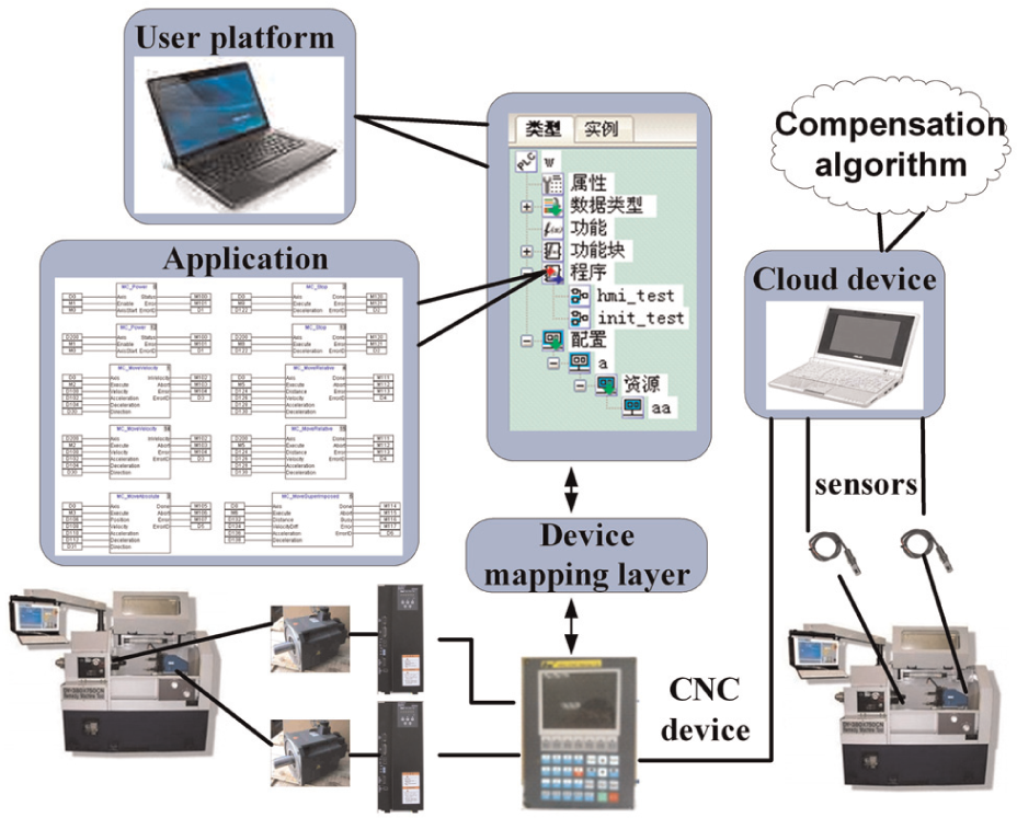
The CNC system has two axes with the thermal error compensation (Figure 7). The CNC system is composed of the motion control function and error compensation function. The motion control function is based on PLCopen MCL, and the compensation function is appended to the CNC system by a function block MC_MoveSuperimposed. The sever motors are connected to the embedded CNC system by the fieldbus. The MCU of the embedded CNC system is ARM 2440, the frequency is 200 M, and the RAM is 512 M, the bandwidth is 100 M/s. The temperature sensors are fixed on the machine tools, and the temperature range is 0 °C–100 °C, which can be converted into the voltage signal from −12 to +12 V. The temperature variation is acquired by the change of the voltage, the voltage is converted to the digital signal, and then the digital signals are transmitted to the data collecting models in the Cloud. After the signals are analyzed by the special compensation model and algorithm, the compensation results are added to the motion control system. The experiment is completed by several steps:
The CNC system is built in the PC based on PLCopen MCL.
According to different hardware, different device mapping functions are chosen.
The CNC system is compiled and downloaded to the target device through USB or Serial Port.
Execute the program in target device until the command is stopped, and the Cloud Computing devices collect the information from the sensors fixed on the machine tools.
The error compensation algorithm is executed in Cloud Computing devices, and the online compensation is computed at a relative distance.
Transmit the error compensation to the CNC system periodically until the CNC system is stopped.
The error compensation computing will be run at all times, except when an unacceptable error occurs in the system.
The architecture of the embedded CNC system in this experiment.
In this experiment, the compensation algorithm model and complexity do not have a direct influence on the CNC system architecture described in our article; thus, we have just done a simple compensation through the Cloud Computing, a relative distance with a trapezium velocity plan is added to the axis motion control command. First, the basic function of the embedded CNC system is tested, and the velocity or position curves in different commands in accordance with PLCopen motion control function block specification are presented (Figure 8), where the horizontal axis presents the data acquisition time, and the vertical axis presents the velocity (pulse numbers per interpolation period) or position.
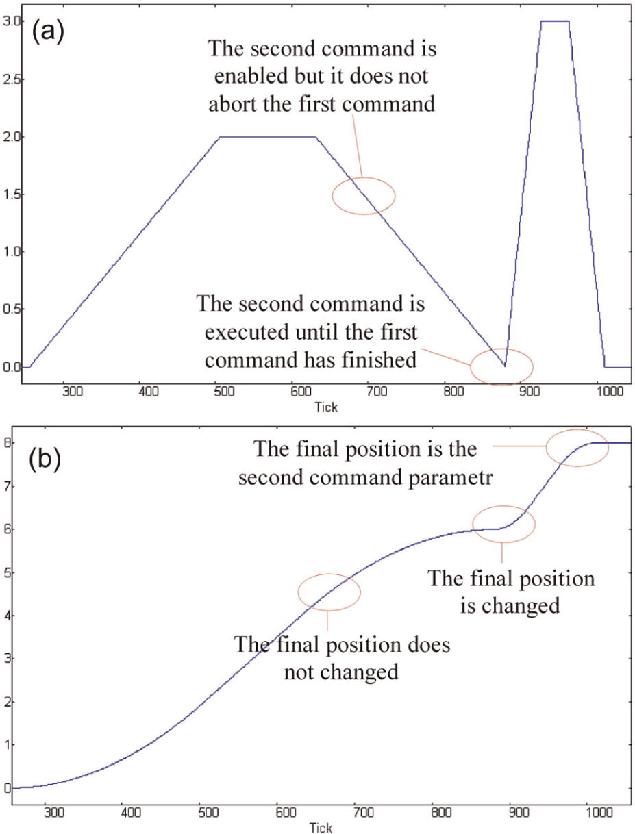
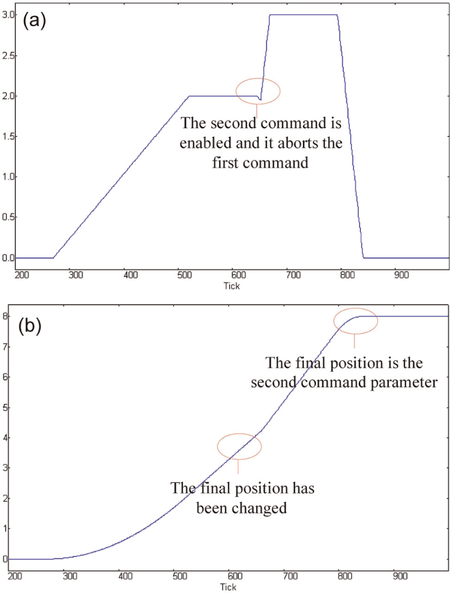
The (a) velocity and (b) position curves in buffered modes.
In traditional G-code description, G01 represents an absolute motion control or a relative motion control. The same commands can be provided in the PLCopen standard, such as MC_MoveAbsolute and MC_MoveRelative. Meanwhile, in order to decide the execution relationship among different commands, some of the function blocks have an input interface called “BufferMode.” In Figure 8, the two commands represent an absolute motion command, and its “BufferMode” is “Buffered,” which means the next function affects the axis as soon as the previous movement is done. At the sampling point 650, the second command is enabled while the first command is ongoing, but the motion control parameters are not changed immediately and the second command is not executed until the first command has been finished at the sampling point 880.
In Figure 9, the two commands represent an absolute motion command, and its “BufferMode” is “Aborting,” which means the next function block aborts an ongoing motion and the command affects the axis immediately. An unfinished motion command can be discarded to execute the next motion command, and it is different from the sequential execution of G-code. At the sampling point 650, the second command is enabled while the first command is ongoing, at the same time, the motion control parameters are replaced by the second command immediately and the unfinished movement is discarded, and the axis is controlled by the second command. Contrary to Figure 8(a), the velocity is not replaced until the first command is finished; in Figure 9(a), the velocity is replaced once the second command is enabled.
The (a) velocity and (b) position curves in Aborting mode.
Second, the error compensation is verified; the velocity, position, and the compensation variables are figured in our monitor software (Figure 9). In the experiment, the axis is controlled by a relative distance command with a trapezium velocity plan. Once the velocity reaches the maximize value, it will remain at fixed speed. If the compensation results are added to the motion command, the axis velocity will be changed.
Figure 10(a) is the velocity curve, and at sampling point 700, as shown in the oval-shaped curve, the compensation result is added to the axis command, and the velocity is changed. Figure 10(b) is the position curve; the oval-shaped curve also shows the enlarged details that the two red lines present the position variable before and after the compensation, and we can seen that the position is changed during the compensation. Figure 10(c) is the compensation position variable; the compensation position is added to the motion control command when the compensation command is enabled. The architecture of the embedded CNC system is verified by the online non-real-time thermal error compensation experiment, and the experiment proved that it is useful to develop the embedded CNC system with an open and robust architecture by the PLCopen function blocks and Cloud Computing technology.
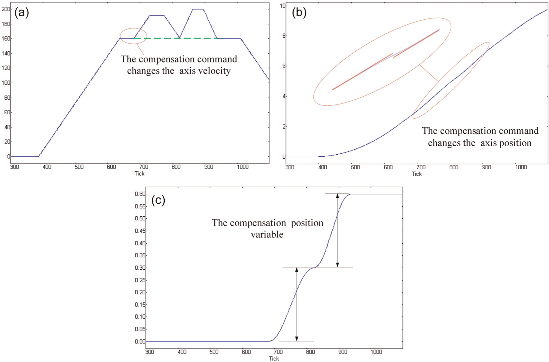
The (a) velocity curve with compensation, (b) the position curve with compensation, and (c) the compensation variable curve.
Conclusion
Currently, the motion control market is a fragmented market with a wide variety of incompatible systems and solutions. Using motion control means that the motion control architecture needs to be selected, inhibiting the reuse of the application code, and has to adapt different levels of machines. All these bring about many obstacles for the system developers. Hence, this article presents a solution to build a novel CNC system trying to solve these problems.
In this article, we present a new structure of embedded CNC system based on PLCopen standard and Cloud Computing. PLCopen is a vendor- and product-independent worldwide association. The applications of this standard provide a standardized programming interface in the industrial motion control field and have been accepted by most industrial developers, and therefore, it allows people with different backgrounds to create different parts of a program project during different phases of the development life cycle. The Cloud Computing technology has been in existence earlier, and it has now been verified that it can be used to improve the computing capacity. With the advantages of these two technologies, the proposed embedded CNC system is feasible, along with reusability, interoperability, and configurability characteristics. The thermal error compensation experiment indicates that the embedded CNC system has a simple architecture and the advanced technology can be applied to improve its computing capacity.
Footnotes
Declaration of conflicting interests
The authors declare that there is no conflict of interest.
Funding
This work was supported by the National Natural Science Foundation of China (Grant No. 50905069), the National Science and Technology Major Project (Grant No. 2012ZX04001012), and the National Science and Technology Major Project (Grant No. 2012ZX04001022).