
Abstract
Shaping of the difficult-to-machine non-conductive materials such as glass, quartz and ceramic is much difficult and uneconomical by existing machining processes. As a result, wide applicabilities of these materials are still limited. Even though these materials are highly required in the field of the modern industries. To overcome the problem, a new machining method has been proposed by researchers by combining the features of electro-chemical machining and electro-discharge machining. Such combined machining process is called as electro-chemical spark machining process. Such developed machining method becomes an appropriate process for machining of non-conductive materials with significant improvement in productivity as compared to the electro-discharge machining and electro-chemical machining processes. In this article, the role of electro-chemical spark machining for machining of the non-conductive materials has been summarized and focused on the future research possibilities in the same area. This article also focuses on mechanism, process and performance parameters, variants and new developments related to the electro-chemical spark machining. As a result, this review article becomes beneficial for researchers to understand the phenomena of the electro-chemical spark machining process as well as further development in the same area.
Keywords
Introduction
The electrically and thermally non-conductive materials such as ceramics, quartz, Pyrex, glass, silicon and composites are widely accepted in various fields of engineering such as mechanical, electrical, electronics, computer, biomedical and nuclear. These materials possess several specific characteristics such as high hardness, electrical and thermal insulating properties, chemically non-reactive and high melting temperature to make them suitable for advanced industries.1–3 These materials are used to make various insulating products related to the electrical and thermal systems and also for micro-reactors, micro-pumps, micro-accelerometer and drug delivery devices.4,5 The non-conductive materials such as glass possess translucent properties and are used in different forms such as optical, window, laboratories, container, light bulb, fiber glass for industrial applications, micro-devices such as solid oxide fuel cells, pumps and reactors.3,6
The machining of these materials is still a challenge for manufacturing industries due to unusual properties such as hard and brittle nature. Therefore, the shaping of such materials is still difficult or uneconomical, when conventional machining processes are applied.7,8 On the other hand, unconventional machining processes are being explored for their potential for shaping of difficult-to-machine materials. Generally, both types of materials (electrically conductive and non-conductive) are effectively machined by selection of appropriate unconventional machining techniques. Even though these processes show their own weakness in different conditions such as micro and nano machining. Generally, more industrialized processes such as electro-discharge machining (EDM) and electro-chemical machining (ECM) are widely applied for shaping of electrically conductive materials.9–12 Instead of this, various unconventional machining techniques such as abrasive jet machining (AJM), ultrasonic machining (USM) and laser beam machining (LBM) are extensively used for machining of such materials. Even though poor surface quality (SQ) and low machinability are several inherent problems that limit the wide applications of these materials in the field of advanced engineering.13–15 Therefore, researchers combined the EDM and ECM processes to meet the above challenges and such a combined/developed process is known as electro-chemical spark machining (ECSM) process.
ECSM
ECSM process is a novel combined/hybrid machining method developed to machine electrically non-conductive materials. Generally, it comprises thermal energy based on two unconventional machining processes, that is, ECM and EDM.15–17 In other words, it is an emerging unconventional method, or non-contact machining method that involves melting, vaporization and chemical etching simultaneously to raise the productivity of the ECSM process. Due to the combined effect of EDM and ECM, the ECSM process successfully overcomes the drawbacks of the constituting processes (EDM and ECM) as requirement of the electrically conductive materials for machining. The process capabilities are not only limited to non-conductive materials and also applied for shaping of electrically conductive materials.17–19 Generally, process capability in terms of material removal of ECSM process is much higher (approx. 5 and 50 times) as compared to ECM and EDM, respectively, at same machining conditions. 20
Due to the combined effect of ECM and EDM in machining, the ECSM process becomes highly complex and the complexity is reflected by diversity in the name related to such machining process. Initially, Kurafuji and Suda 16 presented the ECSM process as electro-chemical discharge (ECD) drilling during making of micro-hole into glass. Subsequently, several names of the ECSM process were used by researchers such as discharge machining (DM) for non-conductors by Cook et al., 21 electro-chemical arc machining (ECAM),20,22 electro erosion-dissolution machining (EEDM), 17 electro-chemical discharge machining (ECDM),15,23–27 spark-assisted etching (SAE), 28 spark-assisted chemical engraving (SACE)29–31 and ECSM.18,32–37 It has been observed that ECDM and ECSM are frequently used by researchers. Therefore, a single name as ECSM has been used throughout this article to avoid intricacy and to simplify the process for easy understanding about process behaviors. In the same way, to understand the clear distinction of ECSM with constituent processes (EDM and ECM), a comparative study has been summarized in Table 1.38–53
Comparison between ECM, EDM and ECSM.
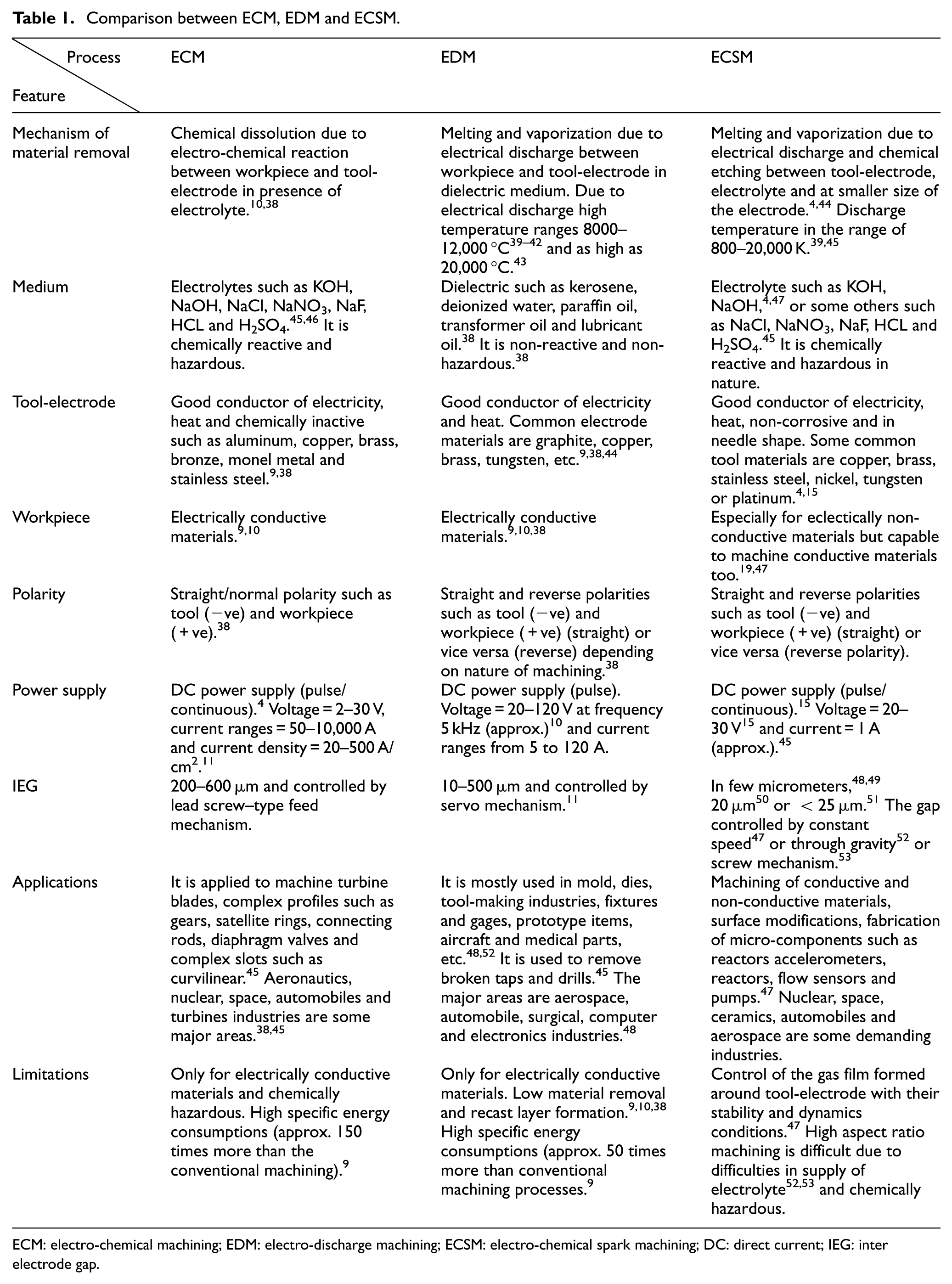
ECM: electro-chemical machining; EDM: electro-discharge machining; ECSM: electro-chemical spark machining; DC: direct current; IEG: inter electrode gap.
Theories of ECSM process
ECSM is a complex process that is effectively applied for machining of non-conductive materials, but the mechanism of ECSM process has not been clearly understood by researchers till now. Even though its applicability for machining of non-conductive material has been proposed in 1968 by Kurafuji and Suda. 16 Several researchers have tried to explain the phenomenon of ECSM process during studies. Crichton and McGeough 22 in 1985 claimed that the growth of gas layer and local variance of electrolyte flow patterns such as flow stagnation and eddy formation are responsible for discharge between tool-electrode and electrolyte interface but they were unable to explain the basic causes of electrical discharge phenomenon of ECSM process.
Basak and Ghosh 53 in 1996 considered that spark formation of the ECSM process is analogous to switching off mechanism occurring in the electrical circuit. According to this, bubbles’ density around the tool-electrode increases up to critical voltage and the substantial flow of current is responsible for the formation of vapor blanket surrounding the tool surface due to high Ohmic heating. Suddenly, the bubbles blow-off due to intense heating upon which the current drops to zero (switching off phenomenon) by discharge within a very short period of time. This cycle is repeated during machining process due to frequent contacts between tool and electrolyte. Still, this theory is unable to explain the spark formation mechanism of ECSM process. The spark formation phenomenon is explained as anode effect by Vogt. 54 According to this, the phenomenon of the immediate breakdown of electrolysis fluid occurs without any interference from outside due to formation of gas film around the tool-electrode. As a result, machining take places during ECSM process. Jain et al. 32 proposed that the gas bubbles formed during the ECSM process behave like valves and responsible to produce discharge in the form of spark after breakdown occurs in electrolyte fluid. But still this mechanism is unable to explain the basic reasons for no-spark/discharge formation in deeply immersed tool-electrode in electrolyte fluid.
Yang et al. 55 considered the ECSM phenomenon as a high-temperature etching process during micro-hole drilling into borosilicate glass and tried to explain the chemical etching effect experimentally. Kulkarni et al. 56 in 2002 proposed that discharge phenomenon similar to arc incident occurs in gas. They considered that gas bubbles are combined with each other and finally form a single gas bubble. These gas bubbles isolated the tip of tool-electrode from the electrolyte medium resulting in local electric field gradient at tool–electrolyte interface which becomes more than breakdown limit where electrical arc/discharge takes place. Wuthrich and Bleuler 57 in 2004 considered that the bubbles coalescence based on percolation theory. According to this, the smaller bubbles are detached from the surface of tool-electrode comparatively in a longer time. On other hand, bigger size of bubbles are formed after coalescence of smaller sizes of bubbles and finally strongly attached with the tool surface due to capillary action resulting formation of gaseous layer. This gaseous zone is responsible for the electrical discharge during ECSM, but it also unable to clarify the spark phenomenon of ECSM process. Instead of this, the spark has not been generated with highly immersed surface of tool-electrode into electrolyte which is an unsolved phenomenon of ECSM process.
Bhondwe et al. 34 in 2006 and Panda and Yadava 18 in 2009 proposed a finite element method (FEM) model for ECSM process. They considered that material has been removed due to sparking but were unable to explain how sparks are generated during machining. Jiang et al. 58 considered that formation of gas layers was responsible for spark creation during ECSM process. They identified that spark generation is a highly complicated phenomenon with cylindrical tool-electrode due to fringing effect while tapered tool-electrode has been found more convenient for spark generation. They also claimed that sparks are not generated at higher supply voltage than critical voltage due to volatility in the formation of gas layer in the transient phase. In this situation, chemical etching process is in dominating phase and machining highly depends on it. Behroozfar and Razfar 59 proposed that chemical etching is responsible for machining during ECSM process. They considered that simultaneous images of current signals are responsible for the shape of arc/discharge and a signature engraves on the workpiece. The impingement in arc raises the temperature of electrolyte medium, which supports chemical etching and as a result the material is removed from the workpiece surface.
Spark formation phenomenon of ECSM
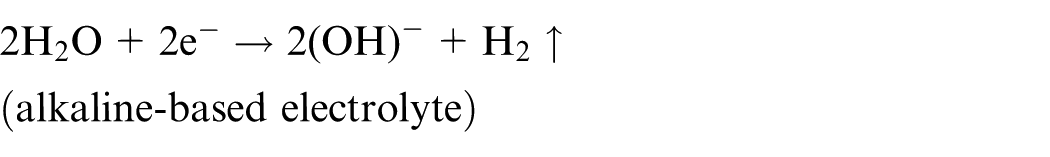
In ECSM process, the combined effects of constituent processes (ECM and EDM) are responsible for material removal. Generally, hydrogen (H2) gas bubbles are generated due to electrolysis process or electro-chemical reaction while electrical discharge/spark is produced between gaseous layer formed by gas bubbles and tool-electrode (cathode) in the presence of electrolyte. Therefore, two phenomena, that is, hydrogen (H2) gas formation and spark generation, cause material removal in ECSM. The material is removed due to simultaneous effect of melting, vaporization and chemical etching processes. In other words, the material removal is equal to the sum of material removed by spark erosion and chemical etching. Generally, a dense, uniform and stable gaseous layer is preferred for machining while unstable gaseous layer leads to unstable spark formation.
Of course ECSM is a highly undefined process and it covers a long journey, and many different configurations such as sinking ECSM, drilling ECSM, milling ECSM, traveling wire (TW) ECSM and turning ECSM are developed by researchers but spark formation is still an unknown phenomenon. In this section, spark formation phenomenon has been explained considering the bubbles’ conversion mechanism into gaseous layer, and spark generation is similar to arc formation in gaseous environment. The schematic view of ECSM process is shown in Figure 1. In this process, two electrodes of different (smaller to larger electrode surface approx. 1:100) sizes are used for electro-discharge action. The smaller size electrode is known as tool or tool-electrode or cathode and made of chemically non-reactive materials such as copper, brass, stainless steel, nickel, tungsten or platinum.4,15 The tool-electrode is dipped (approx. 2–3 mm) into the electrolyte such as sodium hydroxide (NaOH) or potassium hydroxide (KOH) from the top surface of the electrolyte fluid. The larger electrode (made of graphite) is known as auxiliary or anode and kept away (approx. 25–50 mm) from the cathode or tool-electrode in the machining chamber.
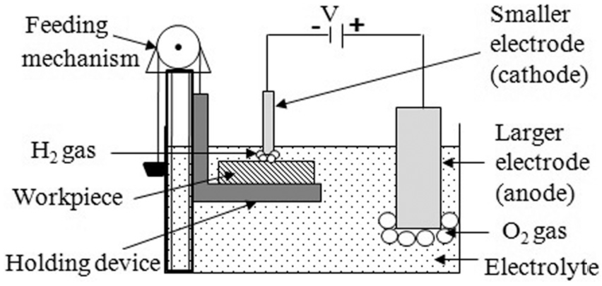
Basic configuration of ECSM process.
Initially, a direct current (DC) voltage (continuous or pulse) has been applied between anode and cathode in the presence of electrolyte medium. Generally, pulse DC voltage has been preferred for machining because it gives better surface quality (SQ) as compared to the continuous DC supply. Even though constant DC supply is beneficial for uniform generation of H2 gas bubbles. Generally, electro-chemical reactions take place at anode (auxiliary electrode) and cathode (tool-electrode) surfaces in the presence of electrolyte fluid due to potential differences caused by the generation of H2 and oxygen (O2) gases at the tool-tip and auxiliary electrode surfaces positively as shown in Figure 1.
Generally, two chemical reactions (dissolution of metal in electrolyte and evolution of oxygen gas at anode surface) occur at interface surface of the anode (auxiliary electrode and electrolyte). 4 The dissolution of metal or anodic material into electrolyte solution occurs as

where M is the anodic material/metal and Z is the number of ions (positive/negative).
These metallic ions combined with hydroxide of electrolyte fluid and formed insoluble metal hydroxide precipitates as follows

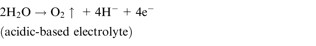
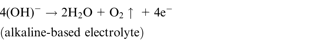
Generally, the electrolyte fluid used in ECSM process may be acidic or alkaline-based solution. Thus, chemical reaction occurs at interface of the anode-electrolyte as a result of O2 gas generated at anode surface as follows
The chemical reaction for generation of bubbles (H2 gas) surrounding the surface of cathode (tool-electrode) in the presence of electrolyte solution occurs as

The neutralization of positive charge metal is caused by chemical reaction as


Generally, H2 gas bubbles generated during electro-chemical reactions are responsible for the formation of electrical discharge/spark phenomenon. The size of gas bubbles is very small between 25 and 55 µm at a supplied voltage of 30–60 V at lower (<10 Ω) value of electrolyte resistance. The different phases of ECSM process for spark generation are shown in Figure 2. Generally, the density and mean radius of H2 gas bubbles depend on the DC supply voltage and it increases with an increase in the supply voltage. An increase in the voltage leads to the generation of bubbles (H2 gas), and as a result the density of gas bubbles increases. Due to this, the bubbles bonded together upon which the mean diameter of H2 gas bubbles increases. Finally, a gaseous film/layer has been established near the surface. The thickness of gaseous film is about 50–100 µm for a typical cylindrical tool-electrode of diameter 1 mm. 15 The gaseous layer acts as a dielectric medium between tool-electrode and electrolyte fluid. The gaseous environment isolates/protects (direct contact) the tool-electrode surface from the effect of electrolyte fluid and becomes an electrically conductive medium, when a critical value of the supplied voltage has been reached through tool-electrode to the electrolyte fluid.
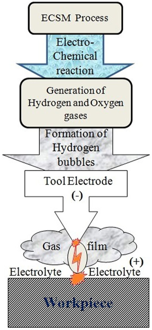
Different phases of ECSM process.
The electro-chemical spark phenomenon of ECSM is analogous to arc formation in gas. 53 In ECSM process, the spark takes place between tool-electrode, gaseous film and electrolyte at higher value of current density than critical value (approx. 1 A) 48 and the supply voltage is also higher than the critical value. The typical value of critical voltage is approximately 30 15 or 25 V. 45 The spark formation is shown in Figure 3. The electrolyte concentration, type of electrolyte, conductivity and tool geometry are highly influencing factors that affect spark generation. Due to flow of high-density current above the critical value, high electrical field (approx. 106–108 V/m) is developed in the gaseous zone. 39 As a result, H2 gas has been ionized and free ions (+ve and −ve) move toward opposite electrodes (cathode or anode) and formed the plasma channel as shown in Figure 3. The temperature of plasma channel is in the range of 800–20,000 K.39–43 At this temperature, any non-conductive material is placed near the sparking zone with appropriate inter electrode gap (IEG) and then material removal takes place from workpiece surface due to melting and vaporization. Such phenomenon is known as material removal mechanism of ECSM process. Generally, IEG between tool-electrode and workpiece is in few micro-meters and depends on the machining conditions. The IEG between tool-electrode and workpiece is 20 µm 50 or less than 25 µm for machining of glass. 50 The IEG between tool-electrode and workpiece has been maintained constant during machining and controlled by different devices such as spring fed slider mechanism, 14 constant speed, 46 through gravity feed 49 or screw feed mechanism. 52
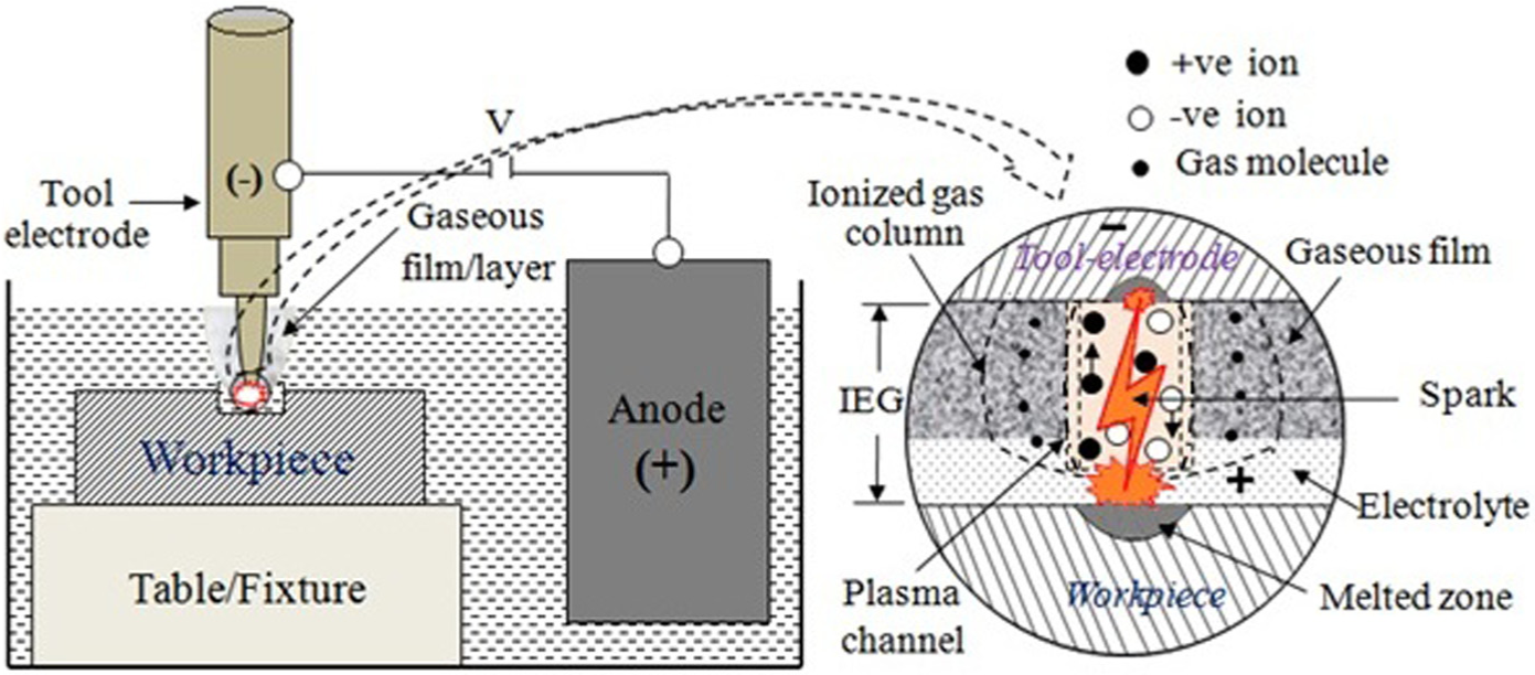
Spark formation phenomenon of ECSM.
Generally, spark phenomenon occurs only below (2–3 mm) the electrolyte surface. Moreover, spark generation does not take place when the tool-electrode has been immersed deeper into electrolyte fluid. Generally, percolation theory is responsible for the formation of gaseous layer around the tool surface. 55 According to this, the bubbles are detached from the surface of tool-electrode as long as small. Even though bigger size of bubbles are formed after coalescence of the smaller sizes of bubbles and strongly attached with the tool surface due to the capillary action and as a result forming gaseous layer. Such a phenomenon is responsible for sparks generation. The other situation, while spark is not generated (tool-electrode immersed deeper into electrolyte) as shown in Figure 4. The current flows from anode to cathode to electrolyte to anode and H2 gas bubble formation takes place due to chemical reaction. These bubbles are moving in the upward direction and are collected near electrolyte surface around the tool-electrode. In this incident, the bonding between the gas bubbles is negligible and some of them collide in their path due to hydrostatic pressure of the electrolyte fluid. As a result, the gaseous layer does not form surrounding the tool-electrode, and only chemical etching phenomenon is responsible for machining in this situation. The research literatures related to several researchers supported such condition and claimed that material removal takes place by chemical etching process during ECSM process.4,44,45
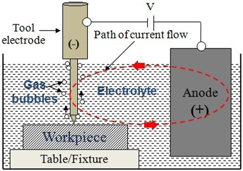
Flow of current in deeply immersed tool-electrode.
Machining system of ECSM
ECSM process covers a long journey, but commercial applications are limited because there is no acceptable machine/machining system developed. In other words, ECSM process is still in the laboratory stage and researchers have developed their own experimental setup to analyze the performance and behaviors of the process parameters. Generally, the ECSM setup consists of machining chamber, power supply, electrolyte supply, electrodes (anode and cathode), gap control mechanism and monitoring system as shown in Figure 5. The photographic view of actual experimental setup is shown in Figure 6. 60
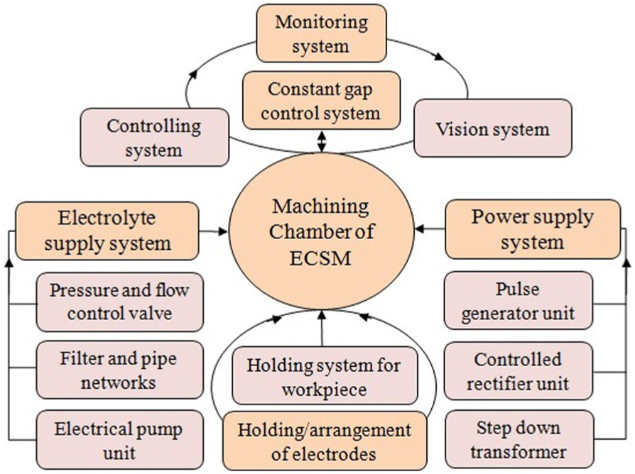
Machining system of ECSM process.
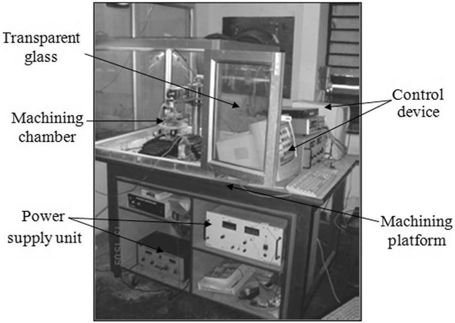
Photographic view of ECSM setup. 60
The machining chamber is a hollow rectangular section made of transparent glass. It is mounted on a suitable platform with appropriate clamping arrangement. The machining chamber consists of electrolyte, workpiece, vice and gap control device. Due to chemically reactive nature of the electrolyte, it is made of non-corrosive material such as glass. Inside the chamber, two electrodes (anode and cathode) are placed away (approx. 25–50 mm) from each other. The workpiece is kept just below (approx. 2–3 mm) from the upper layer of the electrolyte. The tool-electrode (cathode) with a sharp edge (pointed shape) kept near the workpiece and the IEG between tool-electrode and cathode is kept as 20–25 µm.49,50 The machining chamber is housed with X, Y movement for workpiece and Z movement for tool-electrode, which are controlled by computerized monitoring system. To remove fume gases generated during sparks, a well-designed exhaust system has been provided near the machining chamber. The exhaust system consists of electrical exhaust fan and a proper duct/pipe network system to remove exhaust/fume gases from the machining cabin/room.
Power supply unit is an important part of ECSM machining system. Generally, controlled DC power supplies (pulse/continuous) of different ratings are used during machining. First, the main alternating current (AC) (220 V) power supply has been converted into DC power supply by step down transformer and silicon-controlled rectifier unit. Mostly, pulse current is used to increase the performances of the process. Sometimes, a separate power supply unit is used which consists of stepper motors, electrolyte supply, control circuits and monitoring devices.
Electrolyte supply system is used to supply and control the level of electrolyte fluid in the machining chamber. It consists of electrolyte tank, pump, pressure gauge, flow control valve, settling tank and network of pipe lines. The electrolyte (solution of NaOH, KOH, NaCl, H2SO4 or HCl, etc.) fluid is supplied into the machining chamber from electrolyte tank by electrical pump at low velocity because higher velocity means unstable sparks generation resulting in poor performance of the process. After that, the electrolyte of the machining chamber is sent to the settling tank and filtered to remove contaminated materials. Furthermore, a fresh electrolyte is supplied to the chamber for maintaining a constant level into the machining chamber. Sometimes, the electrolyte is injected through nozzle near the tip of tool-electrode or sparking zone for easy removal of molten material from the workpiece surface.
Electrodes (anode and cathode) are used in ECSM process to carry out chemical reaction for gas generation and to create sparks at interface of tool-electrolyte in the presence of gaseous environment. Generally, two types of electrodes, that is, anode and cathode, are used in this process. The anode is made of graphite and plays a role in chemical reaction while the other electrode, that is, cathode commonly known as tool-electrode, is made of copper, brass, stainless steel, nickel, tungsten or platinum.4,15 It is needle/point shaped and is a good conductor of electricity, heat and non-corrosive in nature. These two electrodes are placed in machining chamber away (approx. 25–50 mm) from each other. The tip of tool-electrode is adjusted in such a way that the tip just touches the top surface of the electrolyte fluid because highly immersed tool-electrode is unable to perform spark activities.
Gap control mechanism is used to maintain a constant gap (approx. 20–25 µm) between tool-electrode and workpiece during machining. In general, the feed is always given to the workpiece toward tool-electrode to maintain a constant gap because sparks are only generated near the top surface of the workpiece. In this situation, feed of tool-electrode toward workpiece leads to no-spark formation in deeply immersed condition of tool-electrode into electrolyte. Therefore, to maintain a constant gap, gravity control device is found to be more appropriate and widely used by researchers.23,55,61–63 Several other gap control devices were used by researchers like constant speed mechanism, 45 screw mechanism 51 and stick-slip actuators. 61 A voice coil-type actuator was also used to control the gap between the tool-electrode and workpiece by Ziki et al. 64
The monitoring system is used to precisely position and align the tool-electrode and workpiece in the machining chamber. Typically, highly sophisticated device such as charge coupled device (CCD) camera, optical sensor or computer control device is applied for these purposes. The monitoring devices are mounted near the junction of tool-tip and workpiece with a provision to easily observe the display of the monitor. A graphical user interface–type control and monitoring device was developed by Mediliyegedara et al. 65 They used DC motor as an actuator while ball screws (two numbers) were used to convert rotary motion into linear motion. The linear encoder was used to find the feedback of tool–workpiece position, and servo amplifier (1 µm resolution) was used to control the gap between the workpiece and tool.
Variants of ECSM process
ECSM can be developed to perform as micro-machining process for shaping of electrically non-conductive materials, but it is applied for machining of conductive materials too. It shows their potential to perform several specific operations such as sinking, drilling, milling, cutting, turning and grinding by changing the tool-electrode geometry, conditions and application methods. Nowadays, many different variants such as drilling ECSM, sinking ECSM, milling ECSM, turning ECSM, TW ECSM and grinding ECSM are developed. The different variants of the ECSM are shown in Figure 7 and the descriptions related to variants have been described in brief.
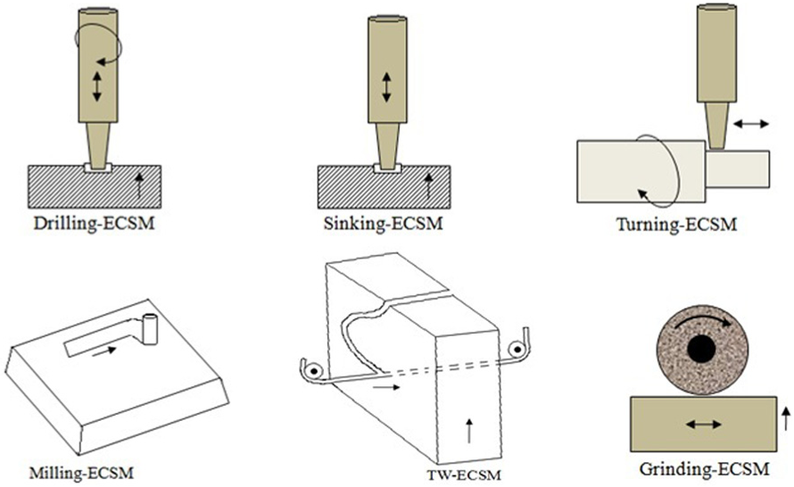
Variants of ECSM process.
Drilling ECSM
Drilling ECSM is the first configuration of ECSM process and was proposed by Kurafuji and Suda 16 during micro-hole drilling into glass workpiece. It is used to fulfill the requirements of the micro-components made of non-conductive (electrically) materials especially ceramic and glass. It is used to produce prototype micro-devices made of fused silica with higher aspect ratio, crack-free surface and SQ near the polished surface.66,67 Jui et al. 67 achieved high aspect ratio (1:11) during drilling (micro-level) of glass with tungsten tool-electrode of 25 µm diameter. They also observed that rotating tool-electrode gives better performances in terms of improvement in circularity without affecting the critical voltage and current. It can be used in different configurations such as through-hole drilling, blind hole drilling, counter drilling and percussion drilling. In drilling, flushing capability is highly affected by peripheral velocity of drilling tool resulting in enhancement in machinability with higher material removal with better SQ.55,68 Instead of this, the rotational speed of the tool leads to a reduction in stray corrosion resulting in improvement in the circularity of drilled hole. Generally, low rotational speed is better for higher material removal with good surface finish and vice versa at higher speed. Gautam and Jain 68 observed two distinct types of the effects of tool rotation in the ECSM process, that is, machinability increases at lower speed (>25 r/min) and decreases with higher rotational speed (<25 r/min) due to instability of the gas film.
In drilling ECSM, the shape of tool-electrode tip is highly affected by the micro-drilling process. Yang et al. 69 claimed that flat surface cylindrical tool gives poor performances than the curve surface spherical tool-electrode. The basic reason behind this is that the curve surface tool-electrode reduces the contact area between the tool and the workpiece and also provides an additional space for the flow of electrolyte. As a result, rapid gas formation and micro-drilling process become highly efficient. The spark formations and drilled holes made by cylindrical and spherical tools are shown in Figure 8(a) and (b) respectively. Zhang et al. 70 analyzed the role of tube electrode in drilling ECSM and they experimentally proved that double-hole tube tool-electrode gives better performances as compared to the solid and single-hole tube electrodes.
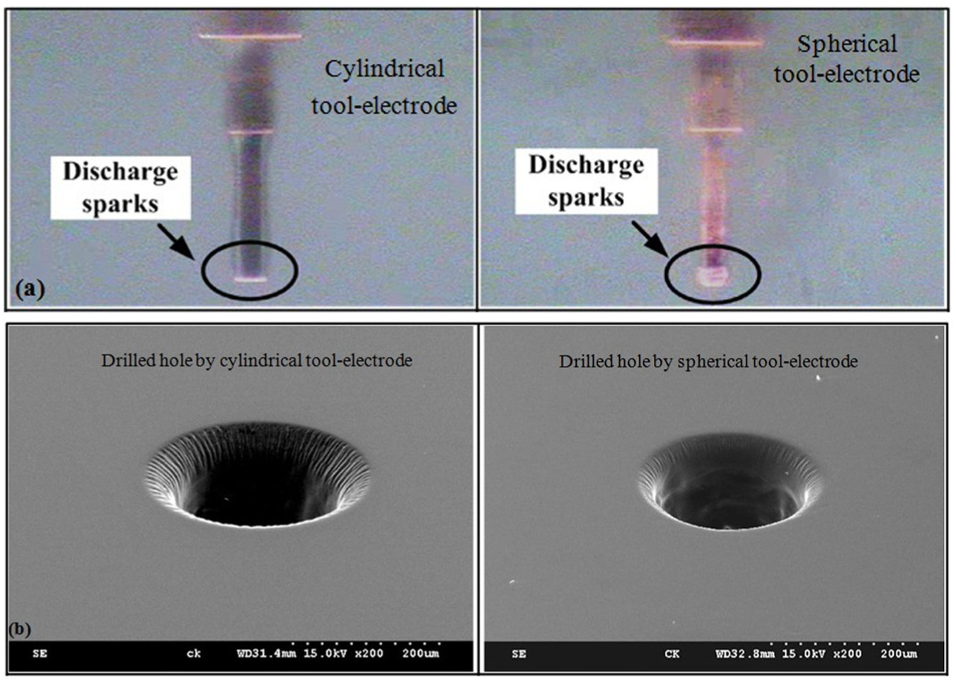
Different shapes of tool-electrodes and drilled holes: 70 (a) spark formation by cylindrical and spherical tool-electrodes, respectively, and (b) drilled holes by cylindrical and spherical tool-electrodes, respectively.
Drilling ECSM process is widely used for micro-drilling of the non-conductive materials, but recently researchers tested the performances for the drilling of conductive materials too. Coteata et al. 71 tested the ECSM process for micro-drilling of stainless steel workpiece in the presence of water as an electrolyte and found satisfactory machining rate. They claimed that the supply voltage has highly influenced the tool wear rate (TWR) followed by rotational speed of the tool-electrode. In drilling ECSM, thin gas film is preferred for better repeatability. Even though, surfactant (liquid soap) was added by researchers in electrolyte which lowers the energy required for intermittent discharge, resulting in reliable results. Dong et al. 72 tested the performances of drilling ECSM during machining of beryllium copper alloys and identified that EDM process is responsible for material removal while the function of ECM process is to enlarge the gap between the tool-electrode and hole. Tandon et al. 73 experimentally investigated the role of ECSM process in cutting and drilling of fiber composites (Kevlar fiber–epoxy and glass fiber–epoxy) with copper tool-electrode in the presence of electrolyte fluid such as NaCl. They concluded that ECSM is a good process for the machining of fiber composites than conventional methods.
The roles of sodium dodecyl sulfate (CH3(CH2)11OSO3Na) surfactant–added electrolyte during drilling ECSM of the quartz material were studied by Laio et al. 74 They investigated that more stable sparks were generated at higher current density and covered larger area as compared to the non-surfactant-added electrolyte resulting in less taper in hole with better SQ. Coteata et al. 75 analyzed the effect of passivating electrolyte in drilling ECSM for sintered carbide workpiece using cylindrical tool-electrodes of diameter 0.50–1.0 mm. They investigated that the electrolyte solution made of sodium silicate behaves like a passivating electrolyte and the tool-electrode always pressed on workpiece surface to split and eliminate the passivating electrolyte through which precision/micro-drilling can be achieved.
Trepanning drilling ECSM process shows their potential to make deep and large-size hole in hard and brittle non-conductive materials economically by providing orbital motion of smaller diameter rotating tool-electrode used in drilling ECSM process.14,76,77 In this method, the orbital motion of the tool-electrode has been achieved by off-setting the tool axis from the spindle axis. 14 The performance of trepanning drilling ECSM is better as compared to drilling ECSM in terms of material removal and other performance parameters. This process becomes beneficial for the machining of complex external and internal profiles such as gear profiles. The roles of abrasive-based drilling tool in trepanning drilling ECSM were analyzed by Sanjay et al. 14 They used abrasive-based tool-electrode (diameter = 1.5 mm) for making large-diameter hole in ceramic material. They claimed that abrasive-based tool shows higher machinability (material removal and SQ) as compared to without abrasive drilling tool used in drilling ECSM process under same conditions.
Sinking ECSM
Sinking ECSM process can be used to create micro-holes in the workpiece with application of stationary tool-electrode (reciprocating type) for manufacturing of molds and dies.18,75 Generally, sinking ECSM process has been used for making of through- and blind micro-holes in the workpiece to achieve higher aspect ratio. It also shows their potential to make small and shallow (ultra-precision) features for nozzles, orifices, dies and molds made of non-conductive, semi-conductive or conductive materials. It becomes a better replacement of the EDM process to remove broken taps, drill bits, bolts or rivets from highly multifarious complicated parts.
Generally, the tool-electrodes for sinking ECSM are made of copper or brass due to ease in formability, chemically non-reactive and easy availability. It may be of different cross sections such as square, rectangular, triangular, hexagonal or any complex profiles. Khairy and McGeough 17 claimed that hollow tool-electrode gives better performances as compared to solid tool-electrode. The process capability of sinking ECSM in terms of material removal is higher than constituent processes (ECM and EDM), but dimensional accuracy is near to EDM and better than ECM processes. Similar observations were concluded by Bhondwe et al. 34 They reported that material removal of the ECSM process has been closer to EDM and lower than ECM processes. Mediliyegedara et al. 24 applied sinking ECSM process for machining of mild steel workpiece with copper tool-electrode in the presence of NaNO3 electrolyte and finally developed an artificial neural network (ANN) model due to complexity in the process. Panda and Yadava 78 also analyzed the performances of sinking ECSM process using Artificial Intelligent (AI) model and optimized the process parameters using gray relational analysis (GRA) technique.
The application of FEM has also been tested by several researchers to investigate the outcomes of control factors on the response parameters. Bhondwe et al. 34 analyzed material removal for soda lime glass and alumina workpieces considering single spark for their FEM-based analysis. They found improvement in material removal with increase in concentration of electrolyte, energy partition and duty factor. Gadalla et al. 79 developed FEM model for analysis of spark diameter. They determined the average diameter of plasma as 260 µm during machining of glass material. They also verified the theoretical results in terms of material removal and crater depth with experimental observations and found that theoretical results were well fitted with experimental values.
Turning ECSM
Turning ECSM is a recently developed configuration of ECSM process to machine the axisymmetric parts of circular cross sections. Generally, turning operation is performed on lathe machine to remove undesired material from rotating workpiece surfaces. Such concept of machining has been introduced as turning ECSM process to machine circular non-conductive materials. The rotational speed of the workpiece assists the supply of fresh electrolyte into the gap between the workpiece and tool-electrode resulting in higher material removal and reduction in the surface cracks. 80 Instead of this, the feeding mechanism for workpiece during turning ECSM is not required resulting in reduction in the complexity. This process becomes beneficial for turning of different profilers such as cylindrical turning, taper turning, step turning and thread turning operations.
Only limited numbers of published article are available on turning ECSM process. Furutani and Arai 80 tested the performance of turning ECSM during machining of glass with thin diameter of tool-electrode in the presence of sodium silicate electrolyte fluid. They analyzed the different cutting forces related to turning, which were measured by two-axis sensor-type force measuring instrument. They also claimed that the dissolution of sodium silicate causes material removal. A similar explanation was given by Furutani and Kojima. 81 They claimed that heat generated during the discharge accelerates the chemical reactions through which a bit of workpiece material detached resulting in material removal. They analyzed the effect of turning ECSM process during machining of silica glass in the presence of the NaCl (20%) electrolyte solution. They used tungsten wire (diameter = 0.30 mm) as the tool-electrode during turning ECSM process. They also agreed that spalling of material from the grain boundaries during electrical discharge causes material removal in turning ECSM process.
Milling ECSM
Milling ECSM process shows their potential to create three-dimensional (3D) micro structures, cavities and profiles on the surface of non-conductive materials by adopting the strategy of tool-electrode movement similar to conventional milling. Several researchers applied milling ECSM to create 3D micro-profiles such as micro-channels and micro-grooves on the ceramic workpiece surfaces. Lee et al. 52 created 3D micro-fluidic system and connected to standard plastic pipes. They experimentally found that such connections withstand a pressure of up to 30 psi without leakage/failure. Langen et al. 82 created 3D profiles in glass ceramic using an orbital motion of tool-electrode during milling ECSM. Viswanadh and Yadava 83 suggested that the use of converged section of the nozzle for supplying the electrolyte in desired quantity at machining area leads to better spark generation.
Layer-by-layer material removal also shows higher potential as compared to moving tool-electrode in milling ECSM process. Zheng et al. 84 experimentally machined 3D micro groves of 100 and 350 µm using layer-by-layer technique in milling ECSM of Pyrex glass. In this technique, they used small machining depth of 50 µm and travel rate of tool-electrode of 1000 µm/min for machining of micro-groves. Cao et al. 85 experimentally created micro features less than 100 µm at glass surface and claimed that milling ECSM shows their potential for micro-grooving, micro-pillars and micro-pyramid like complex profiles. Paul and Hiremath 86 formed micro-channel by this process. Mallick et al. 87 also formed micro-channel in glass workpiece and investigated the outcomes of control variable on material removal, surface roughness and overcut in the presence of NaOH electrolyte with stainless steel tool (diameter = 350 µm). They analyzed that discharge voltage of 55 V and concentration of electrolyte of 30% wt give higher material removal as compared to their other combinations.
The sequential operation of the micro-EDM and micro-ECM in the place of simultaneous application for 3D profiles has been tested by Zeng et al. 88 They claimed that surface roughness of micro-grooves has been lowered from 0.707 to 0.143 µm when micro-ECM process has been applied after micro-EDM in profile milling of the metallic workpiece. This is because recast layer and surface defects formed during micro-EDM are completely removed during micro-ECM process. They also show that the combination (micro-EDM and micro-ECM in milling) is a powerful approach for creating 3D metallic micro-structure but they did not compare the sequential process with milling ECSM (simultaneous) process.
TW ECSM
TW or moving wire ECSM is a widely acceptable machining process and is simply known as TW ECSM process. In TW ECSM, the stationary/rotating tool-electrode of sinking/drilling ECSM has been replaced by moving wire. Generally, the diameter of moving wire (tool-electrode) is less than 1 mm and the rotating speed is also very less as few centimeters per minute. 22 It is widely applicable for shaping of complex profile in non-conductive materials with application of movable wire (tool-electrode) on any surfaces (internal or external) for micro-cutting such as gear cutting, comb profiles, chutes or channels. The performance of TW ECSM in terms of material removal is much higher (5 and 50 times) as compared to EDM and ECM, respectively. 22
In TW ECSM, the spark is generated between moving wire made of copper, brass or tungsten and at the surface of workpiece as a result of melting, vaporization and erosion of workpiece material.89,90 Generally, different types of feed mechanisms were used by researchers to maintain a constant gap between moving wire and workpiece such as ball screw and slide mechanism,37,89 dead weight mechanism 91 or gravity. 51 Flushing methods such as jet or nozzle are not required during TW ECSM because the moving velocity of the TW enhances the flushing efficiency. The reciprocal motion (to and fro) across the moving wire facilitates flushing as a result of easy removal of debris from the gap and improvement in machinability. 91 The feed rate and wire velocity are the most significant parameters of TW ECSM process. Higher feed rate leads to accumulation of debris and inefficient flushing while higher wire velocity leads to disturbance in spark formation (unstable spark) through which there is declination in the performances of the process. Kuo et al. 27 experimentally investigated that feed rate up to 350 µm/min was much better during machining of quartz glass as compared to higher feed rate due to continuous disturbance in gas film formation near the moving wire. Kerf width is also affected by wire velocity and higher wire velocity is responsible for higher kerf width. Bhuyan and Yadava 37 investigated that lower wire velocity was much better as compared to higher wire velocity during TW ECSM of borosilicate glass. They also indentified that the combinations of the process parameters such as wire velocity and pulse duration of 1.8 m/min and 300 µs, respectively, give lower kerf width with higher material removal as compared to wire velocity and pulse duration of 3.0 m/min and 500 µs, respectively.
Grinding ECSM
Grinding ECSM is an implementation of mechanical grinding in ECSM process, where rotating metallic wheel (without abrasives) has been applied to create spark at the surface of the workpiece in the presence of hydrogen gas bubbles. The removal of material occurs due to etching, melting and vaporization. The nature of machining is almost similar to grinding and the process is known as grinding ECSM. There is no need of direct flushing because the peripheral velocity of the wheel enhances the flushing efficiency of the process. 92 Thus, higher velocity is always beneficial for improvements in flushing but simultaneously leads to a decrease in spark phenomenon due to continuous damaging of hydrogen gas bubbles near the peripheral surface of the grinding wheel. Such a phenomenon leads to lower material removal rate (MRR) with poor SQ.
To improve the machinability of grinding ECSM process, the application of the metal-bonded abrasive grinding (AG) wheel has been found to be a better option, but only very few researchers focused in that direction. Jain et al. 33 tested the performances of conical and cylindrical abrasive–based tool in ECSM during machining of alumina and glass. They experimentally verified that abrasive-based tool-electrode gives better performances in terms of enhancement in material removal and machining depth as compared to conventional cutting (without abrasive) wheel (tool-electrode). Liu et al. 93 tested the performances of grinding ECSM during machining of metal matrix composites and found improvement in the machinability of the process. The alternative applications of the micro-grinding in ECSM during machining of glass with diamond wheel were tested by Cao et al. 94 They experimentally identified that surface roughness of ECSM machined workpiece was reduced up to 0.05 µm with machining time much lower than conventional grinding.
Process and performance measures
ECSM is a complex combined unconventional process that comprises the features of two machining processes, that is, ECM and EDM, for shaping of the electrically conductive and non-conductive materials. Therefore, a lot of factors related to the constituent processes (ECM and EDM) are affected by the performances of ECSM process. These parameters may be controllable or non-controllable which directly or indirectly affect the performances of the process. The controllable parameters (current, voltage, pulse interval, pulse duration, concentration, etc.) are easily controlled while uncontrolled parameters (humidity, temperature, working environment, machine efficiency, etc.) are difficult to be controlled by operator during machining. Neglecting the non-controllable parameters, the process (controllable) and performance parameters related to ECSM are shown in Figure 9.
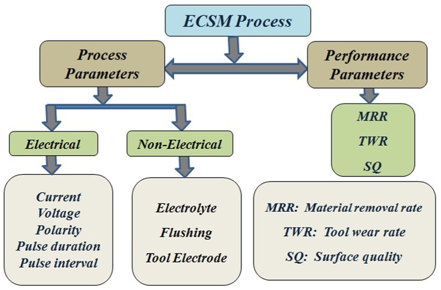
Process and performance parameters of ECSM process.
Process parameters
The process parameters related to ECSM can be categorized into two different groups such as electrical (power supply) and non-electrical (electrolyte, concentration, flushing and tool-electrode, etc.) parameters.
Electrical parameters
The major electrical parameters related to power supply are current density, discharge voltage, pulse duration, pulse interval, frequency and polarity. The pulse current is not a much significant process parameter that affects the performances, and only very few researchers considered it as an important parameter during machining.26,70 Generally, DC current is applied in either continuous or pulse (wave) form in machining. 15 Even though the pulse form of current gives better responses as compared to continuous supply. In ECSM process, lower value of current (approx. 1 A) has been applied to get desired machinability. 47 The value of current increases until it reaches the preset value during each spark. Higher value of current leads to poor SQ with higher material removal capacity during machining.
Applied voltage is the most significant parameter and it is related to the gap between the workpiece and tool-electrode. It increases till the ionization path has not been created between the tool-electrode and workpiece. Higher applied voltage increases the gap resulting in improvement in flushing efficiency and easily removal of the debris from the gap. During analysis of applied voltage, the hole diameter shows decreasing trends with an increase in applied voltage. 26 The values of optimum voltage for drilling of quartz with tool made of stainless steel, tungsten carbide and tungsten of 38, 40 and 41 V, respectively, were identified by Yang et al. 26 Even though the diameter of the holes increases with an increase in voltage after optimum value. Bhuyan and Yadava 37 found that material removal and kerf width are directly related to voltage, and increases in discharge voltage mean an increase in performance measures. SQ is also affected by discharge voltage, and lower discharge voltage is much suitable for better SQ. Ali and Reza 95 observed that higher discharge voltage is not beneficial for ECSM process and it leads to higher tool wear.
Pulse duration or pulse on-time is the most important parameter of ECSM machining process, and most of the basic phenomena of the ECSM process depend on pulse duration (pulse on-time) such as plasma formation, heat generation, melting and vaporization. Longer pulse duration is responsible for same heat sink to workpiece materials for a longer time as a result of higher melting of material and their removal. 37 Longer pulse duration is not always beneficial and increases the pulse duration after optimum value leading to declination of response parameters including formation of the recast layer and deep cavity on the workpiece surface through which roughness value increases with lower capability of material removal.
Pulse interval or pulse off-time mainly affects the flushing and machining rate resulting in improvement in machinability. Generally, higher value of pulse interval leads to longer time for flushing resulting in complete ejection of the molten material from workpiece surface. Due to this, there is reduction in the roughness value and kerf width. 37 Even though much longer pulse interval is not preferred due to reduction in material removal and formation of comparatively harder surfaces. In a similar way, smaller pulse interval leads to faster machining rate with good SQ, but much shorter interval time means insufficient ejection of the melted material and as a result short circuiting occurs.
Polarity is also highly affected by the performances of ECSM and it may direct or reverse depending on the connection of the tool-electrode and workpiece. In ECSM, the tool-electrode is connected to the cathode (−ve) and dummy electrode (graphite) is connected to the anode (+ve) terminals. Such a connection is known as direct polarity. On the other hand, tool-electrode is connected to the anode (+ e) and such a combination is known as reverse polarity. 35 The polarity plays a significant role in machining and decides after pilot experimentations. Jain and Adhikary 35 experimentally investigated that reverse polarity gives higher material removal with rougher surface than direct polarity during ECSM of quartz. They further investigated that direct polarity leads to crack formation on the machined surface while no such crack has been found on the machined surface obtained with reverse polarity as shown in Figure 10(a) and (b). This phenomenon shows that chemical etching occurs during ECSM process with reverse polarity being more effective than direct polarity. 35
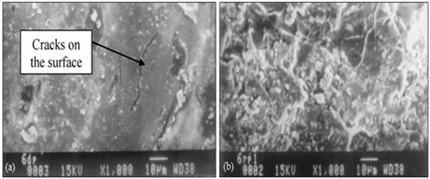
Machined surface by different polarities (V = 80 and concentration = 16% wt): 35 (a) ECSM with direct polarity and (b) ECSM with reverse polarity.
Non-electrical parameters
The non-electrical parameters such as electrolyte, flushing and tool-electrode are highly influencing process parameters and play an important role as electrical parameters during ECSM process. The electrolyte parameters affected by the performances of ECSM are electrolyte materials, pressure, temperature, concentration and way of application in the machining zone. Generally, electrolytes are chemically reactive and hazardous in nature. The most commonly used electrolyte fluids are KOH, NaOH, NaCl and NaNO3.45,47 Instead of this, several acid-based electrolytes such as HCl and H2SO4 are also used in ECSM process. The concentration of the NaOH electrolyte as 30% has been preferred as compared to others. 4 Even though 25% concentration of NaOH was found to be better for machining of borosilicate glass at temperature ranges of 20 °C–40 °C by Bhuyan and Yadava. 37 In general, the temperature range of electrolyte of 40 °C–50 °C is much better for ECSM process. 4 Mallick et al. 87 claimed that 30% electrolyte concentration was much better for micro-cutting of glass. The purposes of electrolyte during ECSM process are to generate hydrogen gases as well as removal of debris particles from the gap between tool-electrode and workpiece. Therefore, the electrolytes are supplied in the cutting zone in such a way that the workpiece and tool-electrode are immersed into them and no turbulence is created near the workpiece–tool surfaces. Generally, jet/nozzle flushing is applied in sinking/drilling ECSM. Even though the flushing direction of electrolyte fluid either perpendicular or coaxial of moving wire has been applied during TW ECSM process.
Research works also focus on the role of tool-electrode and related significant parameters especially materials and geometry. Generally, highly electrically and thermally conductive and chemically non-corrosive materials such as copper, brass, stainless steel, nickel, tungsten or platinum are used as tool materials.4,15 Yang et al. 26 experimentally investigated that tungsten carbide tool-electrode shows better machinability as compared to tungsten and stainless steel tool-electrodes but it suffers from higher tool wear during ECSM of the quartz workpiece. The comparison between different tool-tips such as spherical and cylindrical was made by Yang et al. 69 They investigated that curve surface as spherical tool leads to an increase in flushing resulting in better machining performance as compared to the cylindrical tool-electrode. The role of tube electrode was investigated by Zhang et al. 70 They investigated that tube electrode gives better performances as compared to solid tool-electrode in terms of higher material removal and lower taper in hole profiles. Zheng et al. 96 investigated that tool geometry is also responsible for machining during micro-drilling ECSM of Pyrex glass.
Performance parameters
The widely accepted performance parameters are MRR, TWR and SQ. Generally, MRR and TWR can be determined by dividing the loss in mass with duration of machining while SQ reflects the surface roughness and is directly measured using surface measuring instrument. Most of the time, MRR and TWR increase with increases in control parameters such as applied voltage, pulse duration, pulse interval and concentration up to certain values. The peripheral velocity of tool-electrode enhances material removal and surface finish.19,67,97 In a similar way, the velocity of moving wire in TW ECSM process also enhances the machining performances up to 22.7% in terms of material removal. Even though increments in abnormal arcing were observed during machining of conductive materials resulting in deterioration of machining characteristics. 5 The tool geometries also affected material removal and SQ. 96 Jain et al. 33 claimed that abrasive-based tool-electrode gives higher MRR and depth of cut with good SQ as compared to conventional (without abrasives) tool-electrode. Zhang et al. 70 investigated that multi-tube electrode gives higher MRR as compared to single-hole tool-electrode with smaller taper values. Polarity also affected the SQ, and reverse polarity is not beneficial as compared to direct polarity for the better SQ. 35
In addition, other response parameters such as heat-affected zone (HAZ), radial over cut (ROC), taper in hole and forces were also analyzed by several researchers. Jui et al. 67 investigated that higher aspect ratio (1:11) has been possible with lower concentration of electrolyte during micro-drilling into glass workpiece. They showed that lower concentration also reduces the ROC by 22% and hole taper by 18% positively. Zhang et al. 70 investigated the role of solid and hollow tool-electrode in ECSM process and claimed that hollow tool-electrode gives smaller taper as compared to solid tool-electrode, which is followed by multi-hole-based tool-electrode. Mallick et al. 87 experimentally identified that HAZ decreases with frequency and increases with duty factor to 50%–55% in the presence of NaOH electrolyte with cylindrical-shaped tool made of stainless steel. Sarkar et al. 97 analyzed the roles of applied voltage, concentration and IEG on MRR, ROC and HAZ during ECDM of silicon nitride. Hajian et al. 98 analyzed the effect of process parameters such as tool diameter, concentration, magnetic field and feed rate on the tool-electrode during milling ECSM of the glass. They investigated that magnetic force significantly reduces the forces acting upon the tool-electrode in the presence of low concentration (15% of weight) of the electrolyte during milling ECSM process.
Hybridized ECSM processes
ECSM is a well-known hybrid machining process that comprises two different forms of energies, that is, thermal and chemical, to eliminate the drawbacks of EDM and ECM processes. It becomes an advanced/unconventional machining process for shaping of conductive and non-conductive materials. Even though it suffers from several inherent problems such as continuous arcing during machining of conductive materials and formation of recast layer which requires further machining. Therefore, to enhance the performances of ECSM process and to minimize/eliminate the drawbacks, the researchers combined or hybridized ECSM process with other machining processes. Such combined processes are called as hybridized ECSM or ECSM-based hybrid machining processes. The purposes of the hybridization of ECSM with different machining processes are to utilize the potential merits and at the same time dismiss the demerits of the constituent processes as a result enhancement in the machinability of the hybridized ECSM processes.
Classification of hybridized ECSM processes
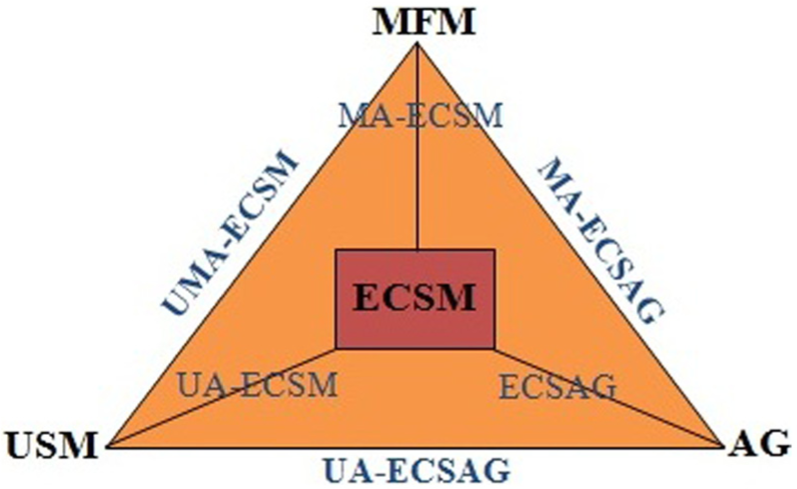
Recently, researchers considered ECSM as single machining process and defined as non-traditional machining process for shaping of conductive and non-conductive materials in the ranges of micro (1–999 µm) level. Even though it is still in the laboratory stage and not commercialized till now. Furthermore, no appropriate classification of the ECSM process has been found within available resources. The hybridization of ECSM with other machining processes is named as triplex-based hybrid ECSM processes by Singh and Dvivedi. 76 In this section, the hybridized ECSM processes are classified either based on energies or based on the involvement of constituent processes in the machining. On the basis of energy sources, the mechanical or magnetic force is used for hybridization of ECSM process. The mechanical energy–based hybridized ECSM processes are ultrasonic-assisted sinking ECSM (UAS ECSM), ultrasonic-assisted drilling ECSM (UAD ECSM), electro-chemical spark abrasive grinding (ECSAG), ultrasonic-assisted ECSAG (UA ECSAG) and so on, while magnetic energy–based ECSM processes are magnetic force–assisted ECSM (MA ECSM), magnetic force–assisted abrasive grinding ECSM (MAG ECSM) and ultrasonic magnetic force–assisted abrasive grinding ECSM (UMAG ECSM).
Furthermore, the combined machining processes with ECSM may be directly or indirectly involved to raise the machinability of hybridized processes. Therefore, based on involvements, the hybridized ECSM can be classified as associated and assisted type hybridized ECSM. In associated hybridized ECSM processes, all the constituent processes directly involve to improve the machinability and continuously make their efforts toward that direction such as ECSAG, UA ECSAG, MA ECSAG, and powder-mixed (PM) ECSAG. On the other hand, the constituent processes are not directly involved in improving the machinability, and among them only one process is directly involved in machining, while other processes facilitate or assist the machining method known as assisted type hybridized ECSM processes such as UAS ECSM, UAD ECSM and MA ECSM. The general classification of the hybridized ECSM process is shown in Figure 11.
Classification of hybridized ECSM process.
ECSAG
ECSAG is a cooperative type hybridized ECSM process. In this process, the material removal occurs due to chemical dissolution, spark erosion and abrasive abrasion, that is, three different energies such as chemical, thermal and mechanical are responsible for material removal as shown in Figure 12. To implement the abrasion action of grinding ECSM process, a metallic wheel with abrasive (metal bonded) aided has been applied during machining and the process becomes as ECSAG. Spark phenomenon occurs between bond material (metallic part) and gas bubbles (Figure 12) due to which the workpiece material melted and vaporized. Simultaneously, abrasive particles make contact with workpiece surface and soften material removed due to abrasion action of abrasive particles. Due to the application of grinding wheel, ECSAG process can be developed in different configurations such as cut-off ECSAG, surface ECSAG and face ECSAG. The cut-off ECSAG and surface ECSAG use peripheral surface of abrasive (grinding) wheel and the wheel rotates their horizontal axis, while face surface of the wheel is used in face ECSAG for machining of desired workpieces and the wheel rotates their vertical axis. The basic purposes of AG in ECSM are to improve the productivity (material removal and SQ) and simultaneously reduce the white (recast) layer and micro-cracks on machined surfaces.
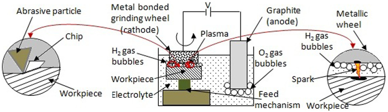
Details of ECSAG process.
In the area of ECSAG, only limited researchers focused on machining of non-conductive materials. Liu et al. 93 tested AG with ECSM process to improve the performances for machining of Al/AlO composite with diamond abrasive (DA)–based grinding wheel. They claimed that AG significantly removed the recast layers on the machined surface. They also experimentally showed that ECSAG process gives better SQ (approx. 10 times) with higher (approx. 3 times) material removal as compared to ECSM process. Kumar and Yadava 99 developed a setup of ECSAG in the face grinding mode and studied the performances of developed setup on glass fiber epoxy with metal-bonded diamond wheel. They experimentally observed that ECSAG gives higher (30%–60%) material removal and better (20%–40%) SQ as compared to ECSM process. Instead of simultaneous application of electrical discharge (spark) and abrasive abrasion, the alternative effect of electrical spark and abrasion in the ECSAG process was analyzed by Cao et al. 94 They applied micro-grinding after ECSM of the glass and found the potential of grinding process to remove the recast layer effectively resulting in better SQ (approx. 10th times) compared to the ECSM machined surface.
PM ECSM
In PM ECSM, loose conductive particles are mixed with electrolyte to improve the surface integrity of ECSM process. 100 Generally, the generation of fine spark with uniform energy and their fine control are highly desired to get higher machinability and surface finish. Such types of studies during machining of borosilicate glass were analyzed by Han et al. 100 They studied the roles of graphite particles during PM ECSM for borosilicate workpiece material. They experimentally investigated improvement in surface roughness as 4.86–1.44 µm with mixing of graphite particles of average diameter size of 10 µm into NaOH electrolyte. The basic reason behind this is reduction in direct impact of the spark energy on workpiece surface due to the presence of abrasive particles in gas films and effects during PM ECSM process. They also observed that micro-cracks were significantly reduced with mixing of 1.0 wt% of graphite powder concentration in 30% NaOH of electrolyte.
The application of abrasive-based conductive particles shows their potential over normal conductive particles in PM ECSM due to their abrasive nature. Due to the presence of loose abrasive particles in electrolyte, a lot of particles make contact with workpiece surface freely resulting in small amount of material being removed from workpiece surface. This phenomenon leads to improve the SQ and help to achieve the SQ up to micro/nano level. The abrasion action of abrasive particles also minimized/removed the micro-cracks on the machined surface. 100 The roles of abrasive-based PM ECSM were tested by Yang et al. 91 They analyzed the roles of SiC abrasives in PM wire ECSM process. They observed that concentration of abrasive particles in the gap disturbs the formation of hydrogen gases, and as a result higher critical voltage is required resulting in enhancement in material removal at higher supply voltage. They also found that surface roughness improves with mixing of abrasive particles in electrolyte due to the removal of micro-crack and HAZ formed during electrical discharge. They also found that surface roughness increases 1.20–1.80 µm with an increase in the abrasive particles from 11 to 20 µm, respectively.
Electro-chemical spark abrasive drilling
Electro-chemical spark abrasive drilling (ECSAD) is the implementation of abrasive-based tool-electrode in drilling ECSM process. In this process, three different energies such as chemical, electrical and mechanical are used to perform chemical dissolution, spark erosion and abrasive abrasion phenomena.33,101 The application of abrasive-based tool-electrode in ECSAD process was tested by Jain et al. 33 They compared the performances of abrasive cutting tool (ACT) with conventional cutting tool (CCT) during machining of borosilicate glass and alumina. They investigated that ACT gives higher material removal as compared to CCT due to roles of abrasion particles in drilling ECSM process. They also investigated that abrasive particles make sufficient gap between the workpiece and bond materials due to effective protrusion heights, and as a result huge amount of bubble are formed during chemical reaction.
The comparative studies between hollow tool-electrode (stationary) and abrasive tool-electrode (rotary) during ECSAD of Al2O3 workpiece were made by Sanjay and Rao. 101 They investigated that material removal decreases with an increase in depth, and after a certain depth, the machining becomes much difficult. This is due to lack/insufficient formation of gas bubbles at higher depth. Even though such phenomenon has been avoided using abrasive-based tool-electrode in drilling ECSM due to protrusion heights of abrasive particles which efficiently raised the formation of gas bubbles. Ladeesh and Manu 102 identified that higher frequency (>4 kHz) leads to micro-cracks on machined surface but simultaneously increases material removal during ECSAD of borosilicate glass. They also suggested that ECSAD is a high-flying emerging technique, which offers high degree of dimensional accuracy during drilling of holes into hard and brittle ceramics.
The role of abrasive-based tool-electrode in trepanning ECSAD for machining of Al2O3 was tested by Sanjay et al. 14 They compared the abrasive tool with copper (without abrasive) tool with DC supply (continuous/pulse). They investigated that DC pulse voltage reduces the tendency of crack formation at higher supply voltage as compared to continuous DC voltage. They also investigated that abrasive tool drilled dipper holes effectively with higher dimensional accuracy than normal (without abrasive) tool-electrode. They also suggested that orbital motion of tool-electrode shows the potential for drilling of larger (diameter) holes into ceramics with applications of smaller diameter of tool-electrode effectively and economically.
Ultrasonic-assisted electro-chemical spark drilling
Ultrasonic-assisted electro-chemical spark drilling (UA ECSD) is an application of mechanical energy in the form of vibration (ultrasonic) in drilling ECSM process. Ultrasonic vibration in ECSM effectively changes the discharge behavior and improves the electrolyte circulation, as a result no accumulation of debris takes place as which stable sparks are generated. Instead of this, the accumulation of discharge heat does not occur and it spreads at the workpiece surface resulting in reduction in micro-crack formation. 103 The purposes of ultrasonic vibration in drilling ECSM are to enhance machining performances such as material removal and SQ of the drilled workpieces by improving the circulation of electrolyte into the gap between tool-electrode and workpiece during machining.
Rusli and Furutani 103 analyzed the behaviors of the UA ECSD during machining of the glass workpieces with tungsten tool-electrode. They identified that higher amplitude of ultrasonic vibration leads to wide and dense pulse current during machining which decreases the material removal capability of the process. They also investigated that high bias current with lower level of electrolyte without ultrasonic vibration is responsible for better SQ with lower value in material removal capability during UA ECSD of the glass workpiece. Even though the machinability of UA ECSD was found to be much better than ECSD process. The ultrasonic vibration is applied to the workpiece or tool-electrode. Elhami and Razfar 104 investigated that the application of ultrasonic vibration to the tool-electrode means that the concentration of vibration is only in the machining zone. They also observed that vibration speeds up the machining discharge and also controls the hydro-dynamic machining process resulting in higher material removal. Instead of this, vibrational amplitude of 10 µm created the most uniform current signal in machining zone resulting in uniform and stable sparks.
UA ECSAG
UA ECSAG is the application of ultrasonic vibration in ECSAG process. The application of ultrasonic vibration in ECSAG process was analyzed by Zhao et al. 105 They tested the vibration in ECSAG process for the in-progress dressing of abrasive (diamond) grinding wheel. They investigated that white (oxide) layer forms on the grinding wheel surface after each electrical discharge. Such oxide formation leads to a decrease in the protrusion heights of the abrasive particles resulting in low material removal and poor SQ. They also investigated that the thickness of oxide layer formation is inversely proportional to ultrasonic vibration (amplitude and frequency). Therefore, the application of ultrasonic vibration in ECSAG is an effective way of in-process dressing method of diamond grinding wheel as which the wheel maintains their cutting ability for a long time, but more research works are required in the same field.
Magnetic field–assisted milling ECSM
Magnetic field–assisted milling ECSM (MAM ECSM) comes into existence to improve the quality of micro slots, grooves, channels and so on made by milling ECSM process. In this process, magnetic force is applied with milling ECSM process with application of a permanent magnet. Hajian et al. 106 developed a set for MAM ECSM process to cut the micro-channel into soda lime glass. For this, a permanent magnet of intensity as 4500G was used. They found improved SQ (0.692 µm) with high depth of cut (300 µm) with MAM ECSM as compared to without magnet milling ECSM with SQ (0.753 µm) and depth of cut (170 µm) at supply voltage of 35 V and electrolyte concentration of 15% wt of NaOH positively. Even though the improvement in material removal at higher concentration was not much significant due to lower viscosity of electrolyte at lower concentration which facilitates the removal of etch particles from the machining zone. The basic advantage of magnetic field in ECSM process is the development of magneto hydro-dynamic (MHD) convection into the gap between the workpiece and tool-electrode in the presence of electrolyte. Due to this, there is effective circulation of electrolyte which facilitates deep hole machining and finally generates better geometry of machined surfaces. Furthermore, magnetic force assists to generate more stable spark and easily breaks of the gas bubbles away from the surface of tool-electrode. As a result, a uniform layer of gaseous zone has been formed surrounding the surface of the tool-electrode which contributes to higher machining rate due to requirement of higher supply voltage in the machining zone. 76
Magnetic field–assisted TW ECSM
In TW ECSM process, the circulation of electrolyte into the gap defers in the close vicinity of the machining zone resulting in decline in material removal. To overcome the above problem, the application of MHD convection in TW ECSM process becomes beneficial. Such studies related to the existence of magnetic field in TW ECSM process were analyzed by Rattan and Mulik. 107 They examined that the MHD convection pushes the electrolyte into the sparking zone (gap between tool-electrode and workpiece), and finally a uniform gaseous environment is obtained surrounding the tool-electrode. Such a phenomenon leads to uniform presence of hydrogen gases resulting in uniform and precise formation of sparks. They also found an improvement of 9.09%–200% under different processing conditions resulting in higher productivity with better surface qualities.
Discussion and future directions of research
This article presents a report on the published article on different configurations of the ECSM and hybridized ECSM processes. After sophisticated analysis of the published works, it has been analyzed that the machining mechanism of ECSM process is a highly complex phenomenon and still in the laboratory stage. Even if the mechanism of material removal of ECSM is still an unknown phenomenon and not fully understood by researchers. In this study, an effort has been made in that direction to clear the spark phenomenon considering arc formation in gas. Several researchers contributed their efforts to eliminate the drawbacks of EDM and ECM processes after combining them in terms of ECSM, which is effectively applicable for machining of conductive and non-conductive materials. The research works show that it is widely used to get the micro features on non-conductive materials and most of the works were done on glass ceramics. Even though the cost-effectiveness requires more research works in the same area.
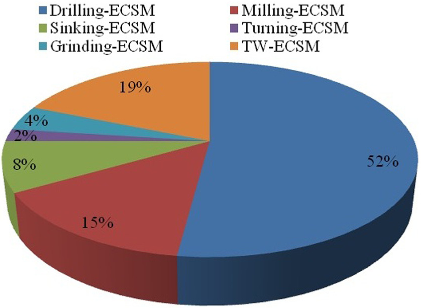
This article focuses on research works published on ECSM and different configurations too. The reviewed work shows that most of the researches are performed on non-conductive materials preferably glass ceramic, and limited research works are conducted on conductive materials such as steel and metal matrix composites. Therefore, such area requires more studies to analyze the performance behaviors of ECSM during machining of advanced engineering materials including heat-treated alloys, super alloys, tool and die steel and so on. The review work shows that most of the research works are carried out in the area of drilling ECSM followed by TW ECSM, milling ECSM, sinking ECSM, grinding ECSM and turning ECSM. 76 Therefore, more research works are required in the same field that provides an ample opportunity to analyze the effects of process parameters on performance measures. The percentage distribution of works carried out in different configurations of ECSM is graphically presented in Figure 13 as reported in the research articles.
Research works carried out in different variants of ECSM.
Among different variants of ECSM, drilling ECSM shows their potential for micro-drilling with high aspect ratio (1:11). 67 Even though trepanning drilling shows their potential for drilling of large-diameter hole with application of smaller diameter of tool-electrode having orbital motion. Limited researchers were focused their works in the same area; as a result, the feasibility of trepanning ECSM is still unexplored and requires more studies in the same field. Instead of drilling/trepanning, sinking ECSM is another way for producing micro-holes, groves or creating impression on the workpiece surface, but limited researchers focus in that direction to create micro/nano holes. Even though creations of replica of the tool-electrode surface on the workpiece surface are still to be studied. Improving machinability in terms of higher material removal, better SQ, smaller tool wear and low-cost machining still requires more studies in the same field.
Milling ECSM process is capable to cut the micro-channels, groves or slots for hydraulic/fluidic application up to micro/nano level. Therefore, an emerging scope of research needs to achieve low-cost machining of micro/nano components in repeating ways. Application of magnetic force in the field of milling ECSM becomes another scope for research to create micro/nano profiles such as micro/nano channels or grooves. Most of the researchers focus on the TW ECSM to cut complex profiles with application of moving wire in place of stationary tool-electrode used in the ECSM process. The mixing of conductive powder into electrolyte enhances the material removal capability with better SQ. 100 Abrasive-based conductive powder performs better as compared to conductive material, but till now only SiC abrasives are tested in the TW ECSM.91,100 Therefore, machinability and suitability of abrasive particles for particular material need to be explored. The grinding ECSM configuration is a unique machining process for rapid machining of the slots, groves, flat or face surfaces. Several different configurations of grinding ECSM can be developed such as face, surface or cut-off grinding. Therefore, a lot of research works need to analyze the process behavior in different configurations of grinding ECSM. The application of ultrasonic vibration in abrasive-based grinding ECSM shows their potential for in-process dressing of abrasive wheel. 105 Such a process can be developed for different configurations of grinding ECSM process and to create a broad field of research. Turning ECSM process is a recently developed new configuration of ECSM and no more research articles are published. It can be developed in different configurations such as step turning, taper turning and face turning and can cover a wide range of ECSM process.
The published research work shows that ECSM process is still it its initial stage and no machine tool is developed related to it. For experimentations, the researchers developed their own setup and conducted the desired experiments for analysis purposes. Even though the researchers combined the ECSM process with other machining (conventional/unconventional) processes to improve the performances or minimize/eliminate the limitations of ECSM process. The developed hybridized ECSM processes are summarized in Table 2.92,101,102,108–112 The number of published articles related to hybridized ECSM is graphically shown in Figure 14.
Summary of hybridized ECSM processes.
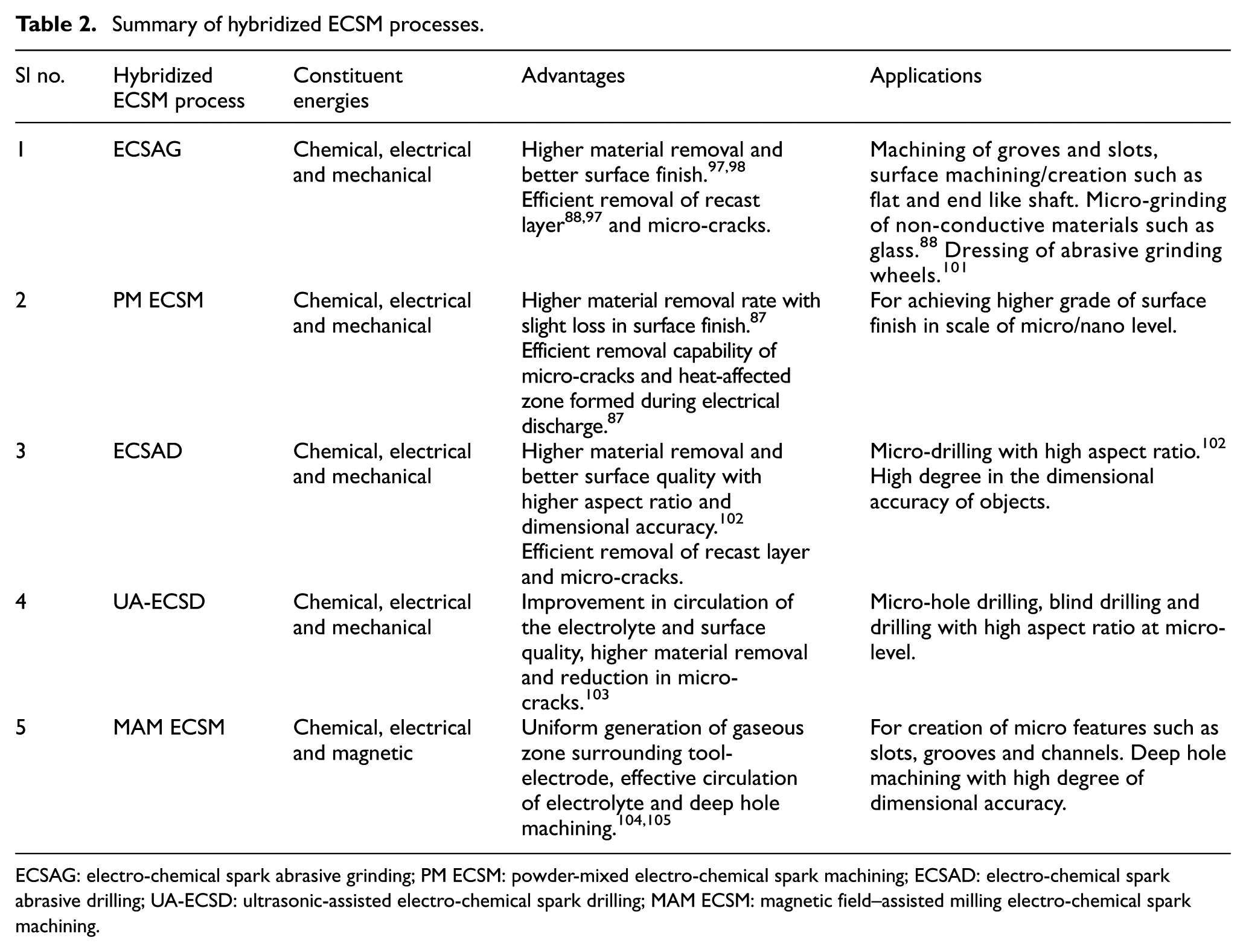
ECSAG: electro-chemical spark abrasive grinding; PM ECSM: powder-mixed electro-chemical spark machining; ECSAD: electro-chemical spark abrasive drilling; UA-ECSD: ultrasonic-assisted electro-chemical spark drilling; MAM ECSM: magnetic field–assisted milling electro-chemical spark machining.
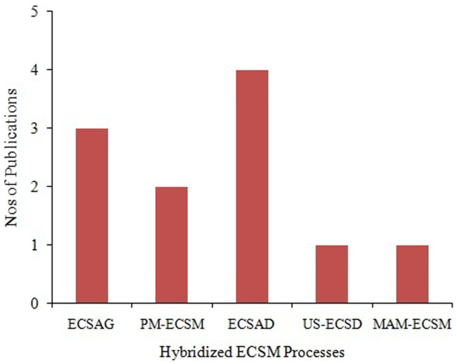
Numbers of publications on different hybridized ECSM processes.
Future scopes of research
After sophisticated studies, it has been analyzed that only limited hybridized ECSMs are developed till now. There are so many scopes to develop new hybridized ECSM processes to improve the capabilities of the existing processes. The ultrasonic vibration (20–30 kHz) with low amplitude is widely used to develop the hybrid machining processes in the field of EDM and ECM to increase the productivity.109–114 The basic purposes of hybridization of EDM/ECM with ultrasonic vibration are higher material removal, better surface finish and reduction in micro-cracks on machined surfaces and to minimize debris accumulation in the gap. Instead of this, it also assists in stable, uniform and strong spark formation during sinking or drilling EDM through which high aspect ratio can be achieved. 114 In the same way, ultrasonic vibration aided with different configurations of ECSM process for development of newer machining processes can perform better than the existing processes. Therefore, ultrasonic-aided ECSM processes such as UAS ECSM, ultrasonic-assisted milling ECSM, ultrasonic-assisted turning ECSM, ultrasonic-assisted TW ECSM and ultrasonic-assisted grinding ECSM can be developed. In addition to ultrasonic vibration in ECSM, the flows of electrolyte become more uniform, and much uniform flow of current in the machining zone leads to generation of stable and strong sparks resulting in reduction in micro-cracks, higher material removal with better surface finish and higher aspect ratio of holes.
The application of ultrasonic vibration can be implemented with abrasion-based hybridized ECSM process and the developed processes can be named as ultrasonic-assisted AG ECSM or UA ECSAG to improve the capability of grinding phenomenon in the micro ECSM process. The applications of abrasive particles in grinding ECSM as ECSAG are to increase material removal with better SQ, to remove recast layers and micro-cracks. Such ECSAG process becomes an appropriate method for dressing of metal-bonded abrasive wheels.108,115 Therefore, the UA ECSAG process can be become more valuable for dressing of conductive/non-conductive grinding wheels. 105 Instead of uniformed metal-bonded grinding wheel, the segmented type grinding wheel gives better performances in grinding EDM process. 116 Such alternative method of erosion and abrasion can be tested with abrasive-based ECSM process as slotted ECSAG process and such process is also hybridized with ultrasonic vibration to get better machinability.
Instead of machining by abrasion, saw-cutting ECSM can be developed as a new technique to cut the difficult-to-cut material. Such cutting process is already developed to cut conductive material in ECM process by Liu et al. 117 and in EDM process by Kumar and Singh. 118 Liu et al. 117 investigated that gas (H2) bubbles are formed at the edge of saw as shown in Figure 15. Therefore, these bubbles can be used for spark creation with application of discharge voltage as ECSM process. Such developed process can be known as saw-cut ECSM and it can be developed as ultrasonic-assisted saw-cut ECSM with application of ultrasonic vibration. In general, spark generation becomes difficult or no spark is generated during cutting of workpiece materials of thickness greater than 5 mm because of the difficulty in generation of H2 gaseous film. 119 Wang et al. 119 developed wire sawing ECSM for cutting of hard and brittle insulating materials using on-process oil film–coated diamond wire and found higher material removal with better surface finish. This can become an emerging field of research.
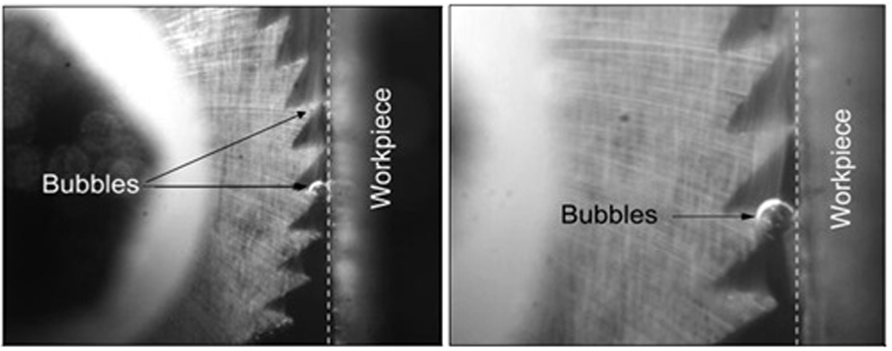
Hydrogen bubbles’ formation during saw-cut ECM process. 115
The electrically conductive-based abrasive particles such as Gr and SiC were only tested in ECSM process resulting in improvement of machining efficiency and it is also helpful for uniform generation of gas (H2 gas) surrounding tool-electrode.91,100 Such behaviors of mixing particles were tested in EDM process to improve the overall machinability.120–123 Therefore, such particles can be mixed with different electrolyte fluids used in ECSM process, and different hybridized ECSMs can be possible such as PM sinking ECSM, PM drilling ECSM, PM milling ECSM, PM W ECSM, PM turning ECSM, PM saw-cut ECSM and PM ECSAG to get higher machinability. Instead of mixing powder into electrode, two different electrolytes such as NaOH and KOH were mixed and such electrolytes were tested in ECSM process by Paul and Hiremath. 124 They investigated that mixed electrolyte gives higher material removal for ECSM of silicon wafers with tungsten carbide (dia = 300 µm) tool-electrode and creates a new area for research.
The roles of magnetic force in EDM and ECM are widely used by researchers to gain higher productivity.125–130 Even though limited application of magnetic force in ECSM process has been found as magnetic force–assisted Milling ECSM. The magnetic force in milling ECSM process shows their potential in machining as higher material removal, better surface finish and higher depth of cut. 106 Therefore, different magnetic force–aided hybridized ECSM can be possible such as magnetic force–assisted sinking ECSM, magnetic force–assisted drilling ECSM, magnetic force–assisted turning ECSM, magnetic force–aided grinding ECSM and magnetic force–aided ECSAG. The roles of ultrasonic vibration with magnetic force in EDM/ECM are tested by several researchers.131–135 Therefore, ultrasonic-assisted ECSM can be further combined with magnetic force to get simultaneous advantages of ultrasonic vibration and magnetic force in the field of ECSM as magnetic force and UAS ECSM, magnetic force and UAD ECSM, magnetic force and ultrasonic-assisted ECSAD, magnetic force and ultrasonic-assisted milling ECSM, magnetic force and ultrasonic-assisted turning ECSM, magnetic force and ultrasonic-assisted saw-cut ECSM, magnetic force and ultrasonic-assisted grinding ECSM, magnetic force and ultrasonic-assisted ECSAG and so on. The summery of possible hybridized ECSM processes are summarized in Table 3.
List of hybridized ECSM processes to be developed.
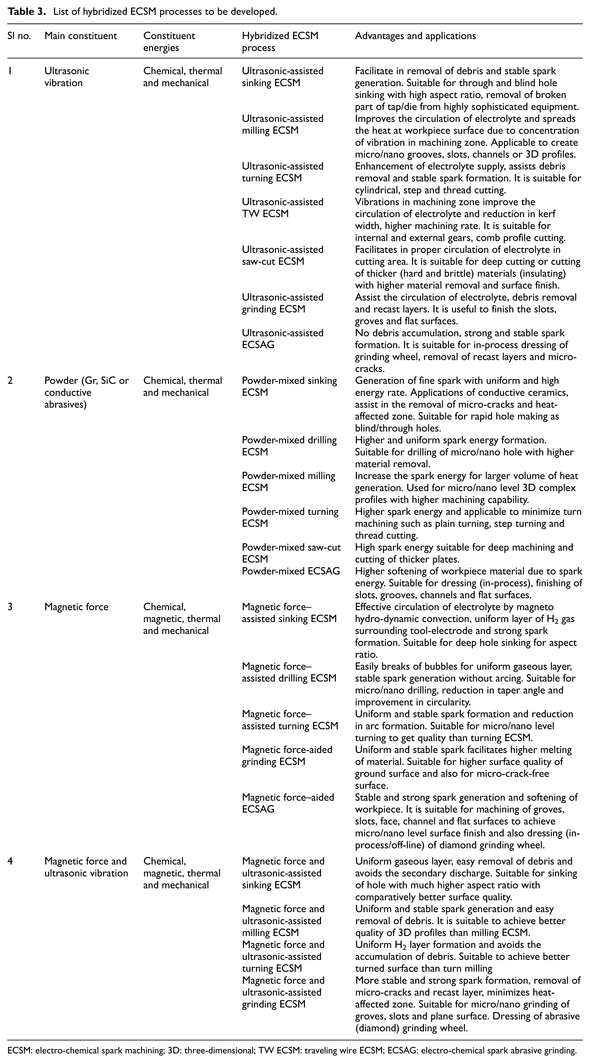
ECSM: electro-chemical spark machining; 3D: three-dimensional; TW ECSM: traveling wire ECSM; ECSAG: electro-chemical spark abrasive grinding.
Conclusion
In this article, a review on ECSM process with developed configurations and hybridization has been discussed and focuses on possible research works. The main purposes of different methods/techniques introduced in ECSM process are the same, to improve/enhance machining performances with no defect at low cost. After inclusive study of published research article related to ECSM in different views, the following conclusions are summarized as follows:
ECSM is a hybrid machining process that comprises the features of EDM and ECM processes for shaping of electrically conductive and non-conductive materials at micro-level machining.
ECSM process developed in different configurations such as drilling ECSM, TW ECSM, milling ECSM, sinking ECSM, grinding ECSM and turning ECSM positively create complex profiles with better SQ during machining.
Grinding ECSM becomes an appropriate method to develop micro-tools for micro-machining related to EDM, ECM or ECSM process.
Turning ECSM has been recently developed and it can be developed in different turning modes such as taper tuning, face turning and step turning.
Saw-cut ECSM is a new configuration of ECSM and is a good approach for slice/disk cutting of difficult-to-cut non-conductive materials.
Hybridization with ECSM process is a novel trend to enhance the productivity of ECSM process. The developed hybridized ECSM and the number of articles published on them are shown in Figure 14.
Ultrasonic vibration–assisted ECSM enhances the flow of electrolyte into the gap resulting in reduction in arcing phenomenon. Such an approach effectively improves material removal, SQ and reduces micro-cracks.
Mixing of powder in electrolyte as a PM ECSM rises the discharge voltage resulting in material removal capability. The mixing of abrasive particles in electrolyte such as SiC effectively removes micro-crack, and heat-affected zone is formed during electrical discharge as a result of improvement in SQ. On the other hand, Gr particles reduce the direct impact of spark energy on workpiece surface which improves SQ.
Abrasive-aided grinding ECSM shows their potential to remove micro-cracks and recast layer formed due to spark energy at the workpiece surface. It significantly enhances material removal and SQ. It is a unique technique for dressing of micro-tools/wheels.
The applications of magnetic field in ECSM assist in deep hole machining with better quality because effective circulation of electrolyte facilitates MHD convection. On other hand, magnetic force plays an important role in forming uniform layer of gaseous zone surrounding tool-electrode. This is because, it easily breaks of the bubbles resulting in stable spark creation which contributes to higher machinability.
Several more hybridization of ECSM process can be possible to get better performances of the existing ECSM process. Some possible hybridization in ECSM process is summarized in Table 3 which becomes advantageous for researchers to develop new process/method in the field of ECSM to machine the difficult-to-machine materials.