
Abstract
Adiabatic shear evolution in serrated chip will lead to inevitable impacts on the tool failure with the cutting speed increasing. The high-speed machining experiment of railway steel was carried out by applying the cemented carbide insert. The chip morphology transformation with white layer during adiabatic shear evolution was observed, and its influence on the tool failure mechanism on rake face was further investigated microscopically. The experimental results were concluded that the isolated segment chip formation due to adiabatic shear fracture weakened the wear effects on the rake face under higher cutting speed. The periodical cycle from adiabatic shear banding to fracture which resulted in a thermal–mechanical coupling effect mainly influenced the rake face failure mechanisms.
Introduction
The serrated chip development in high-speed machining is usually characterized by adiabatic shear evolution that includes adiabatic shear instability (ASI), adiabatic shear banding (ASB) and adiabatic shear fracture (ASF). The ASB evolution generally transforms serrated chip to isolated segment chip, resulting in some inevitable impacts on the high-speed machinability. The formation and fracture of serrated chip have been extensively investigated in machining the poor thermophysical materials1–3 and the rate hardening materials.4–6 However, the influence of adiabatic shear evolution in chip-flowing process on the tool failure has not been comprehensively understood.
As for the formation and fracture mechanism of serrated chip, Recht 1 and Komanduri et al. 2 early ascertained the catastrophic thermoplastic instability–induced adiabatic shear was the main reason of serrated chip formation. Subsequently, the theory of adiabatic shear–induced serrated chip formation was supported by more scholars.3,7 The periodic cyclic fracture theory was proposed by Shaw and Vyas 4 to illustrate the serrated chip fracture in machining hardened steel. Elbestawi et al. 5 and Poulachon and Moisan 6 found brittle crack on the machined surface of serrated chip in cutting high-hardness steels. Wang et al. 8 found that the crack could easily form in transformed band (TB) of serrated chip. Su and Liu 9 hold that the brittleness enhancement of work material played a leading role in serrated chip fracture. Guo and Yen 10 and Hua and Shivpuri 11 simulated the crack propagating process in serrated chip through applying finite element method (FEM) software. Gu et al.12,13 found that the fracture of serrated chip was of energy-related characteristic.
In addition, some scholars observed the tool failure behaviors during the serrated chip formation. Ginting and Nouari 14 observed that the plastic deformation and tool failures, such as chipping, cracking and flaking in machining Ti alloy. Calamaz et al. 15 analyzed the tool wear through a numerical two-dimensional (2D) cutting model. Others found that the chipping and brittle microcracks were formed on the tool edge and rake face at higher cutting speed with coated carbide tools16,17 and uncoated carbide tools.18,19 Su and Liu 20 found that the thermal softening effect of the workpiece property influenced the tool wear mechanisms in high-speed cutting AerMet100 steel with coated carbide tools. Cui et al. 21 investigated the characteristics of tool failure mechanisms and surface roughness in high-speed milling of hardened steel. Sun et al.22,23 found effect of tool wear on chip formation during dry machining Ti alloy. From the studies and investigations mentioned above, it is inferred that the tool failure is unavoidable in the cutting. Although the tool wear and the cracking on the tool edge are generally observed under different cutting conditions, the targeted studies on the intrinsic relation between adiabatic shear evolution and tool failure have not been legitimately conducted.
Therefore, the main purpose of this work is to investigate the influence of adiabatic shear evolution on the tool failure mechanisms in high-speed machining of railway steel. The high-speed machining experiment and the microscopic experiment are carried out. The serrated chip morphologies in different stages of adiabatic shear evolution and the tool failure states on rake face are detected microscopically. The intrinsic influences of adiabatic shear evolution on the tool failure mechanisms are revealed.
Material and method
In the cutting experiments, U75V steel was selected as the work material for its wide application in the heavy railway material. The metallographic structures of the work material and the uncoated cemented carbide insert are shown in Figure 1. The material hardness of the railway steel is about 39 HRC and the micro-structure is mainly the proeutectoid ferrite and pearlite (Figure 1(a)). The chemical compositions of the railway steel (wt%) are that C: 0.70–0.78, Si: 0.50–0.80, Mn: 0.70–1.05, P: 0.03, S: 0.03, V: 0.04–0.12. The micro-structure of the cemented carbide insert is composed of fine WC hard phase and Co binding phase (Figure 1(b)).
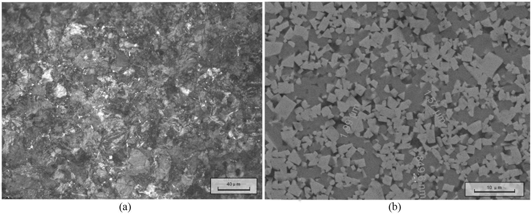
Metallographic structures of: (a) U75V railway steel and (b) cemented carbide insert.
The machining tests were carried out on a milling computer numerical controlled (CNC) under dry cutting condition. The arrangement of experimental setup is shown in Figure 2. The spindle speed and the feed determine the cutting speed and the cutting thickness, respectively. The spindle speed increased above 1000 m/min until the chip fractured into small isolated segments. The feed was 0.2 mm/r, and the tool rake angle was −10°. In order to investigate the influence of adiabatic shear evolution on the tool failure, the cutting was maintained about only a few seconds to reduce the friction effect. The work material was machined into a rectangle plate with a thickness of 2 mm and fixed horizontally with the work table to satisfy the orthogonal cutting condition. The cemented carbide inserts was fixed with the face milling cutter. The chips obtained in the tests were embedded vertically into curing denture acrylic. The chip cross sections were examined through metallographic microscope after polishing and etching. The tool failure morphologies on rake face were examined through scanning electron microscope (SEM).
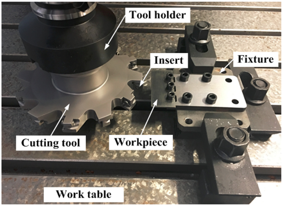
The arrangement of experimental setup.
Results and discussions
Adiabatic shear evolution
The chip-flowing behavior reflects the thermal–mechanical coupling effect in the cutting process. Adiabatic shear evolution in the chip morphologies in high-speed machining U75V steel at feed of 0.2 mm/r were shown in Figure 3. When the cutting speed increased from 100 to 300 m/min, the thick deformed bands (DBs) generated in serrated chip (Figure 3(a) and (b)). When the cutting speed increased to 500 m/min, the thin and white colored TBs generate in serrated chip (Figure 3(c)). When the cutting speed increased from 800 to 1100 m/min, the cracks generated in the TBs and almost propagated to the bottom of the chip (Figure 3(d) and (e)). When the cutting speed increased to 1300 m/min, the serrated segments completely fractured along the TBs, forming isolated segment chips (Figure 3(f)).
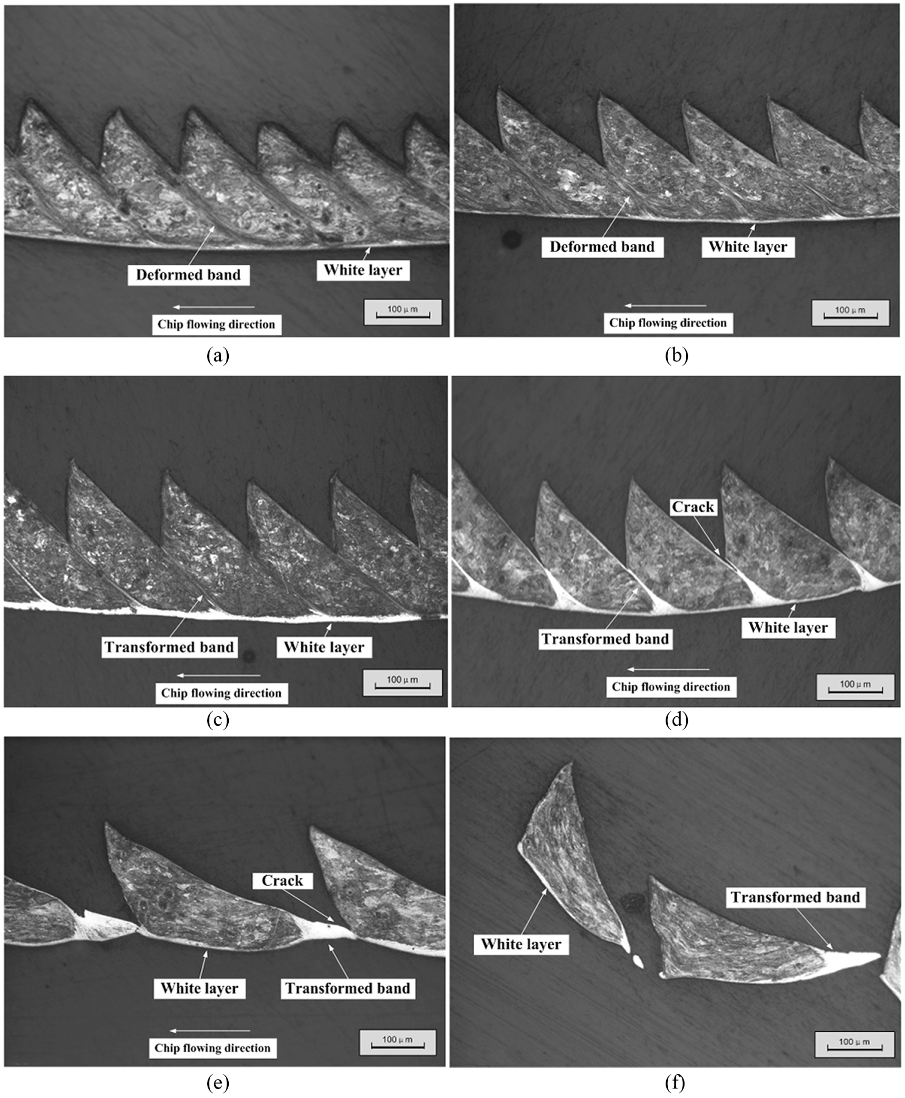
Adiabatic shear evolution in high-speed machining U75V railway steel at feed of 0.2 mm/r: (a) v = 100 m/min, (b) v = 300 m/min, (c) v = 500 m/min, (d) v = 600 m/min, (e) v = 1100 m/min, and (f) v = 1300 m/min.
The critical cutting speeds of adiabatic shear evolution in high-speed machining of hardened steel and stainless steel have been studied in the previous works.12,13 It is indicated that the temperature rise in a thin TB was remarkable, reinforcing the toughness of ASB. With the evolution of adiabatic shearing in serrated chip, the energy convergence in ASB is continuously increased until the fracture occurs between the segments. The converged energy is released in the form of fracture. Moreover, the negative rake angle increases the pressure stress and suppresses the heat diffusion in ASB. For more details refer to the study of Gu et al.12,13
White layer formation
It is interesting to notice that the white layer was formed on the bottom of the chip. The white layer formation reflects the tribological behavior between the tool–chip interfaces. It can be observed in Figure 3 that the color of white layer gradually becomes bright with the cutting speed increasing. The rubbing state was more obvious between the tool–chip interfaces at the cutting speed of 500 m/min, resulting in an increase in white layer thickness (Figures 3(c) and 4(c)). With the cutting speed increasing further, the friction effect on chip bottom decreased, leading to an increase in white layer thickness due to fast cooling in the cutting (Figure 2(d)–(f)).
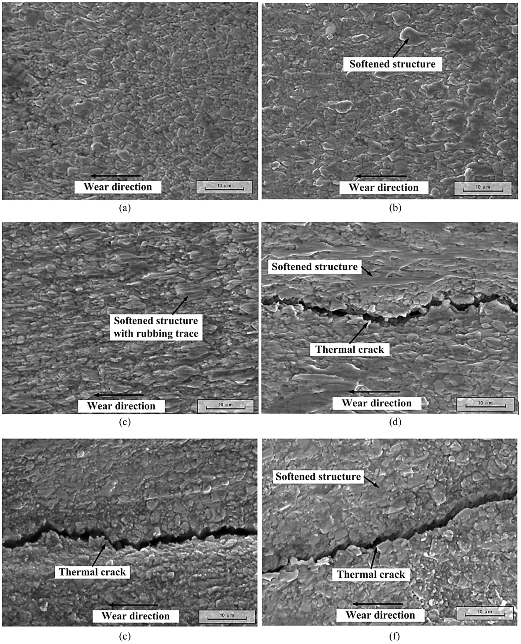
SEM views of rake face failure in high-speed machining U75V railway steel: (a) v = 100 m/min, (b) v = 300 m/min, (c) v = 500 m/min, (d) v = 600 m/min, (e) v = 1100 m/min, and (f) v = 1300 m/min.
In the machining experiments, due to the fast heating and friction between the tool–chip interfaces, the phrase transformation was possibly occurred in the white layer below the austenitizing temperature. Although the formation of white layer is related closely to the friction state between the tool–chip interfaces, adiabatic shear evolution in primary deformation zone (PDZ) can significantly contribute to fast heating on the chip bottom in a short tool–chip contacting time. Therefore, to a great extent, adiabatic shear evolution in high-speed machining process mainly determines the thermal–mechanical coupling effect that is imposed on the tool rake face.
Tool failure mechanism
The tool failure on rake face was detected through SEM examinations as shown in Figure 4. It can be deduced from Figure 3(a)–(c) that the main wear pattern would be crater wear under relative low cutting speed. The regions of normal rubbing and softening structure can be observed on the worn rake faces. The main wear mechanism of rake faces during the formation of DBs and TBs in serrated chip was the combination of abrasion and adhesion. The hard phase and binding phase on the rake face were softened due to fast heating. A relatively low wear would be found in the formation of DBs as shown in Figure 4(a). With the transformation from DBs to TBs in serrated chip, the region of softening structure was enlarged on the rake face (Figure 4(b) and (c)). When the cutting speed increased to 500 m/min (Figure 4(c)), the formation of the thin TBs mainly contributed to fast heating and normal pressure on the rake face, resulting in the rubbing and softening traces on the worn rake face. The white layer thickness on the chip bottom reflected the heat and friction states.
It can be seen from Figure 4(d)–(f) that the thermal cracks appeared on the rake faces. Under the speed of 600 m/min, the white TBs with crack initiated in the serrated chip. Due to the accumulation of rubbing and thermal effects on the tool–chip interface, the softening structure covered on the rake face was further enlarged. Meanwhile, the thermal crack perpendicular to the cutting edge was appeared on the rake face (Figure 4(d)). Cui et al. 24 suggested that the thermal cracks on the rake face under high cutting speed was probably due to the higher tool temperature. In our experiment, the cutting time was controlled shortly, but the thermal softening and shocking effect due to the periodic cycle from ASB to fracture still cannot be avoided. The thermal softening on the rake face reached a maximum at the speed of 600 m/min. However, with the cutting speed increasing up to 1100 m/min, the thermal softening effect on the rake face was greatly weakened in the very short tool–chip contacting time (Figure 4(e)). Although the thermal effect between the tool–chip interfaces was decreased in isolated segment formation at the speed of 1300 m/min, the thermal crack was still observed on the rake face (Figure 4(f)). Gu et al.12,13 found that ASF induced the formation of isolated segment chip was an energy-related process. Therefore, it was inferred that the adiabatic shear evolution leaded to energy convergence to release, which significantly influenced the thermal–mechanical effect and the tool failure state.
Conclusion
In the high-speed machining of railway steel, the thermal–mechanical coupling effect imposed on the tool rake face depends on the adiabatic shear evolution from serrated chip to isolated segment chip. The region of softening structure on the tool rake face is enlarged with the transformation from DBs to TBs in serrated chip, and then gradually fades away on the occurrence of ASF. The main wear mechanism of rake faces is the combination of abrasion and adhesion. The occurrence of ASF weakens the rubbing and adhesive effects on the tool–chip interface. Although the white layer formation reflects the tribological behavior between the tool–chip interfaces, the adiabatic shear evolution which leads to the energy convergence and release in high-speed machining significantly influences the thermal–mechanical effect and the tool failure state.
Footnotes
Declaration of conflicting interests
The author(s) declared no potential conflicts of interest with respect to the research, authorship, and/or publication of this article.
Funding
The author(s) disclosed receipt of the following financial support for the research, authorship, and/or publication of this article: This work is supported by National Natural Science Foundation of China (No. 51601155).