
Abstract
In order to pursue excellent performance, especially in aerospace and weapon equipment industry, components with complex structure made of difficult-to-cut material (stainless steel, titanium alloy, high-temperature alloy etc.) are more and more applied. From the rough to the finished product, the material removal rate (ranging from 10% to 90%) may be large, the machining efficiency and material utilization are low, and the machining cost would be high using traditional milling or grinding method. One kind of thin hollow cathode having high strength is developed for electrochemical machining of complex structure. This cathode is expected to improve the machining efficiency and reduce the cost. The flow field design is a key problem to be solved. Fluid dynamics numerical analysis is used to optimize the cathode structure, and the design rules of cathode are given. Experiments are carried out to prove the correctness of the numerical analysis, cutting stability, accuracy, and surface quality are improved. Finally, different structures are successfully machined on the material of TB6 by thin hollow cathodes.
Keywords
Instruction
With the rapid development of modern industry, especially in aerospace and weapon equipment industry, components with complex structure made of difficult-to-machine material (stainless steel, titanium alloy, high-temperature alloy, etc.) are more and more applied. From rough to finished products, the material removal rate (ranging from 10% to 90%) may be large, the machining efficiency and material utilization are low, and the machining cost is high using traditional milling and grinding method. Compared to other machining methods, electrochemical machining (ECM) has no tool wear and no material hardness limits, the machining efficiency is high and the surface quality is good.1–6 Klocke et al.7–9 analyzed the machining efficiency of titanium alloy and high-temperature alloy using milling, electrical discharge machining (EDM) and ECM. He concluded that ECM has the highest comprehensive efficiency. Because of inherent advantages for machining difficult-to-cut material, ECM has received unprecedented attention.
Reasonable flow channel is necessary for ECM, many experts and scholars have made deep research on it. Aircraft1 manufacturing laboratory of Israel Haifa engineering institute created spherical cathode and machine prototype, and the cathode surface was full of holes for electrolyte squirting out. Complex surface could be machined by multiple-axis movement of spherical cathode.10,11 Xu et al. developed three-electrode feeding method to machine turbine blades and removed the mutation of the electrolyte flow channel. The profile accuracy was improved to 0.05 mm and the surface roughness was improved to Ra 0.36 μm.12,13 Wang et al. 14 designed the cathode with optimized flow channel to machine the whole impeller step by step; generating method was used in rough machining and forming electrode was used in finishing machining. Xu et al. 15 proposed a new method of synchronous machining, multiple tubular cathodes were driven by synchronous mechanism and started machining simultaneously, the shape and position of the electrolyte outlet holes on the electrode were analyzed and optimized, and finally, multiple channels of impeller were machined at the same time. Wang et al. 16 and Fang et al. 17 proposed method of electrochemical drilling with vacuum extraction of electrolyte and made the simulation and optimization of flow field in the distribution chamber. Zhu et al. 18 improved the machining stability of micro holes using pulsating flow field technology. Zhao et al. 19 studied the flow field design and process stability in ECM of diamond holed, and they verified that a short arc flow channel combined with vibrating feeding is capable of improving machining localization and process stability markedly. Guo et al. 20 utilized a scanning micro electrochemical flow cell (SMEFC) as a method of ECM, which could confine the electrolyte beneath a hollow cathode with the help of a suction head. Hou et al. introduced a new method to fabricate a large-area polydimethylsiloxane mask containing micro through-holes. Their experiments verified that it is feasible to obtain large-area micro-dimple arrays with high machining accuracy using the technique of ECM. 21
ECM using the thin hollow cathode could directly separate the workpiece and the remaining material, so the material utilization could be high reusing the remaining material. However, existent research on electrochemical cutting is mainly focused on microstructure. Zhu Di, Wang Kun, Wang Shaohua et al. proposed a series of measures to enhance the mass transport in micro-wire ECM, such as wire electrode micro-amplitude of vibration on axial direction, axial direction flushing, and circular wire electrode one-way silking, which achieved good results in microstructure machining. Zeng et al. 22 and Zhu et al. 23 improved the flow field using axial direction flushing with high-speed electrolyte, and the machining speed was greatly increased. Xu et al. 24 studied vibration-assisted wire electrochemical micromachining of array micro-tools, and they indicated that large amplitudes and high speeds of cathode vibration and large amplitudes and high frequencies of anode vibration could reduce the edge radius and improve the homogeneity of the slit width. Kim et al. 25 and El-Taweel and Gouda 26 studied on the effect of micro-wire cathode, high-frequency pulse voltage, feed rate, and electrolyte on the ECM. Because the diameter of the wire is small, the rigidity is poor and the cut slot is narrow. When workpiece is thick, the machining area is hardly flushed effectively, so the machining efficiency is low. Therefore, above research has significant effect on thin plate (thickness is less than 1 mm) and has low efficiency or almost could not be used on thick plate. Further research and improvement of fast electrochemical cutting technology for large thickness components are still needed.
This article develops a thin hollow electrode with high strength and establishes physical model of electrolyte flow field in machining area on three-dimensional parameter software Siemens NX. The electrolyte velocity distribution is computed on the platform of multi-physical field simulation software COMSOL, and the structure of cathode is optimized based on the simulation. Then, experiments are carried out to verify the correctness of the flow field analysis. Finally, different structures are successfully machined by the thin hollow cathodes.
Physical model of electrolyte
The principle of thin hollow cathode
In order to narrow the gap, a thin cathode is required; the wall thickness is 0.6 mm, the hollow thickness is 0.8 mm, and the cathode thickness is 2 mm (0.6 + 0.8 + 0.6). So, the cathode may be of bad stiffness and strength, and it is difficult to guarantee machining stability. As shown in Figure 1(a), with high pressure electrolyte in the cathode without strengthening rib, it would be expansive and distorted. And there would be vibration due to its lower stiffness during the machining. In order to avoid this bad phenomenon, the cathode is improved to consist of Part A and Part B which are assembled by the holding-on of wedge strength ribs (the rib angle is α), and both the sides are connected by laser welding as shown in Figure 1(b). Part A and Part B could be fabricated by wire cut electrical discharge machining (WEDM). The wedge strengthening rib has two functions: one is increasing the stiffness of the cathode itself and reducing the vibration; the other one is avoiding the expansion and distortion of cathode when electrolyte pressure is high. Figure 1(c) is the real picture of thin hollow cathodes with strengthening rib.
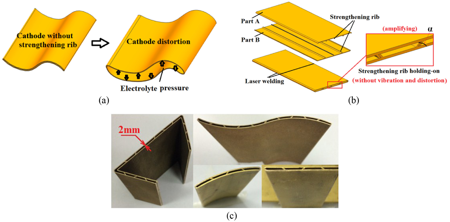
The thin hollow cathode: (a) distortion of cathode without strengthening rib, (b) the schematic of cathode with strengthening rib, and (c) real cathode with strengthening rib.
Physical model of electrolyte
However, cathode with strengthening rib shown in Figure 2(a) would make the electrolyte flow split, which lead to the nonuniform flow in machining area. Removing the end strengthening rib for a suitable length h (as shown in Figure 2(b)) is a compromising method to solve this problem. It could not only guarantee the cathode strength but also improve the uniformity of electrolyte flow. Four physical models with different structures are shown in Figure 2(c). They are Plan A, round corner cathode with complete rib; Plan B, round corner cathode with end rib removed for h; Plan C, right angle cathode with end rib removed for h; and Plan D, round corner cathode without rib.
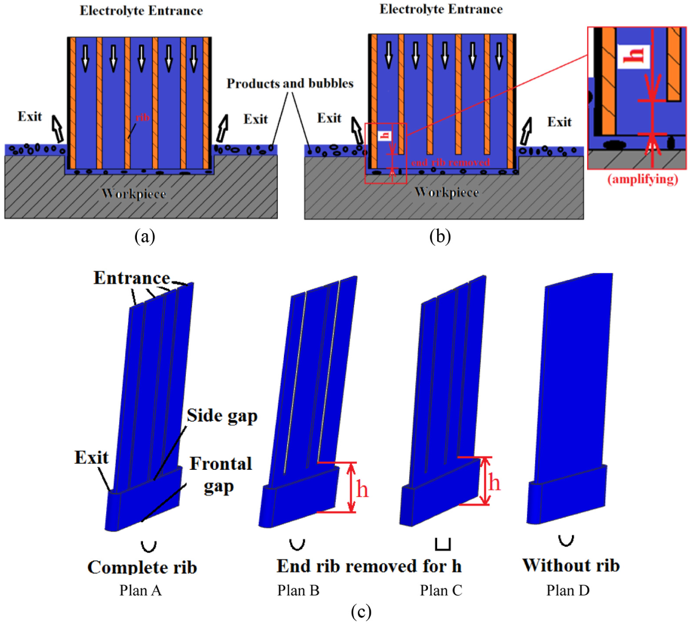
Forward flow of ECM and physical model of flow field: (a) cathode with complete rib, (b) cathode with head rib removed, and (c) physical model of flow field.
The mathematical model of electrolyte
Generally, the machining area should be flushed by electrolyte at a high speed, which could take out the Environmental and Combustion Control (ECM) products and the Joule heat, maintain the electrolyte temperature and conductivity with a constant value, replenish fresh electrolyte, and eliminate the concentration polarization.
Machining condition is as follows: the electrolyte is 20%NaCl + 10%NaNO3 solution, the density is 1180 kg/m3, the dynamic viscosity is
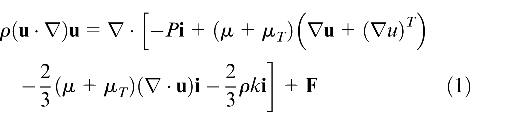
Based on the eddy viscosity hypothesis of Boussinesq, Navier–Stokes equation of viscous incompressible fluid is changed into
The incompressible fluid satisfies the continuity equation

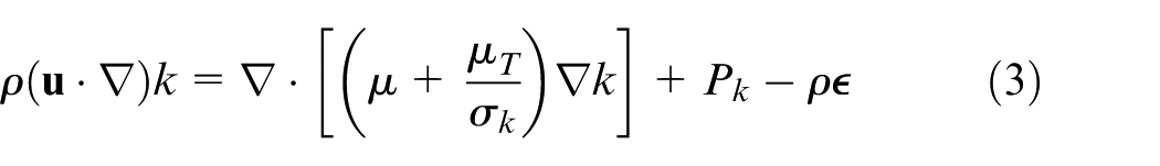
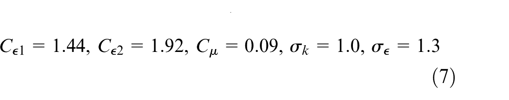
In order to make the model equations closed, introduce the standard k-ε two-equation model
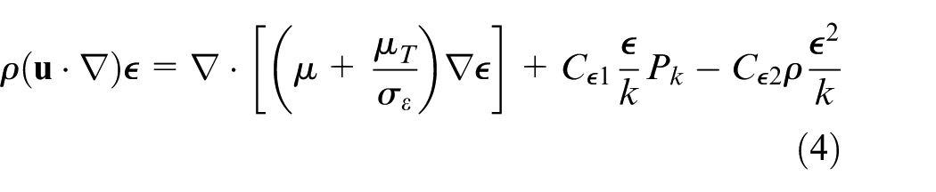
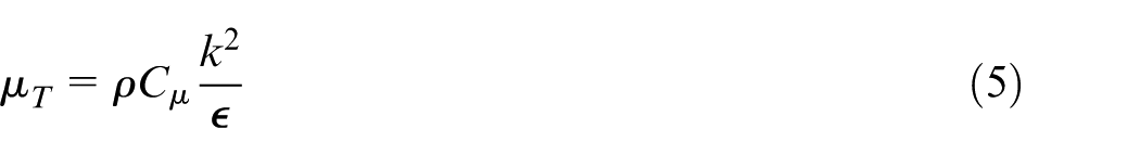
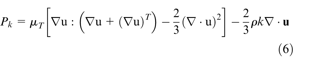
where
Simulation and analysis of flow field based on COMSOL
Simulation and analysis of different plans
The gap between the end of cathode and the workpiece is called the machining gap, and the uniformity of flow field plays an important role. Figure 3 shows the velocity distribution in machining gap. As shown in Figure 3, the region marked by red box is below the strengthening rib, and the velocity here is low. The reason could be explained by the conservation of momentum: the electrolyte from different through-holes collides in this region, which leads to a loss of speed. The more obvious the collision of flow line is, the more obvious the nonuniformity of the flow field is, so the collision of flow line is supposed to be avoided. When the cathode has complete strengthening rib (h = 0 mm), the streamline collision is most significant, as shown in Figure 4(a). When the end strength rib is removed for length of h = 10 mm, the extent of flow line collision is reduced, as shown in Figure 4(b). When the cathode does not contain strength rib, the flow line collision does not happen as shown in Figure 4(c), and the flow field uniformity is best. So, the collision of flow line becomes less obvious with the increase in h, and the uniformity of flow field becomes better with the increase in h.

Velocity distribution of frontal gap: (a) velocity cloud and (b) velocity along line A/B/C/D.
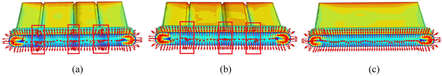
The collision of streamline in frontal gap: (a) Plan A, (b) Plan B, and (c) Plan D.
As shown in Figure 3(b), along the red line in Figure 3(a), the velocity line of Plan A has the maximum fluctuation, so the flow field uniformity is worst. The flow field uniformity of Plan D is best, but its stiffness and strength is the worst. The flow field uniformity of Plan B and Plan C is between Plan A and Plan D. The electrolyte velocity in right angle of Plan C is lowest (less than 5 m/s), which may cause the phenomenon of sparks or short circuit when the cathode feed rate V is high. It could be concluded that Plan B is the best. Cathode with end rib removed for h could not only improve the strength of cathode but also improve the uniformity of flow field.
The effect on the flow field uniformity of α and h
As shown in Figure 1(b), α is the angle between the strengthening rib and cathode; as shown in Figure 2(b), h is the length of removed strengthening rib.
As shown in Figure 5(a), the effect on flow field uniformity of h is significant. When h = 0, the velocity line has maximum fluctuation; when cathode does not contain rib, the velocity line has the minimum fluctuation. The flow field uniformity would be improved with the increase in h. From the analysis of Figure 5(b), when α = 15°, the fluctuation of velocity is the smallest, and the fluctuation of velocity line increases slightly with the increase in α. On the whole, the effect of α on the flow field uniformity is not obvious. From the point of view of flow field uniformity, cathode without strengthening rib has the best structure. But in order to meet the strength requirement, the cathode must have strengthening rib. The flow field uniformity could be improved by changing the values of α and h.
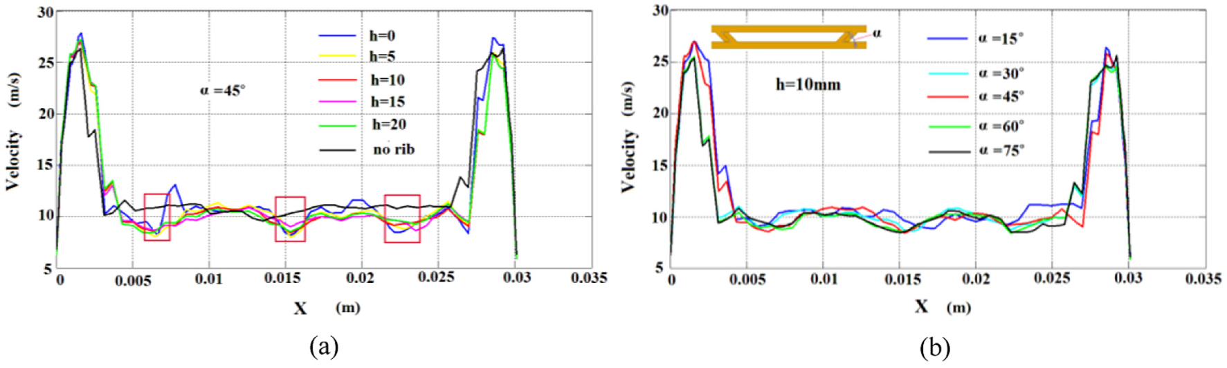
The effect of h and α on velocity: (a) the effect of h on velocity and (b) the effect of α on velocity.
As shown in Figure 6, α = 45° and h = 10 mm; the strengthening ribs are divided into different number of sections. As the number of sections increases, the degree of streamline collision increases slightly. Although the increasing trend of streamline collision is not significant, it is harmful to the uniformity of flow field. So, the later used strengthening rib is the same as Plan B.
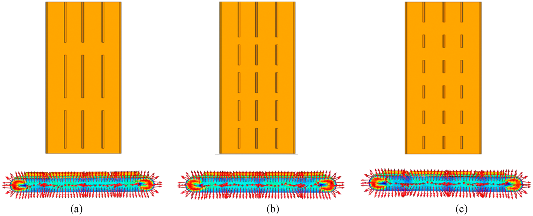
The collision of streamline in frontal gap with different strengthening rib: (a) three sections of rib, (b) five sections of rib, and (c) six sections of rib.
The design rule of α, h, and s
The distance between the adjacent two strengthening ribs is S. In the design of thin hollow cathode, it is necessary not only to consider the strength requirement but also to consider the flow field uniformity. Through above analysis, it could be known that the strength of cathode and the uniformity of flow field could be changed by changing the values of α and h. According to the analysis and experience, when pressure of internal electrolyte is below 1.8 MPa, the selection of α, h, and s could be 15° ≤ α ≤ 75°, 5 mm ≤ h ≤ 15 mm, and 5 mm ≤ S ≤ 15 mm
From the point of view of improving uniformity of flow field, α should take a smaller value and h and S should take a bigger value. From the point of view of improving the strength of cathode, α, h, and S should take a smaller value.
Experiment study
The fabrication of insulating layer
Due to strong corrosion of electrolyte, epoxy resin, silicone high-temperature insulating coating and other organic coatings are easy to fall off or damaged when the electrolyte temperature is high. In this article, the technology of baking enamel insulating layer is explored. The specific process is as follows: (1) pre-treatment— sand blast the cathode to surface roughness of Ra 3–6 μm, remove the surface oil by acid, and then clean it by purified water. (2) Spraying—according to different cathode material (copper, stainless steel, etc.), select corresponding enamel glaze to spray on the cathode and then dry the enamel. (3) Baking the enamel—place the cathode into the furnace with temperature of 840 °C ± 5 °C for 3–5 min and then take out the cathode; it could be used when cooled to room temperature. The enamel insulating layer is strong and durable even when the temperature is 100 °C.
Experimental study of linear cathode
Experiment with different h
Experiments are carried out to verify the analysis of flow field. The machining parameters are peak values of pulse voltage of 24 V, 3 kHz frequency, 90% duty cycle, 10%NaNO3 + 20%NaCl solution used as an electrolyte, electrolyte temperature of 40 °C ± 0.5 °C, and titanium alloy TB6 test piece material. Cathodes with α = 45°, h = 0/10/15 mm, and s = 8.5 mm are used in the following experiments. The feed rate of cathode is V = 2–2.5 mm/min.
As shown in Figure 7(a), the feed rate of cathode is 2 mm/min; when h = 0 mm, there are bumps just below the strength ribs. The possible reason is that electrolyte velocity here is low, so the flushing force is weak, which results in low dissolution rate. This situation may cause sparking or short circuit here when V is larger, so the feed rate of cathode could not be high and the machining stability may be bad. In the experiments, with h = 0 (Plan A), the short circuit happens when V ≥ 2.2 mm/min and with h = 10 mm (Plan B), the short circuit happens when V ≥ 2.4 mm/min.
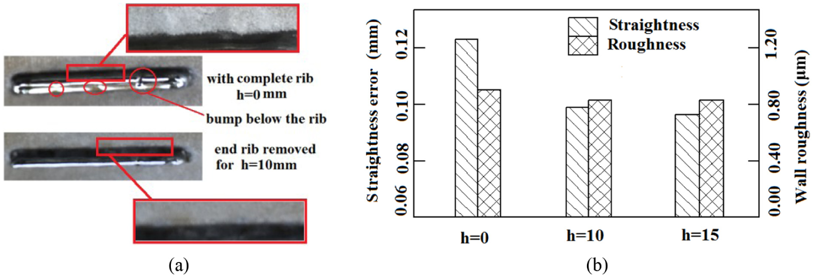
Cutting quality of linear cathode (V = 2 mm/min): (a) machined slots and (b) slot quality.
In order to save time, depth of machined slot is 10 mm. Data are collected from five different positions of the slot entrance (shown in Figure 8). The slot width W and straightness error Se are calculated by equations (8) and (9) respectively

where W is the width of machined slot and di is the width of five different positions of slot (shown in Figure 8); di is measured by coordinate measuring machine of CENTURY 977. Se is the straightness error of machined slot.
Width measurement of machined slot.
The slot cut by cathode with complete strengthening rib (Plan A) presents obvious curve. Measured by three coordinate measuring machine CENTURY 977, the straightness error of slot is 0.125 mm. The wall roughness measured by roughness measurement Taylor Hobson is 1.15 μm. When h = 10 mm and 15 mm (Plan B), the straightness error is less than 0.095 mm, and the surface roughness is less than 0.85 μm. So, the cathode with end rib removed for a certain length h has a higher machining accuracy and surface quality. The result of Figure 7 proves the correctness of the flow field analysis.
Experiment with different U
The machining parameters are peak values of pulse voltage of 19–24 V, frequency of 3 kHz, 90% duty cycle, 10%NaNO3 + 20%NaCl electrolyte solution, electrolyte temperature of 40 °C ± 0.5 °C, and 0.6 mm/min cathode feed rate (V). Material of test piece is titanium alloy TB6. Cathode with α = 45°, h = 10 mm, and S = 8.5 mm is used. The morphology of the machined slots is shown in Figure 9.
Slot morphology with different peak values of pulse voltage U (V = 0.6 mm/min).
As shown in Figure 9, when V = 0.6 mm/min, all slot’s width are larger than 2.86 mm, and all straightness errors are larger than 0.311 mm. The reason of the condition may be that the cathode feed rate is low, the machining time of every section would be long, and therefore, the side gap would be large. Large side gap makes the flow field nonuniform, which makes the dissolution of material nonuniform, so the straightness error is large. High feed rate of cathode should be used.
Experiment with different V
In order to select reasonable cathode feed rate, cathodes with α = 45°, h = 10 mm, and s = 8.5 mm are used. As shown in Figures 10 and 11, when the cathode feed rate is low, the cutting slot is wide and the straightness error is large. With the increase in feed rate, the slot becomes narrower and the straightness error becomes lower. The reason of this condition may be that when using larger feed rate, the machining time of every section would be shorter and the slot would be narrower. With small side gap, the flow field is more uniform, so the dissolution rate is more uniform and cutting accuracy is higher. When the feed rate of the electrode reaches 2.2 mm/min, the cutting width is 2.48 mm and the straightness error is 0.871 mm.
Slot morphology with different feed rate V.
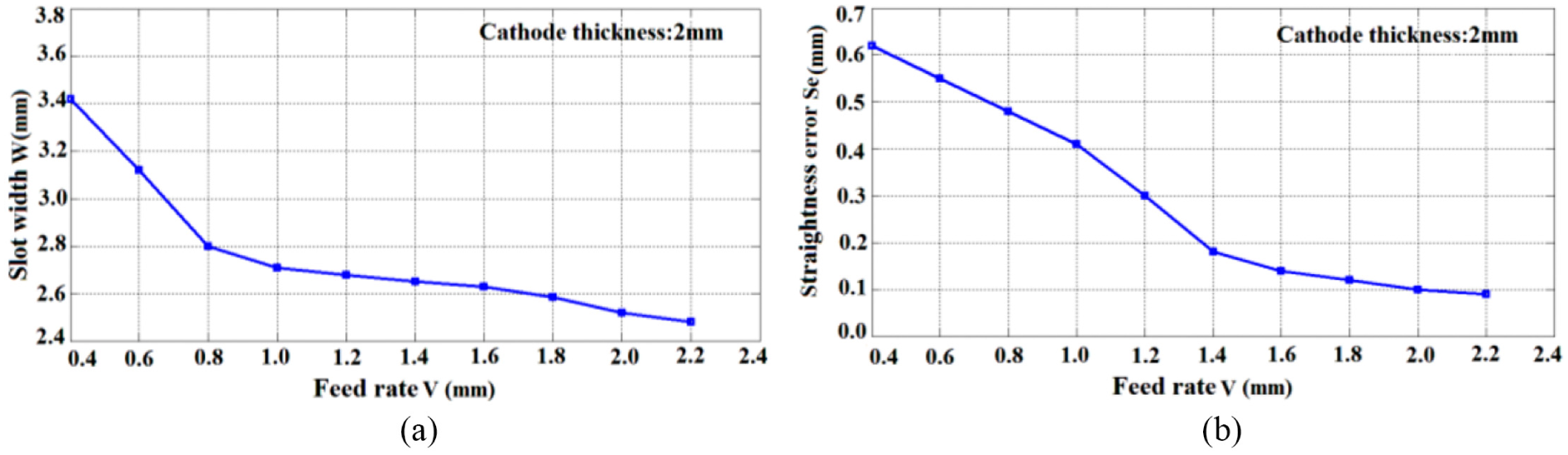
Machining quality with different feed rate V: (a) slots width with different feed rate V and (b) straightness error with different feed rate V.
ECM of complex structures
Figure 12 shows different structures machined by thin hollow cathodes with α = 45°, h = 10 mm, and s = 8.5 mm. The machining parameters are peak value of pulse voltage of 24 V, frequency of 3 kHz, 90% duty cycle, 10% NaNO3 + 20% NaCl electrolyte solution, electrolyte temperature of 40 °C ± 0.5 °C, and cathode feed rate of 1.8–2.2 mm/min. The width of cutting slots is less than 2.68 mm, the cutting profile error is less than 0.115 mm, and wall roughness is less than 0.885 μm.
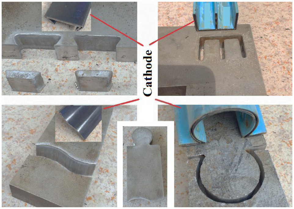
Real picture of structures machined by thin hollow cathode.
As the cathode moves only downward, the time of ECM is only related to the thickness of workpiece, but not to the shape and size of the workpiece. The thickness of workpiece shown in Figure 12 is 20 mm, so the ECM time of every workpiece is 20/1.8 ≈ 12 min. By measurement, the time of ECM is 30%–80% of computer numerical control (CNC) milling. (The time of CNC milling is varied based on the shape and size of workpiece, and the time is measured by the machining simulation of software Vericut.) Compared to CNC milling, the efficiency of ECM will be higher when the shape of workpiece is more complex and the size is larger.
From above analysis and experiments, the thin hollow cathode could be used for machining complex structures made of difficult-to-cut materials. This technology could be the fast rough machining of components with high accuracy requirement or fast final machining of components with low accuracy requirement. In the case of large-capacity power supply and machine tool are available, large-scale thin hollow cathode could be used to cut large complex structure; the machining efficiency could be greatly increased and the machining cost could be greatly reduced. At the same time, the remaining material could be reused, so the utilization of precious metal could be improved.
Conclusion
The thin hollow cathode with strengthening rib has good stiffness and strength. The vibration, expansion, and distortion of cathode would be avoided. So, the machining stability could be improved.
From the point of improving uniformity of flow field, α should take a smaller value and h and s should take a larger value; from the point of improving the strength of cathode, α, h, and s should take a smaller value. The selection of α, h, and s could be 15° ≤ α ≤ 75°, 5 mm ≤ h ≤ 15 mm, and 5 mm ≤ s ≤ 15 mm.
Due to the strong corrosion action of electrolyte, epoxy resin, silicone high-temperature insulating coating, and other organic coatings are easy to fall off or damaged when the electrolyte temperature is high. The enamel insulating layer has good corrosion resistance, insulation effect, and strong binding force with the cathode. It is strong and durable even when the temperature is 100 °C.
In the case of large-capacity power supply and machine tool are available, large-scale thin hollow cathode could be used to cut large complex structure; the machining efficiency could be greatly increased and the cost could be greatly reduced. At the same time, the remaining material could be reused, so the utilization rate of precious metal could be improved.
Footnotes
Declaration of conflicting interests
The author(s) declared no potential conflicts of interest with respect to the research, authorship, and/or publication of this article.
Funding
The author(s) disclosed receipt of the following financial support for the research, authorship, and/or publication of this article: This work is sponsored by National Science and Technology Major Project of China (2015ZX04001201) and Industry-University-Research Special project of AVIC (cxy2013BH04).