
Abstract
Additive manufacturing takes a growing place in industry tanks to its ability to create free-form parts with internal complex shape. Yet, the quality of the final surfaces of the additive manufacturing parts is still a challenge since it doesn’t reach the required level for final use. To address this issue, it is necessary to measure the form and dimension deviation in order to plan post-process operations to be considerate. Moreover in a context of industry 4.0, this measurement step should be fully integrated into the manufacturing line as close as possible to the additive manufacturing process and post-process. We introduce in this article an inline measurement solution based on a robot combined with a laser sensor. Robot allows reaching most of the orientation and positions necessary to digitize complex parts in a short time. The use of robot for digitizing is already addressed but not for metrological applications. Robots are perfectly designed for velocity, ability and robustness but their poor positioning accuracy is not compatible with measuring requirements. The strategy adopted in this article is to provide an algorithm to generate path planning for digitizing additive manufacturing parts at a given quality of the resulting cloud of points. After a discussion about the geometric and elastic model of the robot to identify the one that answers the quality requirements, the performances of the robot are evaluated. Thus, several performances maps are introduced to characterize the behavior of the robot in its working volume. The qualification of the digitizing sensor is also performed to identify relation between digitizing parameters and the quality of final cloud of points. Using data resulting from the qualifications of sensor and robot and the parts CAD model, the algorithm allows generating path planning to ensure the final quality necessary to measure the shape deviation.
Keywords
Introduction
Additive manufacturing (AM) is a rising field in industry because of its convenience to create complex parts. Many recent reports from governmental agencies, European Commission 1 or national research institutions2,3 have shown the increasing place of AM technology and its economic impact in near future. It is now generally accepted that AM represents such a change that requires to rethink of the entire design, manufacturing and control chain. 4 Despite many advantages, today it is still not reasonable to consider a part obtained by AM as a finished ready-to-use part—this is particularly true for metal additive manufactured parts. 5 Additional manufacturing operations as post-processing with complementary process as machining are usually necessary to have a functional component. AM can be defined as the process that allows building a three-dimensional (3D) part by joining material layer by layer thanks to a digital definition based on the CAD model 6 and as opposed to subtractive manufacturing technologies. It is therefore by nature that this technology generates shape deviation on parts. Shape deviation and texture are the most noticeable undesirable external effects on additive manufactured parts. Those effects are generated by many different sources, but the height of each layer and the relaxation of thermal stresses7,8 play a major role. In this context it is necessary to have a metrological feedback of the parts for the quality control and the post-process planning. The measurement step can be considerate as the control step between two manufacturing processes (Figure 1).
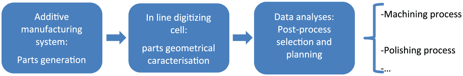
Aims and place of a measurement cell in an AM production line.
It allows characterizing the shape deviation of additive manufactured parts, information that will be used to select and define the characteristics of the next manufacturing process necessary. Indeed, it is often necessary to plan a post-processing step with subtractive manufacturing techniques to polish, to reduce the surface stresses or just to reach the required tolerances that are not reachable with AM. 9 In order to scale up the production and to keep the cadence of production, an inline measurement process would be the best option. Classical CMM technology provides probably the best metrological feedback, but due to its time consumption, it is not possible to use it for an inline measurement especially when it is added to an AM chain where the measurement of each part is necessary for planning of the post-processing. We propose here the use of a robot combined with a Laser Triangulation Sensor (LTS) to directly measure each part on the production line with few assembly/disassembly compared to an equivalent CMM measurement.
Robots have poor pose performances that limit their use for high precision task especially for measurement applications, but they offer a great flexibility of movement with 6 degrees of freedom (DoFs) and a high speed of execution. Those characteristics stay very attractive and could allow the 3D digitizing of complex parts made by AM with the continuous reorientation provided by robots. Hence, the robot facilitates the integration of the measurement process on production lines. Yet using a robot for such application is impossible until its pose accuracy is improved, as defined in ISO 9283 and confirmed by industrial needs.10,11
In this context, this article introduces the development of a 3D digitizing cell using a robot as displacement and an LTS for parts measurement. The specifications on the part to be produced by AM induce digitizing quality requirements to carry out a geometrical measurement and to address the post-process planning. A strategy is addressed to use the robot for digitizing parts with the required quality of digitized points. This strategy also pays attention to the digitizing time to minimize it. This results in a digitized part with a given quality and an optimized speed. The final digitizing time and quality highly depend on the robot and on the LTS performances, so we study both in this article. The calibration of laser sensors is well known; 12 however, there is no standard to measure LTS performances and we must adapt methods. 13 Robot performances are deduced from experiments and models, but models used for industrial robots are usually simple geometric models using the DH convention14,15 plus one stiff parameter for the angular elasticity. This is not enough for an accurate description of robot behavior, so we investigated a detailed and original geometric and elastic model. We also experiment an original method for a quick and convenient identification of model parameters. Robot performances are heterogeneous in robot workspace, 16 so we have to choose a work zone to realize the digitizing where robot performances correspond to quality and speed needs. This can be done with a constrained path, 17 so a path planning algorithm is introduced, based on robot performance cartography and on LTS performances. The aim is to reach the quality targeted for AM by using the robot and the LTS in their best configurations. The introduced strategy allows thus to create a path that guarantees the quality requirement on the points digitized and that optimizes the digitizing time or other criteria like the energy consumption (not investigated here).
An external measurement system is used to control the path followed by the robot so as to respect the quality of the resulting digitizing. It allows correcting the path and, used with the robot model, it brings a redundancy that provides a more robust result. By this way, the quality of robot positioning is not an issue anymore since the positioning is provided by the external system and thus its quality is depended on the accuracy of the latter one.
After introducing the components of the digitizing system, the global strategy for path planning is presented. The third section presents the geometric and elastic model of the robot and in the fourth one we detail the performance indexes helpful for the path planning to exploit robot capabilities. The last section deals with the LTS calibration and integration as well as the use of the external measurement system before ending with a conclusion and some perspectives about future work.
Path planning strategy for a robotized digitizing
The robot 6 DoFs allow a complete reorientation of the LTS and thus a more flexible path is generated to digitize the complex parts made by AM. But we also need to respect digitizing requirements and to optimize other criteria like the digitizing time, the energy consumption or maybe the final digitizing quality. For those reasons, we detail here the path planning algorithm and the integration of robot performances and LTS capabilities in this algorithm. It results in the calculation of the best path depending on robot and sensor performances.
Optical measurement and robotized digitizing cell for AM
With AM, many new challenges have emerged from a metrological point of view, for instance:
The assessment of geometrical capacity of AM systems using metrological artefact.18,19
In process measurement for monitoring the laying of materials during the manufacturing and off course the shape deviation measurement for quality control and post processing planning. 9
In this article, we will focus on the last point for quality control. There are many different technologies for optical form measurement, but laser triangulation and structured light projection are the most appropriate and offer the best compromises between volume measurement, time consumption and accuracy required by industries such as aerospace.13,20 In this article, the part digitizing will be performed thanks to a laser sensor. This solution is more flexible than structured light projection for the measurement of complex and free-form surfaces, which characterized the parts generated by AM. Indeed, the laser plane can be easily oriented and thus facilitates the accessibility of the whole part. This is especially true if a robot is used as a displacement system. Many applications integrate robots to use some of their advantages, for example, a lot has been done in machining with robots.21–23 Brosed 24 uses a robot for digitizing, but exploits it to carry, position and orient parts. The robot behavior (model and performances) is not taken into account in the path planning process, and many robot capabilities are unused.
The path planning is essential to improve the robot posing as it allows taking advantage of its 6 DoFs.25–28 Moreover, that path planning should pay attention to the real robot capabilities in terms of speed or posing quality, so it should be based on robot performance indexes. 16 But as related to Zha, 28 most of path generators do not take into account performance indexes. The robot’s model used for the path planning also plays a significant role in the resulting quality of the digitized points. And performance indexes are mostly calculated with the robot model. This is the reason why the selection and the definition of an adapted robot model are a major concern29,30 developed in this article.
In this context, we introduce a digitizing cell (Figure 2), which uses a robot and two contactless sensors: one for the part digitizing and one for an external control of the robot path.
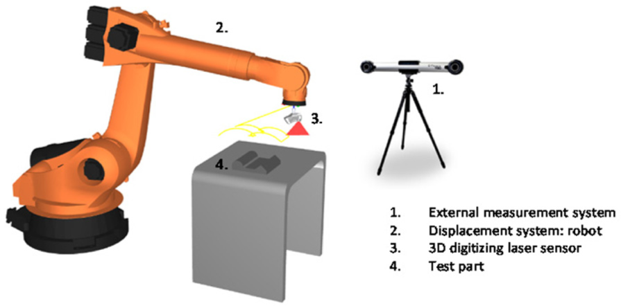
Multi-sensor digitizing cell.
This cell involves the use of a global strategy resulting in digitized points with respect to the AM needs while taking advantage of the robot’s capabilities. This strategy is developed in two parts: the path planning related to robot and LTS performances, and the deviation control of the robot end-effector. Considering the small field of view of the CTrack, we allow it to lose the track of the end-effector. The path is corrected later when the effector comes back in the CTrack vision field. In this case, the path is regularly corrected during the process. In order to increase the correction frequency (for instance, the sample time), we intend to equip the cell with more advanced tracking devices.
Strategy for path planning algorithm
The path planning algorithm gives the best trajectory regarding the quality requirements on the resulting cloud of points. The obtained path is actually a set of path points, each point is characterized by a position and an orientation of the robot end-effector. When the robot computer numerical control (CNC) reads the planned path, it uses the robot model to convert points from the Cartesian space (position and orientation) to the joint coordinate space (six angles for robot articulations). During the execution of the trajectory, more path points will be created from the existing points, by linear interpolation (to smooth the trajectory).
Figure 3 describes the path planning process. It starts with the translation of the AM needs in terms of requirements on the digitizing quality. A CAD part is also needed for the process as it provides the part geometry. Then, the sensor performance knowledge allows us to transform the digitizing requirements into a local path specification, giving the digitizing distance and the angle between the sensor and the part. Then we look for areas in the robot workspace where the path could take place with the local path specifications. So multiple areas are found where sets of path points are partly defined: the local specifications partly fixed the position and orientation of the path points. Among the admissible areas, and with the remaining freedom on path point positions and orientations, we look for the best path in terms of speed or robot posing quality. Finally, we pick the best path among the optimized path from each area.
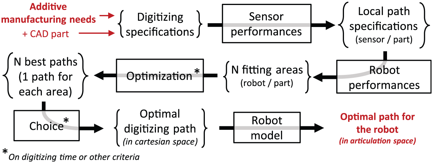
Path generation strategy for digitizing.
To apply this strategy, a perfect knowledge of the LTS characteristics is essential. The laser sensor used for digitizing is a KREON KZ25. We evaluated its performances thanks to an assessment protocol: QualiPSO. 13 The next section introduces a model of the robot used to calculate robot performances but also used to generate the final robot path in Figure 3.
Geometric and elastic robot model
The path planning strategy is used to optimize the speed of the digitizing process and to meet a high level of tolerancing requirements imposed by functional use of the AM parts. But this strategy relies on the accuracy of the robot model used in the algorithm. Actually the robot model defines the relation between the Cartesian space and the joint space. The path is planned in the Cartesian space but the robot motion is defined in the robot joint space which explains the need for a model. So a robot model not detailed enough would take away the resulting path from the planned path and would lower the quality of the digitizing points. Furthermore, many robot performances depend on the robot model as presented later in the fourth section. The digitized point’s quality and the robot performance indexes calculation put this model as the main basis of our strategy. The model used by Kuka into the robot’s CNC to generate path is poorly detailed in terms of robot defaults like deformations and backlashes. In order to represent as close as possible the real robot behavior, we propose a model that takes into account geometric defaults coming from manufacturing limits and assembly as well as non-geometric ones.
Model selection and definition
In the literature, the Denavit–Hartenberg (DH) model is the best-known geometric parameterization convention. 14 It is mostly used with a different convention: the DH modified model, as it is more convenient. 31 It is often completed with the Hayati 32 parameter, which handles consecutive parallel axes. As geometric models are well known, we focus more on elastic models representing non-geometric defaults. Many elastic models are based on the DH parameterization, completed with some non-geometric defaults.33–35 To define an accurate and complete model, three techniques are generated:
The FEA model (finite elements analysis) uses finite elements to compute robot elastic deformations.36,37
The MSA model (matrix structural analysis) uses the Euler–Bernoulli beam theory to compute the deformations of the robot links. 38
The VJM model (virtual joint model) uses virtual springs with 6 DoFs where all displacements and backlashes are concentrated. 23
We need a flexible model, able to take into account all significant robot defaults on the digitizing quality, so we choose an adaptable model that can contain any default: the VJM model. It is initially only made for deformations in articulations. Thus, we modified the 6 DoFs virtual springs into a translation vector and a rotation vector, for both deformations and backlashes and applied to both links and articulations. The resulting model is adaptable and can be completed with more detailed models of joints and links.39,40
The VJM model is based on the DH geometric parameterization convention and adds its virtual joints between the geometric components of the model (links and articulations) as explained in Figure 4. Our modified VJM model can handle all non-geometric phenomena into the translation and rotation vectors of its virtual joints. So now we need to model deformations and backlashes of robot joints and links to put them into virtual joints.
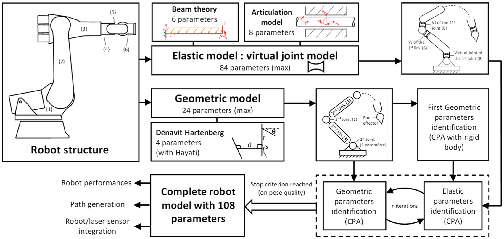
Calibration strategy for an elastic and geometric model of the robot, based on the modified VJM adapted model.
The robot links are modeled using the beam theory from the MSA model. 38 For each link there are five stiff parameters and one parameter for the mass, which allow to express the link deformation under an external load.
A similar theory does not exist for joint modeling as joints are commonly less detailed. So we use the standard ISO 230-1 in a polar frame to get four error terms: 41
Each of them includes a deformation and a backlash to get a total of eight parameters for each joint.
Yet, we need to pay attention to special issues. Actually we cannot model all links with the beam theory. For those that do not respect beam conditions, we use an FEA model. Otherwise, since the third link and the fourth link are necessarily aligned, their length cannot be identified separately.
Model calibration: identification of parameters
The external measurement system (Figure 2) is used to identify all model parameters, that is to say geometric and elastic parameters. Identifying parameters with a contactless method is more convenient as digitizing can be done on production lines. Parameters must represent the robot behavior in its entire workspace and not only in few spots used for the identification by most calibration methods. 12 For this reason, we develop here the circle point analysis (CPA) method 42 that uses the entire workspace.
In this method, the positions of robot joints are identified separately. The joint moves in the field of view of the external measurement system that follows a target placed on the end-effector. Then the circle’s arc measured allows finding the joint position. The CPA identifies all joint locations and we calculate the robot parameters between joints. This method gives good joints positions as we follow a joint in its complete availability range, so we get accurate parameters. Contrary to classic methods, we don’t try to minimize position errors in few points, but we directly estimate robot parameters.
The CPA identification is initially made for geometric calibration, so we adapted this method for elastic parameter identification. To do so, the identification experiments were done while modifying the efforts on the robot end-effector.
The calibration of the robot parameters with the CPA method follows the strategy presented in Figure 4. A first estimation of geometric parameters is done by assuming the robot components as rigid. Then we use it as an input for the first iteration to get elastic and geometric parameters. The calculation goes on until a given accuracy is reached by all parameters. The estimation of elastic parameters is done with the Levenberg–Marquardt algorithm. Once parameters are identified, the robot model is exploited for path planning and for performance index calculation.
Definitions and uses of robot performance indexes
As mentioned in the second section, the result of the path planning algorithm will be a trajectory made of path points. Those path points give successive positions and orientations for the robot effector in the robot Cartesian workspace. Robot performances are needed to find possible path with the robot according to digitizing requirements and to LTS capabilities. This results in multiple possible paths with respect to the quality needed for the digitizing of AM parts. And for each path, the path points are not totally fixed: successive positions and orientations can change a bit while still respecting requirements. So robot performances also help to select among all possibilities the best path and the best path points (positions and orientations) in terms of digitizing speed or quality. For this optimization, we use performance indexes mostly based on the robot model. So it is interesting to see how the quality of index calculation depends on the quality of the robot model introduced in the previous section.
The assessment of robot performances permits to generate cartographies that help us to meet digitizing quality and to optimize the digitizing time, so performances need to describe robot speed and positioning quality. In order to handle the random part of robot posing, we need a performance index on the robot fidelity to follow a path. So among existing indexes, 16 we look for quality and speed-related indexes as well as other criteria indirectly linked to speed or quality. And during the path planning process, all indexes will be taken into account with different weights according to their importance for the calculation.
A flexible path by minimizing articulation availability
The articulation availability was first used by Liegeois 43 to keep joints away from their limits, that is to say to keep an amount of available movement. Trying to maintain this index high results in a smooth and flexible path. Yet this index does not handle the singular configurations, so it must be used carefully and with other indexes like manipulability or the condition number.
This index requires the knowledge of joint limits to compare them with the current joint position as in equation (1). Then the index is a mean of each joint position divided by their limits as shown in equation (2)
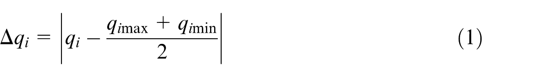
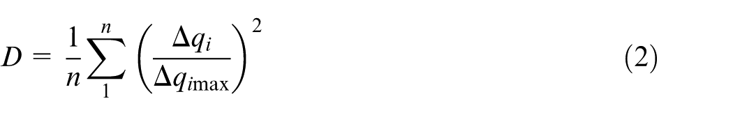
As this index helps to stay away from joint limits, its cartography represents the robot reachability like in Figure 5 where the index can vary from 0 (best availability) to 1. This allows to quickly eliminating unreachable workspace areas and simplifying the path planning.
Articulation availability for a vertical orientation.
Manipulability index for robot speed and quality
The manipulability index was created by Yoshikawa
44
to represent robot speed or posing quality. It calculates the robot speed capability for a given configuration and depending on each joint speed capability. This calculation of the manipulability index

There is another use than speed capability control for this index. A high manipulability means that little move of joints generates a big movement of the effector and so a very bad resolution. Conversely, a bad manipulability means a good resolution on the end-effector movement. Thus, the manipulability inverse represents the robot accuracy, and the manipulability index can be simultaneously used to determine robot speed capability and robot posing quality.
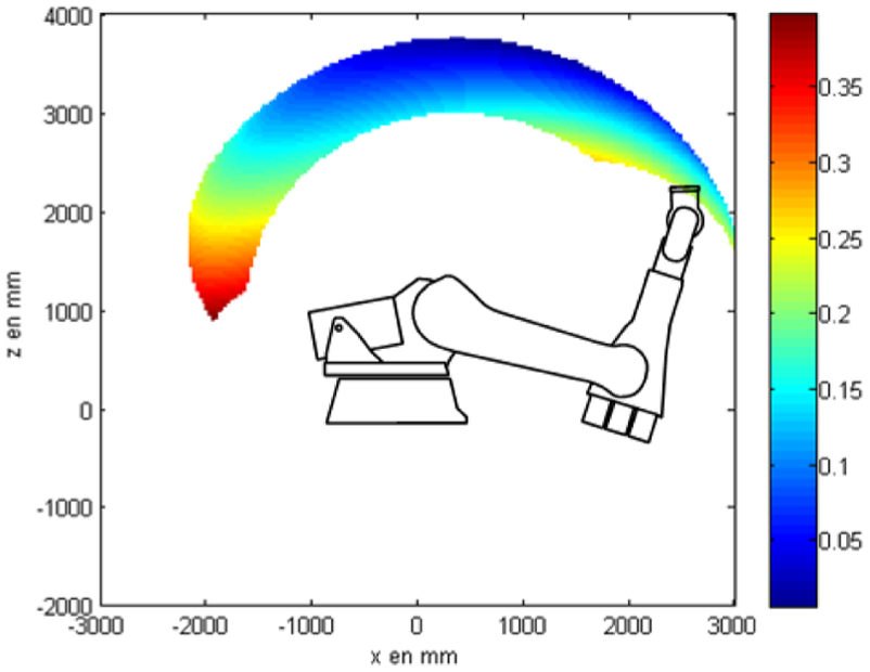
Since equation (3) uses the Jacobian matrix, the manipulability calculation requires the use of the robot model. In order to ensure the quality of the manipulability index, we need a model close to the real robot behavior, which means a good modeling and a good calibration. We see again the importance of the robot model inside the path planning process. For a vertical orientation of the end-effector, Figure 6(a) illustrates a cartography of the manipulability index calculated with the identified robot model in an area limited by the articulation availability
(a) Robot manipulability cartography for a fixed orientation of the end-effector. This cartography shows areas where the robot can generate high speeds. (b) Condition number cartography through the robot working area.
Condition number to control the path generation quality
Khan and Angeles 45 introduced the condition number to define the matrix conditioning and thus limit error propagation in calculation. The condition number calculated in equation (4) is based on the Jacobian matrix of the robot model, which makes another index dependent on the model
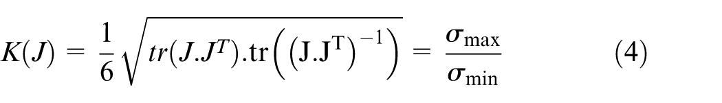
This index is used for many purposes: accuracy, dexterity or error propagation. For instance, it helps seeing the velocities disparities between joints. A low index means a good repartition of velocity capability among joints and a high index shows that an axis is near its speed limit. Figure 6(b) shows a cartography of this index for a vertical orientation of the end-effector in an area limited by the articulation availability. We can see that areas to avoid for good matrix conditioning are clearly situated.
End-effector repeatability with the robot repeatability model
In robotic vocabulary, the repeatability is the capacity of a robot to leave and return exactly on a point, that is to say the uncertainty of robot posing. This capacity is measured on few points in the robot workspace and the mean value corresponds to the robot repeatability. This is a global value for the entire workspace so it does not represent the true robot behavior, especially since the repeatability capacity highly depends on the current robot configuration. Thus, we developed a repeatability model giving the robot repeatability in a given configuration, which is more accurate than an average value for all configurations. The basis of this model was done by Brethe who built the robot repeatability from the six joint repeatability values, 46 which are the capability of joints to return in an angle. We went further by also making joint repeatability models, depending on the forces on joints and the joint acceleration and speed. Finally, we get an accurate model to calculate robot repeatability for a given configuration; however, the identification of this model requires the identification of all parameters linking the joint repeatability to the joint forces, to the accelerations and to the speeds. We conducted a series of experiments to determine the more influential parameters on each joint behavior, depending on forces, speeds or accelerations.
The cartography of repeatability shows the most reliable areas where the robot will closely follow the path planned.
Qualification and integration of sensors used in the digitizing cell
In order to increase the quality required for the AM application, we use an external measurement system to control the execution by the robot of the planned path. Moreover, we use this system to calibrate the robot model, so the quality of the identified model parameters depends on this external system. This section focuses on the qualification of this system and of the used LTS.
External measure of the digitizing
The digitizing cell components are as follows: a 6 DoF robot as a displacement system (support), an LTS to digitize parts and a stereovision system, the CTrack, as the external measurement system. This last component is a major part of the cell as it helps for many purposes in the path planning.
First, the external measurement system is used to follow the robot path during execution and to control deviation, even though it lengthens the cycle-time with additional calculations. 47 The robot model and its calibration are well fitted, but a correction of the path ensures the quality of the digitized points. The deviation control of the executed path is identified with the external measurement system, and then it computes the correction and finally it generates a new path and sends it to the robot CNC. The total computation time must be short enough compared to the robot cycle-time in order to really correct the path.
The robot joint coordinates (angles given by sensors) and the robot model allow computing the current configuration of the robot, which is given to the LTS to acquire digitized points. The CTrack can be used to replace the robot joint coordinate if sensor information is not accessible, or it can be used as a redundant way to reinforce sensor data.
Finally, this external measurement system is used during the robot model calibration with the CPA method (described in the third section). So a good qualification of the CTrack is essential to be sure to obtain good robot parameters, and for all other uses of this system. Thus, we check the adequacy of the external measurement system capabilities with requirements on the CPA method and on path controlling. For this purpose, a specific assessment protocol has been carried out.
Integration of the laser sensor
The LTS has its own model and its own parameters that need to be identified for the configuration used thanks to a calibration process. The calibration is an important step since it affects the quality of the final digitizing points. The sensor calibration can be divided into two parts: the internal and external calibration. The intrinsic parameters describe the geometry of the laser sensor components, they place the two-dimensional (2D) CCD matrix (the camera) with regard to the laser plane and detail the camera characteristics (focal, resolution, etc.). This allows calculating the 3D coordinates of the point digitized in the sensor frame. The intrinsic parameters describe the sensor itself, they are commonly given by the constructor and the internal calibration process is not accessible to the user.
The LTS has extrinsic parameters that are used to place the sensor relatively to the displacement system (the robot). In order to integrate the LTS to the digitizing cell, we need to find those parameters. Once we know the configuration of the LTS in relation to the robot, and with the knowledge of robot current configuration, it is possible to convert the 3D digitized point from the sensor frame to the global cell frame. To get extrinsic parameters, a calibration gage is used. 12
The LTS integration can be done in two different ways: the sensor can be fixed to the robot support, 12 or the LTS can be static in the robot workspace and the robot can hold the part to digitize. 24 In most cases, the sensor is carried by the robot but for inline measurement into an AM chain this solution is not optimum for two reasons: the measurement cannot be performed with the part placed into the AM system due to accessibility issues and the necessity to remove the part from the AM system to the post-processing system. For these reasons, we have introduced a digitizing cell where the part is removed from the AM system by the robot which run the digitizing path in front of the LTS before placing the part in the next post-process system.
Finally, we need to qualify the digitizing capacity of our digitizing cell. A metal benchmark part was designed with a specific geometry to test the cell capacity to digitize plans, angles and curves. Then both LTS integration cases (static or mobile) are set up and the assessment starts to identify the behaviors for the following:
The digitizing quality through the computation of the noise and the completeness on the generated cloud of points;
The digitizing speed with or without our path optimization;
The flexibility of the cell to digitize complex parts.
This specific qualification is made for this cell as its size prevents from using a classic method. 48 It helps us to know whether the cell can digitize a given part made by AM, regarding AM specifications. Yet before those qualification experiments, a validation protocol must be carried out to ensure the validity of the path planning strategy and of the components calibration. We use a calibrated artifact and the external measurement system to compare the posing quality of the robot with our model and with the model used by Kuka in the robot’s CNC. We begin with the same starting point and we calculate end points with both models at a theoretical distance equal to the artifact length. This is done for various configurations. Similar experiments are done to compare a classic path and a path optimized by our algorithm, by looking at the exact position of path points.
Conclusion
AM technology has open up new design possibility especially for free-form and complex parts. But till today, the low surface quality and the form deviation that characterized parts generated by AM (especially for metal AM) is a limitation to produce ready to use parts. In this context, the control quality by measurement and for post-process planning is required. This article is a first step to introduce a solution to integrate this measurement step into the manufacturing line which will avoid the part’s disassembly and its transportation to and from the outline classical measurement cell. It is reasonable to considerate that this solution will save time and will facilitate the post-treatment of AM parts. Moreover, thanks to the robot accessibility, the presented solution allows digitizing complex parts with none or few parts repositioning which also contribute to saves time. The path is generated automatically from the part CAD model and has an optimized speed. The capability to digitize with a robot for parts control in an AM context is a request that would allow saving time and resources. Actually the measurement step needs to be flexible and convenient to be on the production line and to be able to digitize the produced complex parts. The most appropriate displacement solution is a six-axis robot that responds to those needs. Yet digitizing with robots is still few developed nowadays, and robots advantages are rarely exploited. Contrary to the previous work, the strategy developed in this article tends to take advantage of full robot performances and digitizing sensor capabilities to obtain optimized digitized points for a control application. To do so, an optimized path is identified among an admissible set of paths previously calculated with robot and sensor capabilities. The path planning process focuses on the final required quality for digitized points and the digitizing time. In order to reach the level of quality compatible with the AM specifications, geometric and elastic models have been defined to detail robot behavior. The digitizing cell is completed by an external measurement system used for path deviation control and for digitized point calculation in order to avoid the poor positioning of the robot. This strategy can also be applied to other applications needing a convenient way to control parts on a production line. For instance, large parts like aeronautic parts currently require complex measurement devices 49 with significant logistics, where our strategy could be applied.
Footnotes
Declaration of conflicting interests
The author(s) declared no potential conflicts of interest with respect to the research, authorship and/or publication of this article.
Funding
The author(s) received no financial support for the research, authorship and/or publication of this article.