
Abstract
Robotic actuators such as geared MR actuators must improve their torque capacities and reduce their size to increase system integration density. MR clutches are at the heart of geared MR actuators and conventional machining is a major hurdle to downsizing because it requires having close tolerance for machining and assembling a large number of small parts. This paper studies the potential of nested 3D printed MR clutches to improve the torque density of geared MR actuators at small scales. Nested 3D printed MR clutches are multi-disk MR clutches where the rotor and stator are fabricated simultaneously on a single 3D print. A prototype is designed, built, tested and compared to similar conventionally made MR clutches. The prototype weighs 84 g and can transmit a maximum torque of 0.88 N.m. The fabrication process is fast and simple, and the performance levels well surpass those of comparable machined MR clutches. The manufactured prototype doubles the torque density and multiply respectively by 4 and by 10 the torque-to-inertia and torque-to-viscosity ratios compared to equivalent machined MR clutches. Results show that nested 3D printing of MR clutches is an effective manufacturing process and opens the door to a new generation of high-performance mechanical transducer.
Keywords
1. Introduction
1.1. Motivation
Collaborative robots are designed to work close to humans so they must show safe and fast behavior. Their actuators must have a high torque density while having low mass and inertia. To ensure the back drivability of such robot—which is the ability to move it by its end effector—the actuator system must show low friction and inertia (Lebel et al., 2021). Magnetorheological (MR) actuators have been shown suitable for those applications, by decoupling the inertia and friction from the motor and transmission and thus reducing the reflected mass, friction and inertia of the end effector (Shafer and Kermani, 2011a; Veronneau et al., 2018). They are used in devices that are described having “potential for safe, robust and highly versatile robotic interaction” (Fauteux et al., 2010), and Shafer and Kermani (2011a) describe MR fluid promising and well suited regarding human-robot collaboration.
Such MR actuators have been used in direct-drive configuration (Pisetskiy and Kermani, 2021), or with gearing ratios (Veronneau et al., 2018, 2020; Véronneau et al., 2022). The presence of a gearing ratio between the motor and the MR clutch allows the use of smaller motors and clutches, reducing the overall mass and volume of the actuator. To maximize torque density of the actuator, the clutch should be placed as close as possible to the motor with the highest gearing possible (Figure 1). Because clutch inertia and viscosity effects are multiplied by the square of the output gearing ratio R2, the MR clutch must have very low inertia and viscosity to ensure safe behavior and back drivability while having the highest gearing.
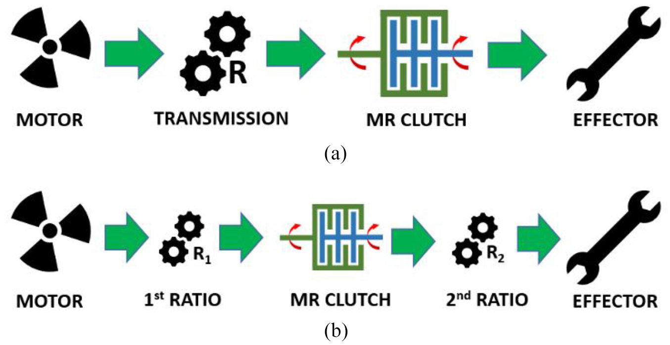
Location of the MR clutch in the power line: (a) after the gearing ratio and (b) closer to the motor.
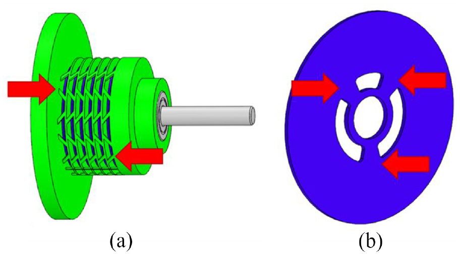
A robotic joint using gearing before and after the MR clutch has already been designed and tested in a parallel work (Figure 2) (Véronneau et al., 2022). The robotic joint is composed of two independent power chains, each composed of a motor, a MR clutch and a two-stage gearing ratio. They work either together to reach high torque, or in antagonist mode to get lower time reaction and zero backlashes. The robotic joint exhibits high torque density while being reactive and safe, which are essential characteristics for human-robot interactions.
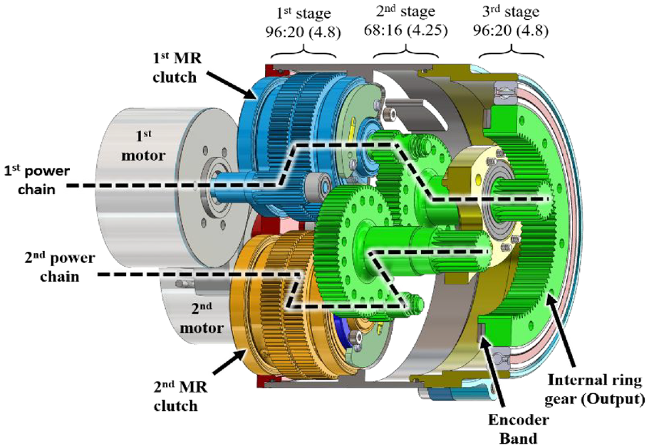
Architecture of a developed robotic join using gearing before and after MR clutches (Véronneau et al., 2022).
1.2. Background
MR clutches use MR fluid, which is composed of a carrier (i.e. oil) and micro magnetic particles (1–20 µm) (LORD Magneto-Rheological (MR) Fluid, 2015). When submitted to a magnetic field, the magnetic particles create chains that increase the viscosity of the fluid. The fluid is placed between two rotating surfaces, and the change of viscosity controls the transmitted torque from one plate to the other creating a MR clutch. The fluid is used in shear mode and the torque is controlled by the magnetic flux density across the fluid. The magnetic flux can be generated by a permanent magnet (Bucchi et al., 2014; Rizzo et al., 2015), but is often generated by a magnetic coil for fast response actuators (Fauteux et al., 2010). The shear interface can have various geometries (Nam and Ahn, 2009; Pisetskiy and Kermani, 2020; Singh et al., 2020; Wang et al., 2013) but the two main geometries are the disk type (Bucchi et al., 2017; Pisetskiy and Kermani, 2021; Shafer and Kermani, 2011b) and the drum type (Lebel et al., 2021; Qin et al., 2018; Rossa et al., 2014; Figure 3). Another type is called serpentine, and consists of one large drum where the magnetic flux crosses the same MR fluid gap several times, in a serpentine way (Blake and Gurocak, 2005; Senkal and Gurocak, 2009).
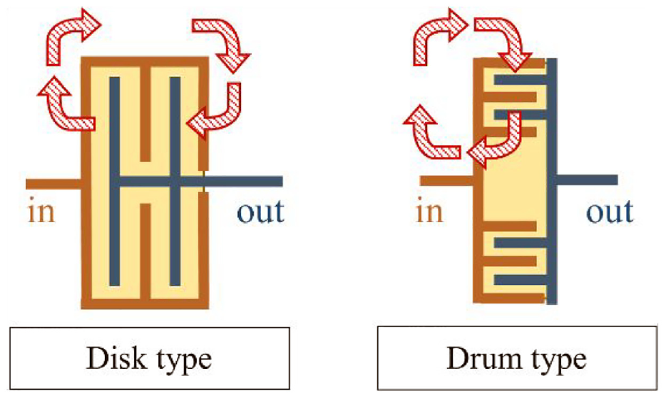
Disk and drum type clutch configuration. Red dashed arrows represent the magnetic circuit. Yellow area represents the MR fluid.
Studies show a lot of interest for torque densification of MR clutches, making them more compact (Najmaei et al., 2015; Pisetskiy and Kermani, 2020). Studies showed interest in miniaturization like Blake and Gurocak with a 68 g MR brake for haptic glove applications (Blake and Gurocak, 2009), or the one for virtual needle insertion (Gonenc and Gurocak, 2012).
Downsizing MR clutches has not been widely addressed. MR clutches and brakes are composed of many thin parts such as disks or drums, with dimensions often under the millimeter. Even if it is possible to create and machine such small parts, it becomes even more challenging to assemble them all into a reliable machine.
A possible way to overcome manufacturing limitations is to change the design and manufacturing paradigm of MR clutches to additive manufacturing (AM). In the past few years, AM has democratized significantly. Recent reviews on AM and more specifically on metal 3D printing show that a wide range of materials is now available for printing (Gadagi and Lekurwale, 2021), including stainless steel 17–4 PH, a magnetic stainless steel. Among all types of existing AM processes (Duda and Raghavan, 2016), powder bed fusion was shown very promising (Abdulhameed et al., 2019). It consists in a coater spreading fine even layers of metal powder from a powder chamber to a build chamber. Between each layer, a laser beam melts the powder where desired, so at the end of the process the melted particles form the 3D printed part (Figure 4). AM allows to dramatically reduce costs when used for small production and is very versatile (Frazier, 2014). Metal 3D printing is even starting to be used for commercial parts in a few cutting-edge fields, mainly for aerospace (Gisario et al., 2019; Tepylo et al., 2019), for example, for turbine cooling rings (Dubois et al., 2021). Metal AM can also be profitable for complex parts impossible to make with conventional machining (Shamvedi et al., 2018). An example is a reactor for hydrogen production including micro channels that enables gazes to circulate inside (Camus et al., 2019).
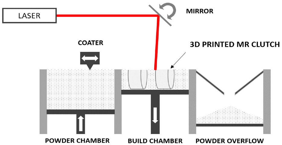
Simplified working principle of Power Bed Fusion printing process.
In the field of robot actuators, AM is already used for printing soft plastic actuators for robotic and medical applications (Zolfagharian et al., 2016). AM allows creating complex geometry configurations allowing parts to articulate and move. Even a peristaltic pump was made from a single 3D print containing nested rotating gearing (3D Printed Peristaltic Pump, 2014). In all, AM, be it metal or plastic, is opening up new possibilities for manufacturing actuators but has not been explored for MR clutches.
This paper investigates the possibility of using nested 3D printed process to fabricate miniature MR clutches. The design and manufacturing process of a fully functional prototype is presented where the spatial localization of MR shear interfaces is studied carefully to optimize the torque-to-inertia and torque-to-viscosity ratios. The performance of the prototype is then characterized experimentally to assess its torque, viscosity and inertia density as well as its controllable force bandwidth. Finally, a comparison is made with conventional machined small-scale MR clutches.
2. Analytical development
2.1. Nested 3D-printed MR clutch design
MR clutches can be composed of disks or drums separated by MR fluid interfaces where a magnetic flux passes through, as presented in Figure 3. A simple model is derived by considering a cross-sectional area covered by the stack of shear interfaces (yellow area on Figure 3), either disk or drum, as shown on Figure 5 (red hatches).
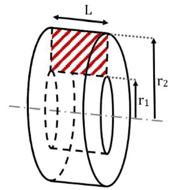
Volume of MR fluid representing a shear interface.
The volume of this element, its mass and inertia along the main axis can be expressed as follows:


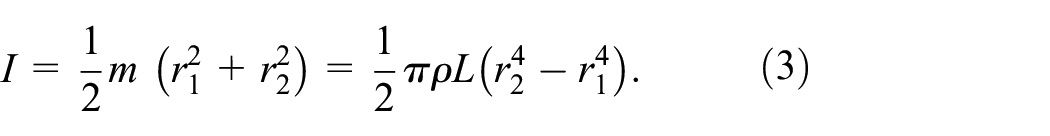
with
The number of shear interface per unit length is for disk type clutches,
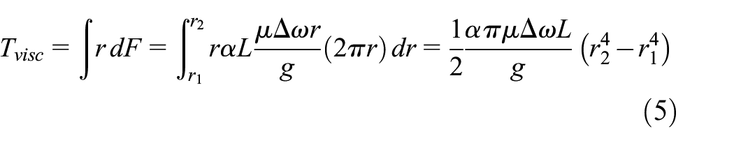
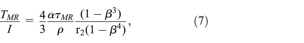
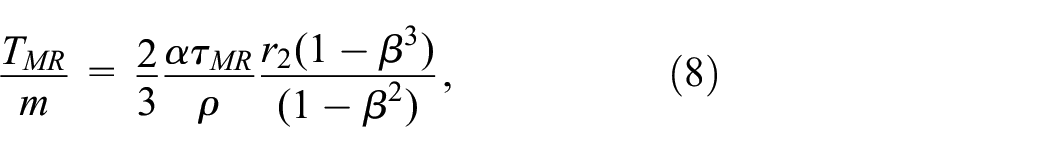
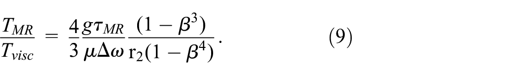
The approximated torque produced by a stack of shear interfaces contained within the element area is divided into two different components (Kavlicoglu et al., 2006). The first is the torque produced by the MR fluid when submitted to a magnetic flux, the second is the viscous torque:
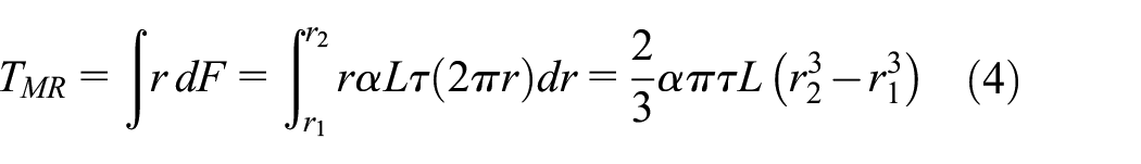
with
A form factor
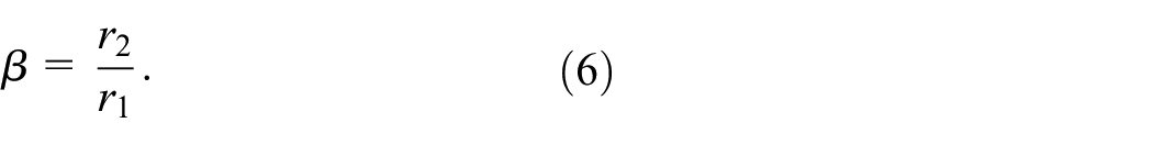
The most relevant performance metrics can be computed by comparing
The effect of
■ To maximize
■ To maximize
■
■ To maximize
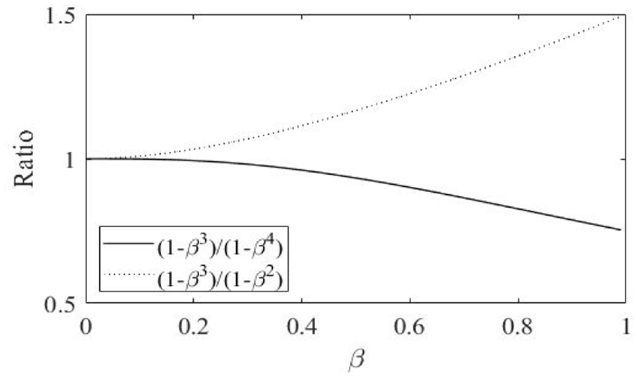
Clutch performance metrics according to
It can be concluded that to reduce inertia and viscosity, it is better to have
In addition, to further reduce inertia and viscous friction
The internal architecture of the proposed clutch design is illustrated on Figure 7. The clutch input rotor is the external disks body and the clutch output rotor is the internal disks body that is press-fitted on the output shaft. The electromagnet is supported by a non-rotating housing called outer ring. The nested 3D printing concept consists in printing the input and output rotors directly in place on a single print.

Geometrical configuration of the designed multi-disks MR clutch.
2.2. Nested 3D-printed clutch modeling
2.2.1. Geometrical analysis
MR clutches are designed for a desired maximum output torque. Torque output is estimated by considering 2
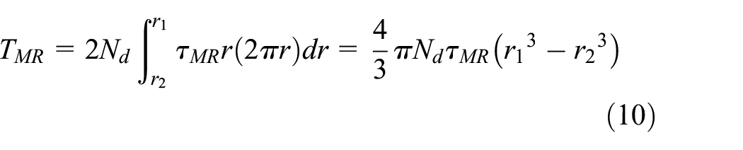
where the shear stress,
2.2.2 Magnetic analysis
An electrical analogy is proposed to determine the number of turns of copper wire needed to make the magnetic coil used to induce a magnetic field throughout the disks and MR fluid gaps. The clutch geometry is the one considered in the previous section and presented in Figure 7. The magnetic reluctance of each main portion of the magnetic circuit is considered, including reluctance of the outer ring (
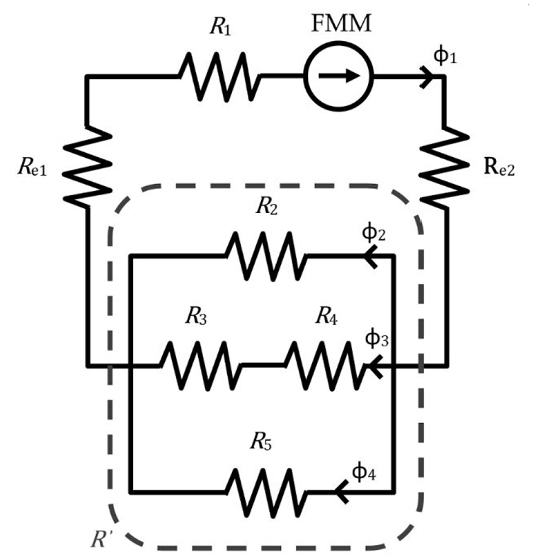
Equivalent magnetic circuit of the MR clutch.
From this equivalent circuit, we can use electromagnetic laws to find the magnetomotive force value and thus the number of turns in the coil:

with
This circuit can be simplified as shown in Figure 9 considering:

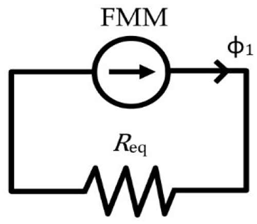
Simplified equivalent magnetic circuit.
as the equivalent reluctance of the entire circuit;
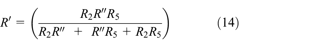
as the equivalent reluctance of

as the equivalent reluctance of
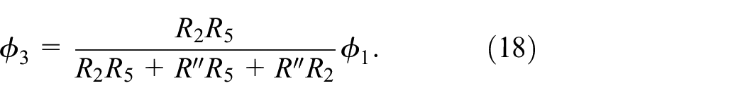
The magnetomotive force is now defined as

Knowing the desired magnetic field value in the MR fluid and the section

and thus
Gathering (12), (16), (17), and (18) gives the value of number of amp turns needed in the coil to reach the desired
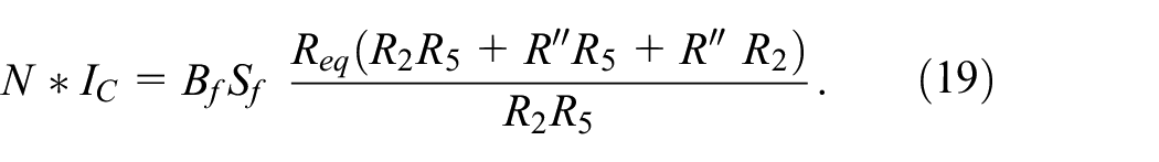
The current
From this point, all geometrical values can be set knowing the section of the coil and magnetic housing width can be designed to match a desired magnetic field density value in the steel using (17).
The reluctance of a material or a gap is defined by:
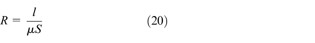
with
Eventually, there is here a trade-off to be considered knowing that a multi-disk clutch has a better torque-to-inertia and torque-to-viscosity ratios, but will need a bigger coil increasing its length thus the power consumed and the total mass of the clutch.
2.2.3. Geometry optimization with FEA
With all dimensions set, magnetic behavior is verified with FEMM, a software using Finite Element Analysis (FEA) to solve axisymmetric electromagnetic equations (Baltzis, 2008). Since all the previous computations are made with MATLAB, it is easy to couple the analysis with FEMM using Lua scripting as presented in FEMM User’s Manual (Documentation: Finite Element Method Magnetics, no date). The analysis starts by specifying the desired torque and basic geometrical parameters (disk width, MR fluid gaps, number of output disks), FEMM then computes and outputs a 2D axisymmetric magnetic field, see Figure 10. FEMM analysis results are gathered by MATLAB which fine tunes the geometrical parameters to match the desired performances set by the user. MATLAB uses field strength in shear interfaces computed by FEMM to have a better estimation of the transmittable torque. The simulations are made axisymmetric with a solver precision of 1e-8 mm, and an automatically generated mesh to allow fine mesh in the critical areas. Magnetic field limits are set to 0.75 T in the fluid, and 1.5 T in the housing at maximum current.
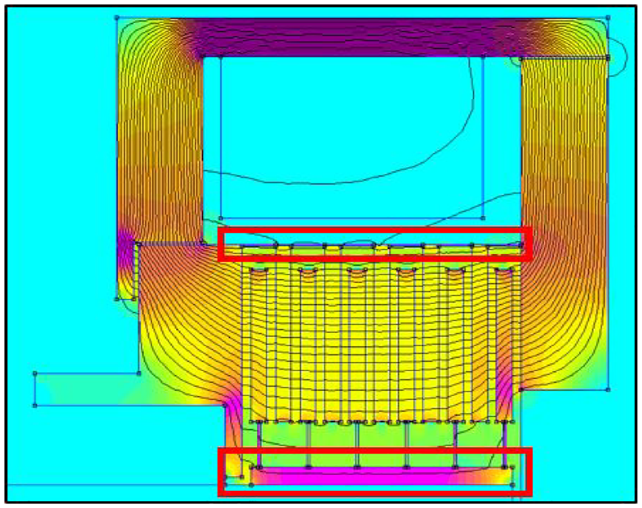
Visualization of the magnetic field and leaks (red boxes) in FEMM.
Mazeeva et al. (2020) showed that SLM (Selective Laser Melting, a power bed fusion process) was promising and competitive for printing soft magnetic materials. Mikler et al. (2017) have studied the magnetic properties of 3D printed materials and have showed that 3D printed material have comparable magnetic properties with bulk materials, but with slightly higher coercivities. It was also showed that 3D printed material contains porosities, leading to lower eddy currents compared to bulk materials (Benack et al., 2018). In first analysis, magnetic properties chosen for the 3D printed 17–4 PH Stainless Steel are taken as the same as bulk 17–4 PH and effect of porosities is neglected. The other parts of the housing parts are 1010 Steel and all non magnetic parts are either plastics or 304 Stainless Steel.
Because power bed fusion process is used to build the core of the clutch composed of the input and output rotors in a single print, these two components can only be created with a single, monolithic, material. This leads to magnetic short-circuits where the disks must be physically connected together by connecting structures, both at the inner radius of the rotor and the outer radius of the stator as shown by the red boxes on Figure 10.
In order to minimize the effect of the magnetic leaks,
Geometrical improvements to reduce magnetic leaks: (a) the outer cylinder is made of small beams and (b) output disks are linked to the shaft holder with spikes.
3. Experimental results
3.1. Prototype specifications
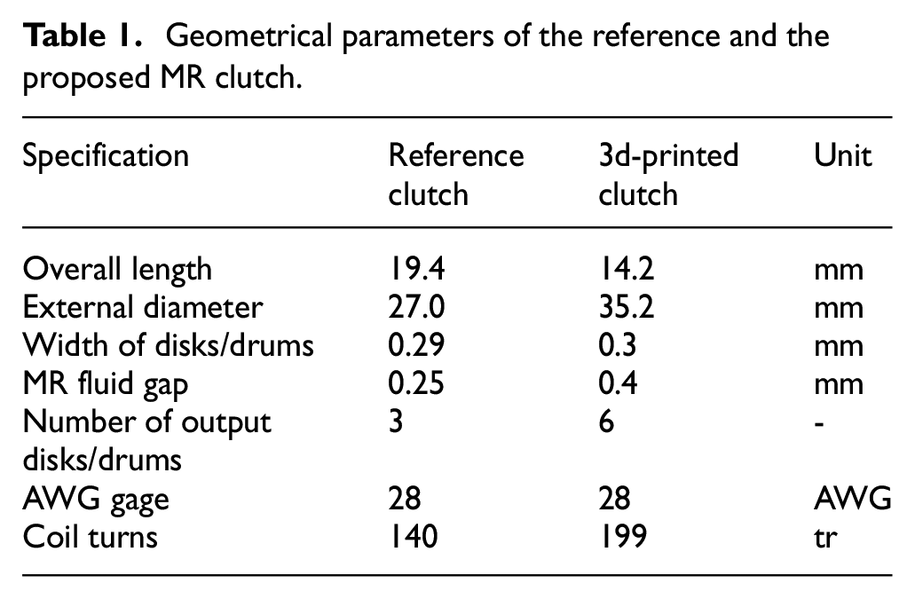
The desired output torque is set to 0.5 N.m and 28 AWG gage copper wire is selected. The geometrical analysis led to choose a 6-disk configuration visible in Figure 7, for an overall diameter of 35 mm and a height under 14 mm leading to a volume around 13 cm3. The computed output inertia (output shaft + output disks) is 102 g/mm2.
The desired magnetic field density in the MR fluid gaps is 0.75 T. A 1.3 safety factor is taken over the number of turns of the coil which is set to be 199. The result of the FEMM analysis is shown at Figure 10 and the evaluated output torque is 0.5 N.m for 2.5 A.
All measured data are compared to an equivalent drum-type MR clutch with similar mass and volume used in previous work (Lebel et al., 2021) and made with conventional machining processes. The reference clutch reaches a maximum torque of 0.4 N.m at 7 A, with a 140-turn coil of 28 AWG wire and three output drums.
The geometrical dimensions of the proposed MR clutch after optimization with MATLAB coupled with FEMM are listed in the Table 1, and compared with the equivalent conventional drum clutch.
Geometrical parameters of the reference and the proposed MR clutch.
For the 3D printed prototypes, a batch of four clutches were printed at once. The whole printing process took 9.87 h. The build plate dimensions are 100 × 100 mm which allow to print up to nine clutches on a single print. Such a full print would take 18.2 h thus reducing the print time for one clutch from 2.5 h per clutch to 2 h per clutch. Industrial 3D printers with higher capacities could print even more clutches at once. For one clutch, the human time to start and remove the print is about 20 min and the post-processing time is about 30 min per clutch (including support removal, polishing bath and machining process, see next section). The total manufacturing time for one clutch core is estimated around 2.8 h. It should be noted that all those operations were executed by a single person in a laboratory environment, so the time could decrease with proper production facilities. The overall cost for the core of the clutch, including materials and machining costs is evaluated at 85 USD. The operator cost for 0.83 h with an average 60 USD/hour represents around 50 USD, leading to a total Bill of Materials (BOM) of 135 USD for the core of the 3D-printed clutch.
The components of the reference drum clutch are all purchased from external suppliers. The total cost of the parts for one unit of the reference clutch including welding of the drums is around 310 USD. The price is high due to tight tolerances mandatory for an assembly of numerous but small parts. This price is for low volume production (1–10 pcs) and could be reduced for higher production volumes, unlike the price of the 3D-printed clutch which is less affected by production volumes. Both prices exclude tooling and assembly of the other components of the clutches.
3.2. Prototype fabrication
Because the surface finish of 3D metal printing is rough and could affect performances (Strano et al., 2013), a few machining steps are necessary before assembly with other components such as air gap fits, seals, and bearings. Thus, more material must first be placed at every surface that will require re-machining, see red the red path on Figure 12.
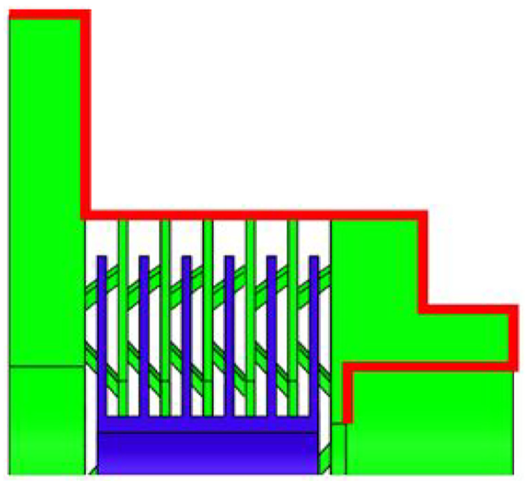
Surfaces to be machined after 3D printing process (red).
Power bed fusion process is used to print the clutch and requires a careful orientation of the parts relative to the sintering laser beam and powder rack motion direction. Part orientation will then determine how supports need to be defined (Byun and Lee, 2006). Here, the parts are printed with disks placed vertically so individual supports can be added to each of them. The support of each disk should not interfere with other volumes to be easily removable. They must be set carefully, otherwise the input and output disks could be fused together and thus unable to be separated. Weak point geometries made of triangular tips are directly set in the CAD so when the supports are bent, they break at these weak points (Figure 13(a)). Supports are defined under each surface under 45° with the horizontal (Figure 13(b)). Because the parts are re-machined, a machining support is added at the back of the clutch (Figure 13(b)), so it can easily be set in a CNC machine.
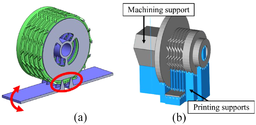
(a) Breakable supports for output disks and (b) supports generation for 3D metal printer.
The printed part is cleaned (removing all the printing supports) and set in the 3-axis machining machine with the machining support. All other parts visible on Figure 7 are also machined including the sleeve and the coil support, or 3D plastic printed pieces such as the end cap and the o-ring support. A polishing step is made in a silicate ball bath to grind disks residual defaults on disks by spinning the rotor while holding the stator fixed. A 3D scan of the disks before and after polishing is shown in Figure 14. The output disks (in orange) have a better surface finish with fewer defaults after polishing, which reduces possible interferences between input and output disks. Polishing also reduces the thickness of the output disks, thus reducing output inertia.
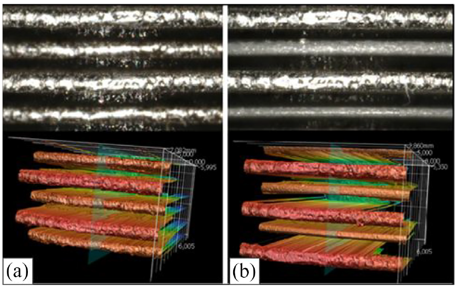
3D scan view of the disks before (a) and after (b) polishing. The output disks are the ones with the smaller radius (in orange) in the lower views.
After polishing, the clutch is assembled and filled with MR fluid (Figure 15). The final clutch assembly is visible Figure 16 with an external diameter of 35 mm and around 14 mm width.
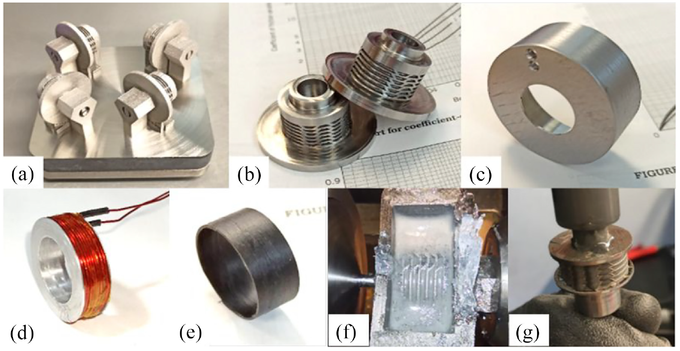
Main assembly steps: (a) 3D printed parts, (b) printed parts after machining, (c) outer ring, (d) coil on its support, (e) plastic sleeve, (f) polishing bath, and (g) MR fluid filling.
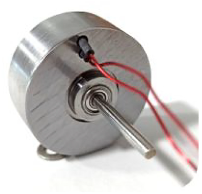
Complete MR clutch after final assembly.
3.3. Test bench design
The clutch is mounted on an experimental test bench shown on Figure 17. A power supply (model 21 A, 48 VDC) provides electrical current to two analogic drives (AMC B16A6 and 30A8T). The first drive controls a 1.05 N.m @3000 rpm brushless DC motor (HT-MOTOR 86BLF02A) with hall sensors, while the other controls the coil current (15 A in continuous mode, 30 A in peak mode). The motor is connected to the output shaft of the clutch through a 3:5 pulley ratio, and the clutch outer ring (see Figure 7). For simplicity, the clutch is tested as a brake by filling the air gap with epoxy glue allowing an easier mounting of the torque cell (Figure 18). The torque cell sends a signal that is amplified (LCA-RTC) and received by the controller (NI USD 6001 DAQ) programed with LabVIEW.
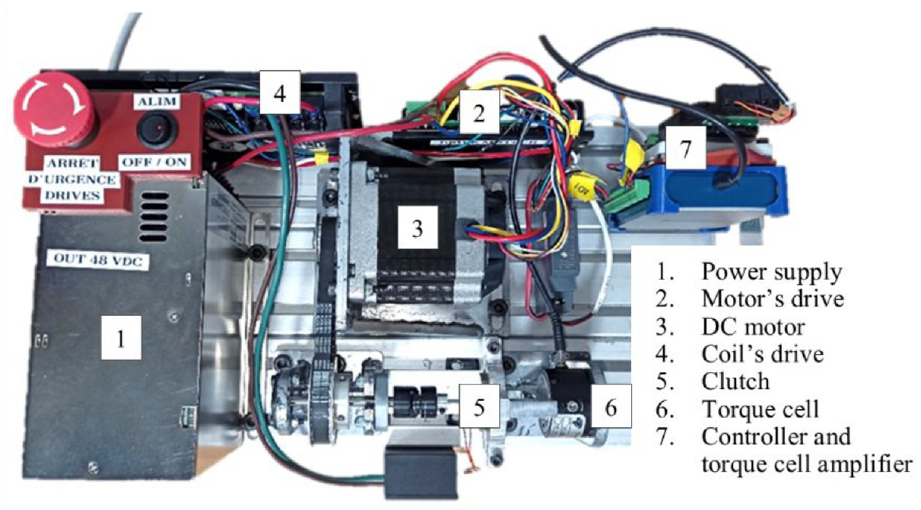
Test bench’s main components.
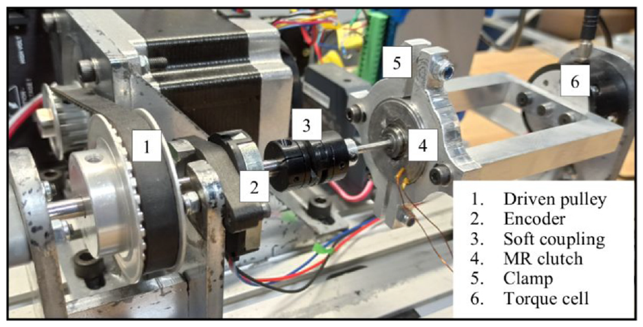
MR clutch mounted on the bench test in a clamp.
3.4. Results
Figure 19 compares the experimental characterization of the clutch with theoretically estimated results. The simulation gives a good estimation of the maximum torque of the clutch, with a slight overestimate. The computed torque value at 2.5 A was 0.5 N.m. It is seen that the experimental torque is 0.4 N.m. The maximum measured torque is 0.88 N.m at 7 A and was accurately predicted by the simulation.
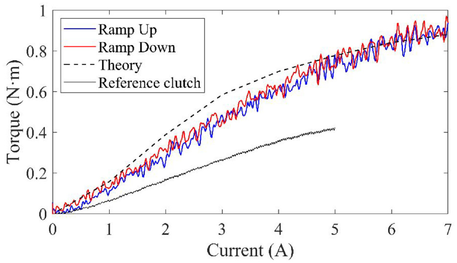
Results of the characterization of the 3D printed clutch compared to theoretical predictions and reference clutch.
The frequency response time is characterized using a chirp signal from 1 to 500 Hz. It is seen Figure 20 that the gain in amplitude is going under -3 dB at around 145 Hz, and the phase reaches −135° around 350 Hz. With command boosting, the gain limit can be pushed further (East et al., 2021) so the phase becomes the bandwidth limit (i.e. 350 Hz).
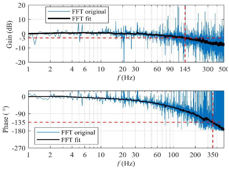
Frequency response of the 3D printed clutch to a chirp from 1 to 500 Hz.
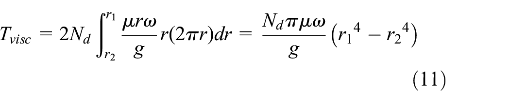
The viscous torque is characterized using a speed ramp and measuring the output torque, on Figure 21. The speed ramp starts at a value of 200 rpm up to 1500 rpm. The values are compared to the reference drum-type MR clutch. The viscous torque measured for the 3D printed clutch is about four times lower (×0.24) than the reference one. Because the two clutches do not have the same fluid inside, the reference clutch torque has been divided by its fluid viscosity and multiplied by the viscosity of the 3D printed clutch fluid to compensate for the difference. Indeed, (5) shows that the viscous torque is proportional to the viscosity of the fluid.
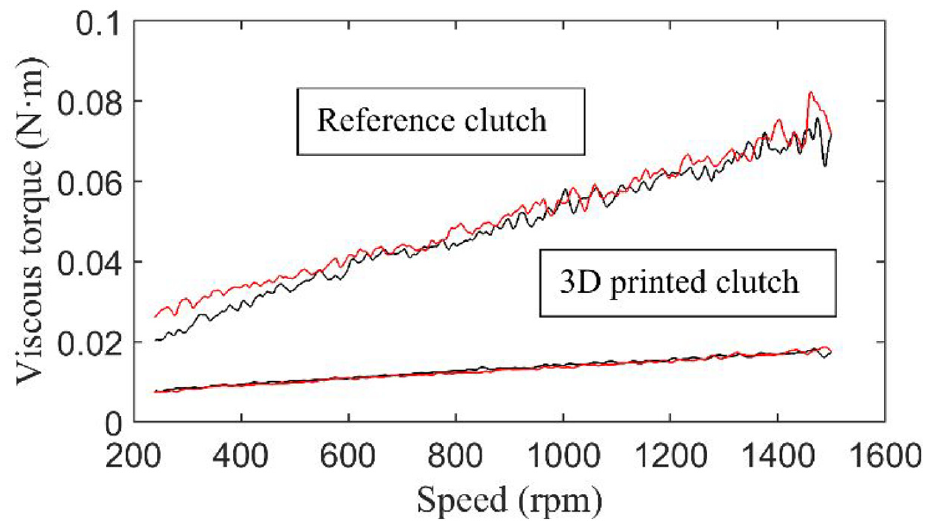
Viscous torque comparison between reference and 3D printed clutch.
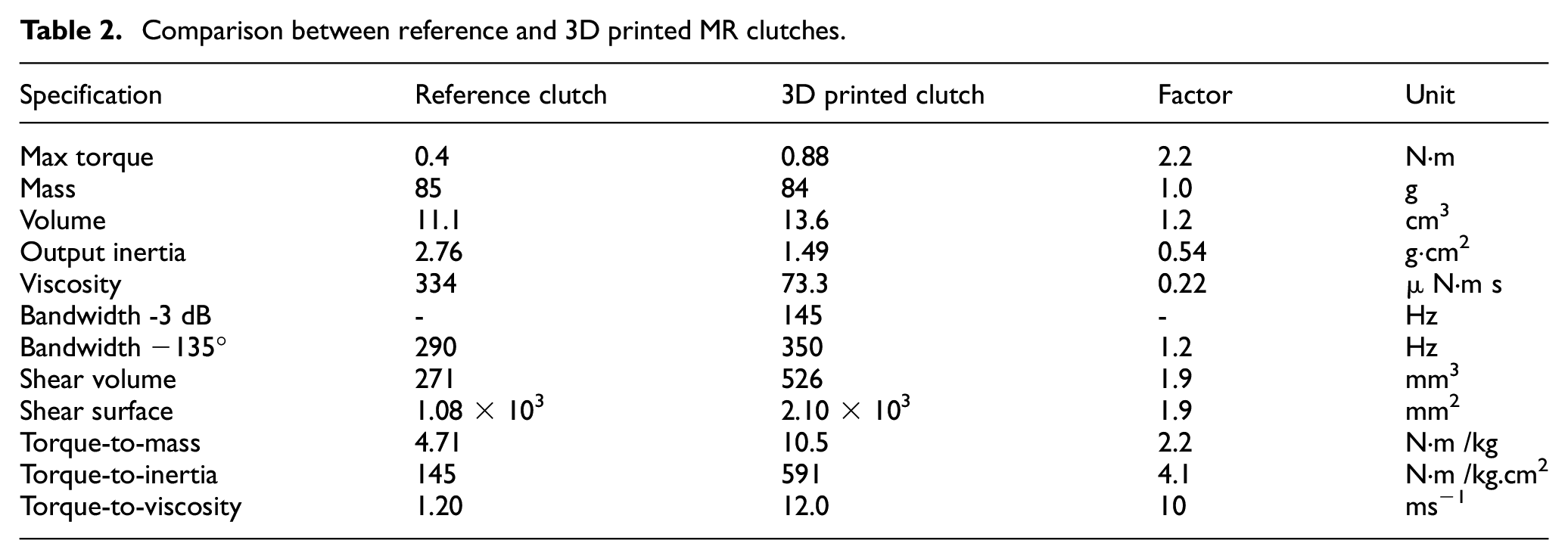
The mass of the 3D printed clutch is 84 g. The built-in settings of the 3D printer oversized all small dimensions, notably the disks, theoretically at a thickness 0.3 mm turned to a thickness of around 0.4 mm. This affects the output inertia estimations that is corrected at 149 g/mm2. All results are gathered in Table 2 for comparison.
Comparison between reference and 3D printed MR clutches.
4. Discussion
Global performances of the nested 3D printed clutch are compared with a conventional drum-type MR clutch of similar mass and dimensions in Tables 1 and 2. With a comparable mass and volume, the max torque of the 3D printed clutch is twice the reference one, whereas its output inertia is almost half. This leads to a two times higher torque density (×2.2), four times higher torque-to-inertia ratio (×4.1), and 10 time higher torque-to-viscosity ratio (×10). The higher shear volume, that is, more shear surface, of the 3D printed clutch (×1.9) can partly explicate those good results, but it also shows that the chosen configuration (i.e. long length, small radius) and manufacturing process optimize the shear volume for a given total mass. It was also shown that the 3D-printed clutch was approximately ×2 times cheaper than the conventional one.
The 3D printed clutch is also compared with similar clutches and brakes from the literature with maximum torque under 10 N.m in Table 3. It can be seen that the torque-to-inertia ratio of the designed clutch is at least 4.1 times higher than any other clutch or brake. The torque-to-viscosity ratio is also better than any other. Results show that clutch configurations as opposed to brake configurations generally leads to higher power consumption. This explains because of the presence of the two additional air gaps that increase the overall reluctance of the magnetic circuit.
Performance ratio comparison between prototyped and literature small MR clutches and brakes.
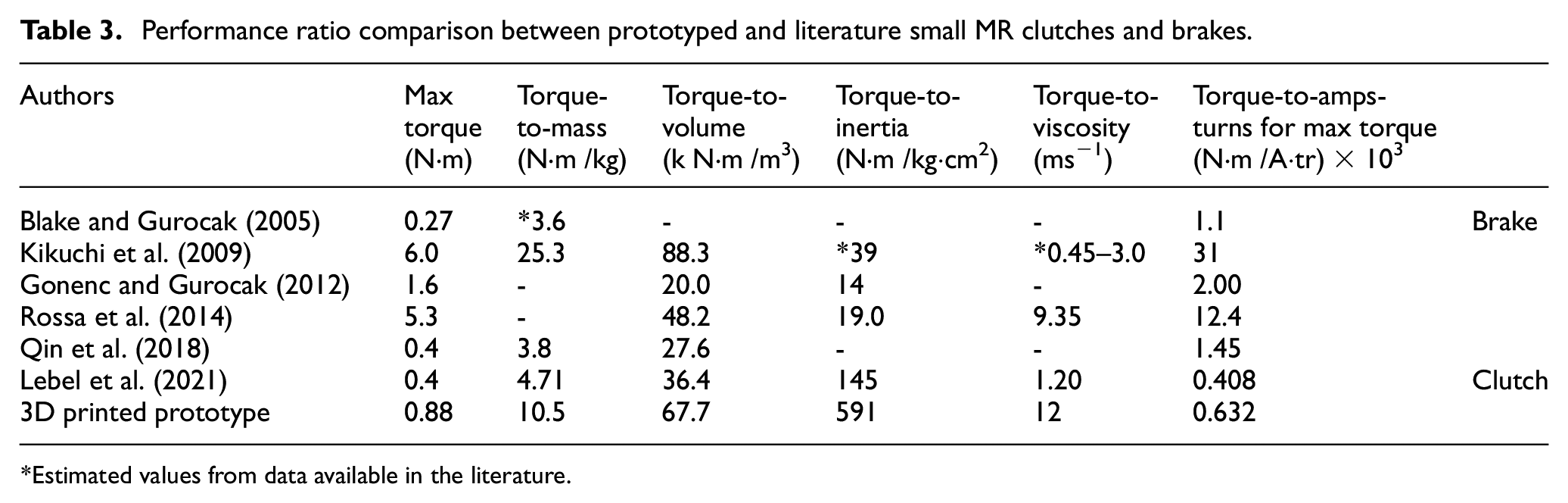
Estimated values from data available in the literature.
The significance of the performance of nested 3D printing on the overall torque density of geared MR actuators such as shown in Figures 1 and 2 is major. Lower clutch inertia and viscous friction allow to considerably increase actuator gearing, and thus reduce weight, since MR clutches are the main contributor of geared MR actuator weight. For example, assuming a geared MR-actuator with a perfect weightless, inertialess, and frictionless transmission downstream of the MR clutch, then:
■ for a same reflected inertia, actuator gearing can be increased by a factor of (4.1)0.5∼ 2x;
■ for a same viscous impedance, actuator gearing can be increased by a factor of a gearing increase up to (10.3)0.5 = 3x.
Adding the clutch torque-to-mass improvement of 2× on top of the actuator gearing improvement promises for major weight reduction potential.
5. Conclusion and perspectives
This paper studied the potential of using 3D metal printing process to design low inertia and low viscous friction small-scale MR clutches.
A metal 3D printed MR clutch has been proposed and analyzed with an analytical model validated using FEMM. The designed clutch has been built and characterized experimentally on a bench test reaching 0.88 N.m. The results fit well with the theoretical model. The prototype has a two times torque-to-mass, two times torque-to-inertia and 10 times torque-to-viscosity ratios compared with a similar reference MR clutch made with conventional machining. It has a better torque-to-inertia and torque-to-viscosity ratio than any clutch or brake from the literature under 10 N.m. It has a lightweight of 84 g, a very low output inertia of 1.49 g/cm2 and a very low viscosity of 73.3 µ N.m s, which promise excellent performances in a human-robot interaction application. The lower inertia and viscous friction of 3D printed MR clutches allow higher actuator gearing while keeping the same dynamic performance. Combined with a higher torque density, it can be concluded that nested 3D printed clutches have the potential to significantly reduce the footprint of geared MR actuators.
Although very good clutch performances have been reached, the potential of nested 3D printed clutches remains to be further studied in fully integrated geared MR actuator. Moreover, 3D metal printing still needs to be better understood in future works to exploit its full potential to minimize printed disks oversize, and it could even be used to print micro cooling channels or pumping features extending MR fluid lifetime (Pilon et al., 2020).
Footnotes
Declaration of conflicting interests
The authors declared no potential conflicts of interest with respect to the research, authorship, and/or publication of this article.
Funding
The authors disclosed receipt of the following financial support for the research, authorship, and/or publication of this article: this work was supported by NSERC Discovery Grant with Acceleration Supplement, the Canada Research Chair Program and Mitacs Accelerate program.