
Abstract
The article details experimental work to evaluate tool wear, cutting forces/torque and associated hole quality/accuracy following single-shot drilling of twin layer CFRP/AA7010 stacks. A full factorial experiment was initially planned involving variation in cutting speed (60 and 120 m/min), feed rate (0.15 and 0.30 mm/rev) and drill tip geometry (double cone and flat point drills). While flank wear for the flat point drills did not exceed 40 µm even after 120 holes irrespective of operating conditions, the double cone geometry suffered catastrophic failure after only four holes at the lowest parameter combination. Therefore, the remaining tests involving the double cone drill at higher operating parameters were subsequently halted. Feed rate had a significant influence on torque in both the CFRP and Al layers, although thrust force and torque generally remained stable over the test duration. Hole diameter was typically up to 34 µm above the nominal value of 6.38 mm with corresponding out of roundness of <60 µm. Burrs were prevalent at hole exit in all tests, with an average height of ∼120 µm when drilling at the highest cutting speed–feed rate parameter combination. Similarly, the delamination factor at hole entry increased by up to 23% when operating at the higher feed rate level.
Introduction
The design of modern civil aircraft over the last decade has incorporated greater use of multilayer stack materials comprising carbon fibre–reinforced plastic (CFRP) composites (up to ∼50% weight) together with aluminium (Al) and/or titanium (Ti)-based metallic alloys. These are mainly employed in high-load bearing sections, in particular the joints between the wings and fuselage. The joining of such structures is primarily realised through mechanical fastening and therefore, the process of hole production to the appropriate quality is a key consideration. Due to the vastly different mechanical/physical properties of the composite and metallic layers, current industry practice for drilling stacks generally involves three or more operations in order to achieve required hole tolerances. 1 However, the rising worldwide demand for new airplanes coupled with the continuous drive towards reducing machining cycle time, costs and hole alignment errors during assembly has led to the development of single-shot drilling technology as well as increased utilisation of process automation.2,3
Research involving single-shot drilling has predominantly focussed on two-layer stacks encompassing either CFRP/Al 4 or CFRP/Ti 5 alloy arrangements, with only a limited number of publications reporting work on three-layer Ti/CFRP/Al configurations.6,7 Zitoune et al. 8 compared the performance of uncoated tungsten carbide (WC) double cone geometry tools against conventional twist drills when drilling CFRP/AA2024 stacks at varying cutting speeds (40 and 55 m/min) and feed rates (0.05, 0.10 and 0.15 mm/rev). It was found that thrust forces typically decreased by 15%–30% in the CFRP layer and by up to ∼10% in the Al section when employing the double cone drill, although no details of tool wear/life were reported. This was attributed to the presence of a 90° secondary point angle, which reduced the theoretical chip thickness by 15%. Furthermore, increasing feed rate to ≥0.10 mm/rev using the double cone drill induced the formation of smaller aluminium chips, thereby minimising damage to hole surfaces in the CFRP layer. Similarly, a twin cutting edge drill design was shown to outperform standard twist drills when machining 6.17-mm-thick CFRP/AA7075 stacks in terms of lower thrust forces (∼20%), superior hole accuracy and up to a ∼50% decrease in roughness of the CFRP section. 9 This was partly due to the shorter chisel edge length and better self-centring capability of the twin cutting edge drill.
The use of coated WC drills is generally recommended for its greater resistance to abrasion when drilling CFRP-based materials. In trials involving CFRP/AA2024 stacks, drills coated with a nanocomposite coating containing nanocrystalline CrAlN together with amorphous Si3N4 demonstrated reduced thrust forces of up to 25% and 47% in the CFRP and Al sections, respectively, together with improved CFRP hole surface roughness, when compared to equivalent uncoated tools. 10 Likewise, diamond-based coatings were found to exhibit considerably slower flank wear rates (∼120 µm as opposed to ∼250 µm for uncoated drills after 250 holes) when drilling CFRP/AA7010 stacks. 11 An alternative to coated WC for drilling CFRP/Al stacks is veined polycrystalline diamond (PCD) tools, which are reportedly capable of maintaining consistent hole dimensional accuracy (deviation ≤ 5 µm from nominal diameter), with no obvious signs of exit burr formation even after 30 holes, 12 albeit at the expense of substantially higher drill costs. The present work aims to investigate the performance of two different drill tip geometries when single-shot drilling CFRP/Al stacks at elevated cutting parameters to address the increasingly stringent hole quality requirements in the aerospace industry.
Experimental work
Workpiece material, drills, equipment, test setup and procedures
The workpiece material was two-layer stacks consisting of CFRP and AA7010-T7451 aluminium alloy, which were mechanically joined using socket head countersunk (CSK) screws (M4 × 12 mm). The CFRP comprised 40 unidirectional (UD) prepreg layers (each with a thickness of 0.25 mm) composed of intermediate modulus carbon fibres (average diameter of 6 µm) impregnated within an epoxy matrix. The prepregs were laid up according to a laminate configuration of [45/135/0/0/45/135/0/0/90/0/45/135/0/0/45/135/0/0/90/0]S together with a 0.06-mm-thick glass fibre–reinforced plastic (GFRP) top ply (glass fibre fabric prepreg type M21/1080), which was subsequently autoclave cured to provide a tensile strength and modulus of 1550 MPa and 97 GPa, respectively. Aside from functioning as a protective layer for the CFRP laminate during the curing process, the GFRP top ply has also been shown to assist in minimising the initiation/propagation of hole edge damage such as delamination, fuzzing and spalling during drilling operations. 13 The AA7010 aluminium alloy was solution treated, water quenched and aged followed by controlled-stretching, resulting in tensile strength of 525 MPa and corresponding Young’s modulus of 71.7 GPa. The stacks were supplied in the shape of square plates measuring 150 × 150 × 16.5 mm for tool life trials and in the form of strips having dimensions of 120 × 17 × 16.5 mm, which were utilised for thrust force/torque measurements and hole quality/integrity analysis. Two different drill tip geometries involving a double cone and flat point design were evaluated, see Figure 1, both having dual point angles with details outlined in Table 1. Both of the solid WC drills were twin fluted and chemical vapour deposition (CVD)-diamond coated with a nominal hardness of 8000–10,000 HV.
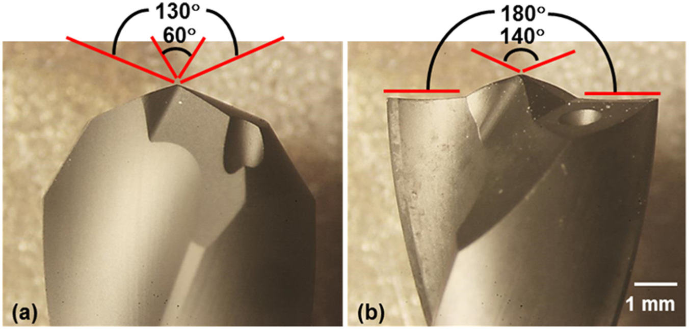
Micrographs of (a) double cone geometry and (b) flat point geometry drills.
Geometry of the different drill tips.
All tests were carried out on a Matsuura FX-5 CNC high-speed machining centre having a maximum spindle speed of 20,000 r/min rated at 15 kW. Thrust force and torque were measured using a Kistler 9273 piezoelectric dynamometer connected to model 5011A charge amplifiers after the first hole followed by intervals of 20 holes drilled, with the signals transmitted to a PC installed with DynoWare software for data acquisition and analysis. Drill flank wear was measured using a WILD M3Z toolmakers microscope equipped with a digital micrometre platform together with a mounted digital camera to capture images of new and worn tools. The maximum flank wear on each flute was measured three times with the results averaged. A Mitutoyo coordinate measuring machine (CMM) with a 2 mm diameter ruby ball stylus was employed to assess hole diameter and out of roundness by sampling 24 points at each of the five pitch planes specified in the hole (at distances of 2, 5, 8, 12 and 14.5 mm from hole entry), which were subsequently averaged. An Alicona InfiniteFocus G5 system was utilised to obtain micrographs of the hole entry surface on the CFRP layer and generate three-dimensional (3D) images of the entry and exit burr geometries in the Al layer (following disassembly of the strip specimens). The height of the burrs was determined from four equally spaced positions around the hole circumference. Optical cross-sectional micrographs of burrs were also taken using a Leica metallographic microscope. The Alicona unit was similarly used to measure the maximum damage and nominal diameter of the holes on the CFRP surface in order to calculate the corresponding delamination factor.
A full factorial experiment was designed involving three variable factors (drill geometry, feed rate and cutting speed), each at two levels as shown in Table 2. While the drilling conditions employed were higher than those recommended by the tool manufacturer, there was no attempt to optimise the cutting parameters as this was beyond the scope of the current investigation. The end of test criteria was an average maximum flank wear of 300 μm (over both flutes) or 120 holes drilled. All of the trials were performed under a chilled air environment (temperature of ∼5°C) supplied by a vortex tube system via twin nozzles, see Figure 2 for experimental setup.
Experimental array.
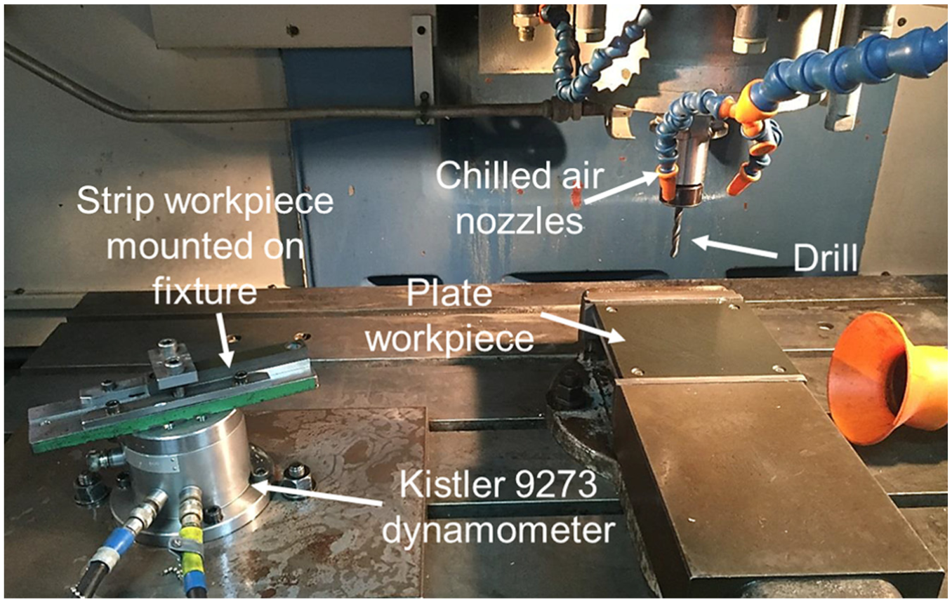
Experimental setup on Matsuura FX-5.
Results and discussion
Tool wear/life, thrust force and torque
The double cone drill in Test 1 (lowest cutting speed and feed rate combination) experienced catastrophic fracture after drilling only four holes. Analysis of the thrust force and torque traces recorded when drilling the first hole revealed considerable fluctuations in both signals especially for the Al layer of the stack, see Figure 3. In particular, the average torque (∼122 N cm) generated in the Al section was considerably greater (by ∼70%) when compared to the trial with the flat point drill at equivalent conditions (Test 2 – results shown later). This was due to poor evacuation of the continuous Al swarf as well as subsequent material adhesion and packing of drill flutes in Test 1. The folded chips consequently led to tool jamming as the test progressed and eventually failure of the drill. This suggests that the double cone drill was unsuitable for dry drilling of CFRP/Al stacks using the present operating parameter window, and therefore, the remaining trials involving this tool geometry (Tests 3, 5 and 7) were abandoned. Trapped material and inadequate removal of chips from the cutting zone have previously been highlighted as a key cause of tool breakage in drilling operations. 14
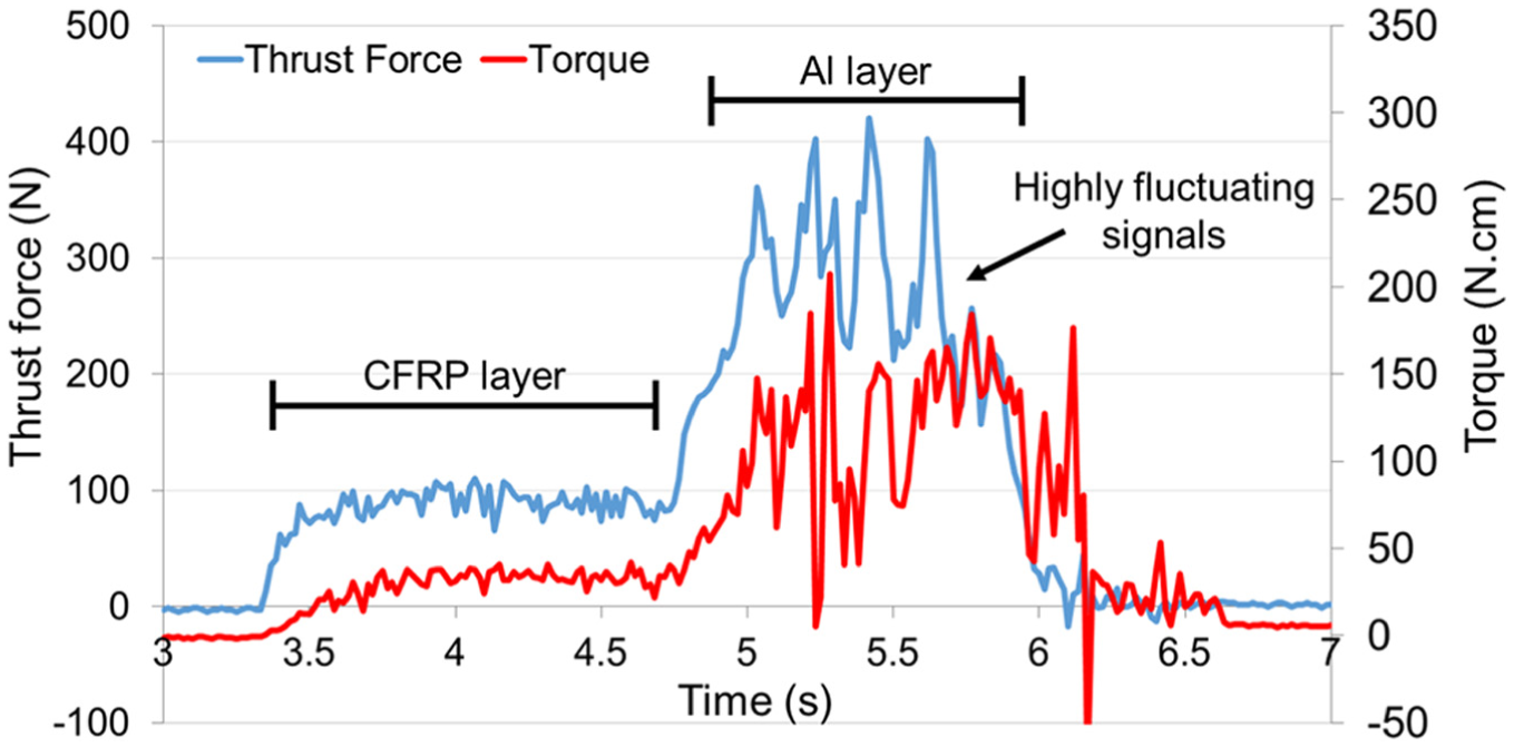
Thrust force and torque signature of the first hole in Test 1.
Figure 4 shows the progression of average maximum flank wear in tests involving the flat point drills (Tests 2, 4, 6 and 8). Flank wear levels on all of the drills did not exceed 40 μm even after drilling 120 holes. The wear rate for trials performed at 0.15 mm/rev (Tests 2 and 6) however was marginally higher compared to those undertaken at 0.30 mm/rev (Tests 4 and 8), which was likely due to the longer contact time between the drill and stack workpiece when operating at the lower feed rate. A similar response to changes in feed rate has been reported when drilling CFRP. 15 Furthermore, the wear mechanism was primarily uniform abrasion, with no signs of cutting edge fracture or micro-chipping on any of the drills, see examples in Figure 5.
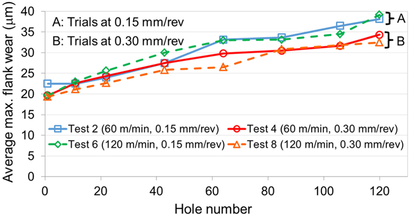
Flank wear progression of flat point drills.
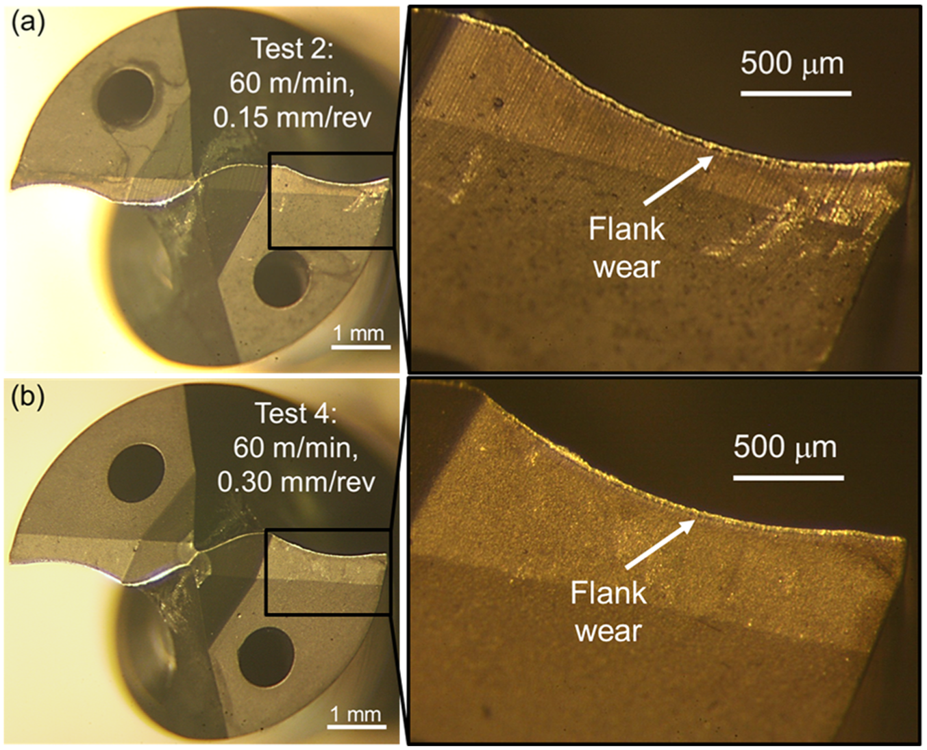
Example of drill flank wear after 120 holes in (a) Test 2 and (b) Test 4.
The average thrust force and torque with respect to the number of holes drilled in the CFRP and Al layers is detailed in Figure 6. In all cases, both the thrust force and torque values were largely stable over the test duration, which was likely attributed to the relatively low amount of wear on the drills. However, a gradual decreasing trend in thrust forces was evident in the Al section with increasing number of holes drilled, possibly due to rising temperature and subsequent material softening as the trials progressed. The reduction in cooling efficiency of the chilled air as the drill moved deeper into the holes (Al layer) may also have been a contributing factor. In terms of cutting parameters, increasing feed rate from 0.15 to 0.30 mm/rev led to higher thrust forces and torque in both layers of the stack by up to ∼100% and ∼60%, respectively, while variation in cutting speed had negligible influence. This trend was also observed in trials involving the drilling of CFFP/Ti-6Al-4V stacks. 16 Analysis of variance (ANOVA) also highlighted that feed rate was statistically significant at the 5% level with respect to torque in both materials.
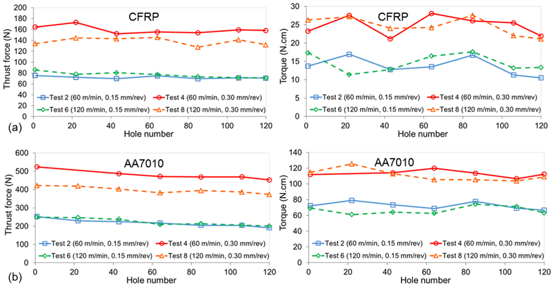
Thrust force and torque against number of holes drilled in the (a) CFRP and (b) AA7010 layer of the stack.
Hole dimensional accuracy
The average diameter of the first and last holes machined in tests utilising the flat point geometry drills is shown in Figure 7. Apart from the last hole in the CFRP layer from Test 4, all of the holes analysed were between 6 and 34 μm above the nominal diameter of 6.38 mm, which was within a H9 tolerance zone. Further inspection of the results indicated that the majority of holes produced under the higher feed rate of 0.30 mm/rev in Tests 4 and 8 exhibited superior diametrical accuracy corresponding to a tolerance of H7, with deviations not exceeding 15 μm. This may have been due in part to the higher thrust forces generated, which acted to minimise any effect of lateral/radial instabilities. The associated ANOVA also showed that feed rate had a dominant influence on resulting hole diameter and was statistically significant at the 5% level with respect to the Al section, with a percentage contribution ratio (PCR) of ∼95%. In general, hole diameter in Al was marginally larger than the CFRP layer, as the former has a lower modulus of elasticity and higher thermal expansion compared to the latter. 17
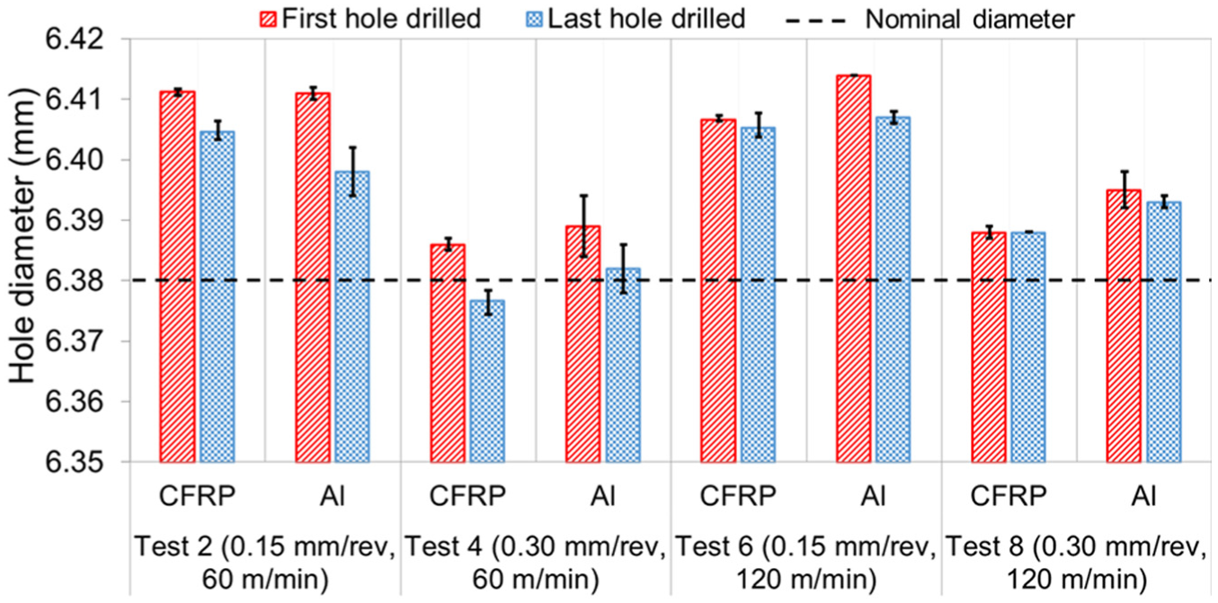
Hole diameter for first and last holes drilled.
Out of roundness of the first and last holes drilled in the CFRP and Al layers for each test are detailed in Figure 8. Average out of roundness was below 50 μm in all of the holes assessed, with values in the CFRP layer generally larger than the Al section. This was possibly due to tool runout causing radial deflection or initial chisel edge sliding (also known as ‘walking’) as the drill penetrated the top CFRP layer, which was observed by Kuo et al. 7 when single-shot drilling three-layer Ti/CFRP/Al stacks. However, as the drill moved deeper into the stack, the hole wall acted to minimise tool eccentricity, thus reducing the hole out of roundness. In any case, none of the variable factors were found to be statistically significant according to the ANOVA for hole out of roundness.
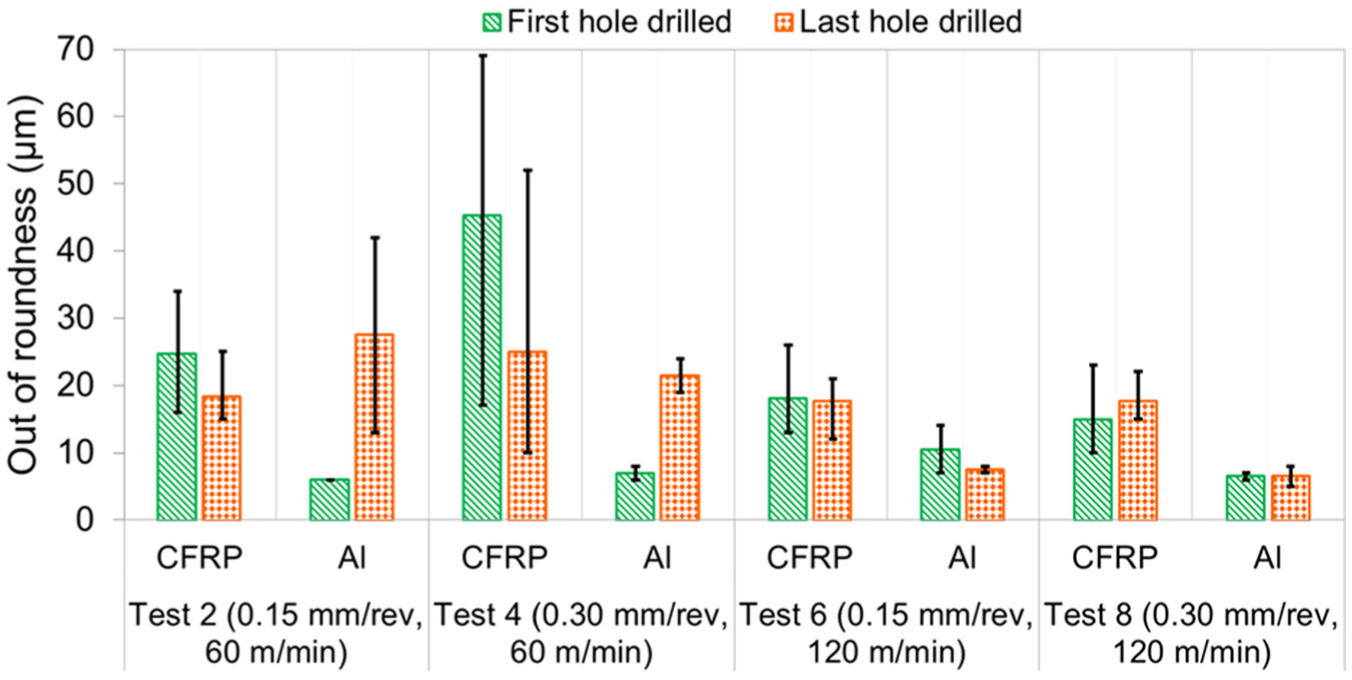
Hole out of roundness for first and last holes drilled.
Burr formation
Measurements of the entry/interlayer and exit burr height together with exit burr width for the first and last holes machined in the Al layer are shown in Figure 9. The average entry/interlayer burr heights were relatively small and ranged from ∼15.3 to 32.5 μm, with the CFRP section providing support in restricting growth of the burrs. Conversely, average exit burr height was at least two times larger than those at the interlayer position, which varied from ∼60 to 120 μm and was approximately equivalent to the width of the burrs (∼70–119 μm). All of the burrs however were generally uniform around the circumference of the holes, as illustrated by the selected 3D image and associated cross-sectional micrograph shown in Figure 10. In general, both the exit burr height and width increased with feed rate, while average exit burr height was observed to be somewhat smaller with increasing number of holes drilled when operating at the higher feed rate level (Tests 4 and 8).
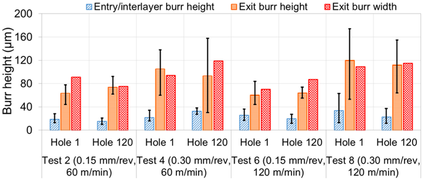
Burr height and width for first and last holes drilled.
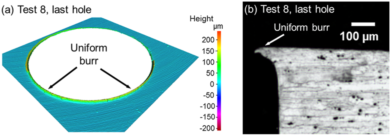
(a) Three-dimensional image and (b) cross-sectional micrograph of uniform burr formation for last hole drilled in Test 8.
Delamination
No signs of any obvious delamination were evident at the CFRP hole exit in any of the tests, which was principally attributed to backing provided by the bottom Al layer, similar to that reported by Isbilir and Ghassemieh 18 when drilling CFRP/Ti-6Al-4V stacks. Figure 11 details the entry delamination factor for the first and last holes drilled, which varied between ∼1.18 and 1.51 over the range of experiments conducted. In general, the delamination factor was found to increase by up to ∼23% when employing the higher feed rate (0.30 mm/rev), which was largely due to the greater thrust forces generated. This was further evidenced by more severe damage in the form of uncut/frayed fibres that was visible even in the first hole for Tests 4 and 8, see Figure 12. In contrast, the effect of cutting speed and tool wear/number of holes drilled was negligible.
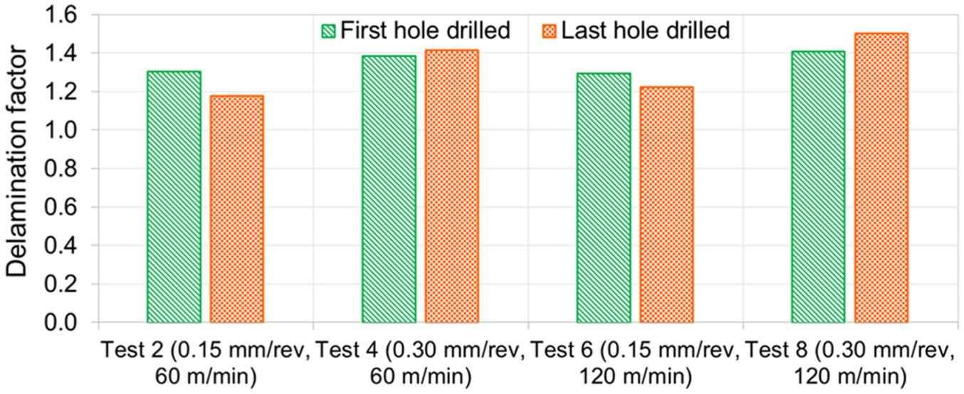
Entry delamination factor in CFRP for first and last holes drilled.
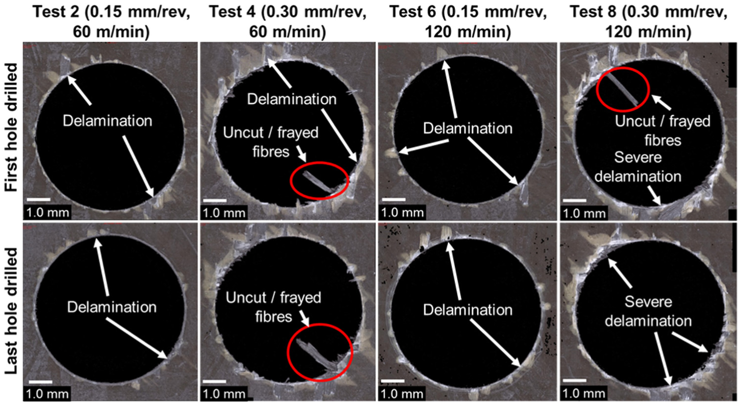
Micrographs of hole entry damage in CFRP for first and last holes drilled.
Conclusion
The double cone geometry drill was found to be inappropriate for single-shot drilling CFRP/Al stack configurations, which failed catastrophically after only four holes even when operating at the lowest parameter combination. This was caused by severe packing/adhesion of chips in the drill flutes that hindered subsequent swarf evacuation from the hole.
Flank wear of the flat point geometry drills did not exceed 40 μm in any of the trials even after 120 holes, regardless of the operating conditions.
Feed rate within the range tested was found to have a dominant effect on drill flank wear, thrust force/torque, hole dimensional accuracy, burr formation and delamination, but was only statistically significant at the 5% level with respect to torque (in both layers of the stack) and hole diameter of the Al layer.
All of the holes evaluated had diameters varying between 6 and 34 μm above the nominal value, which was within a tolerance of H9. Increasing feed rate led to an improvement in hole accuracy with diameter deviation not exceeding 15 μm.
Exit burrs on the Al section were predominant in all of the holes analysed, with average heights of 60–120 μm. These contrasted significantly with the entrance burrs which were substantially smaller at ∼15–33 μm, due to the presence of the top CFRP layer.
Drilling at the higher feed rate (0.30 mm/rev) induced greater damage at the entrance location of the hole in the CFRP layer, which included uncut or frayed fibres together with increased delamination factors of up to ∼23%.
Footnotes
Declaration of conflicting interests
The author(s) declared no potential conflicts of interest with respect to the research, authorship and/or publication of this article.
Funding
The author(s) received no financial support for the research, authorship and/or publication of this article.