
Abstract
Wire electrochemical micromachining is a promising micromachining method of fabricating micro metal parts. Before conducting wire electrochemical micromachining, microwire electrode should be prepared. Existing microwire electrode preparation processes suffer from drawbacks such as inconvenience in remounting the fabricated electrode and losses of accuracy and efficiency as the electrode is moved for the subsequent wire electrochemical micromachining. Dynamic liquid membrane electrochemical etching of a microwire electrode is proposed here as a way to overcome these limitations by in situ fabrication of the electrode. A mathematical model is constructed to predict the diameter of the fabricated microwire electrode and experimental results are in good agreement with the model. An experimental setup is developed combining the functions of electrode fabrication and wire electrochemical micromachining. Microwire electrodes with the diameter of 14 μm have been prepared, and microslits with the width of 34 μm have been fabricated without the need to remount the electrode.
Keywords
Introduction
The development of product miniaturization has led to an ever-growing demand for the fabrication of complex microfeatures by various industries, including those concerned with aerospace, biomedicine, automobile manufacture, healthcare, and consumer electronics.1,2 Micromachining techniques are essential in the manufacture of such microfeatures. Among these techniques, electrochemical machining (ECM) is an electrochemical dissolution process that can remove electrically conductive materials regardless of their hardness and toughness. 3 ECM has its specific advantages such as no tool wear, mechanical forceless machining, no thermally influenced machining zones, high surface quality, low roughness, and stress-free surface products. 4 ECM and its hybrid processes such as pulse-assisted ECM and ultrasonically assisted electrochemical micro drilling have become promising machining processes in the industrial applications.5,6 Wire electrochemical micromachining (WEMM) shares the basic characteristics of ECM and can be applied to fabricate microstructures such as microgrooves and microtrenches. 7 In WEMM, a pulsed voltage is applied between the workpiece and a wire electrode. As the wire electrode moves toward the workpiece (which acts as the anode), material is electrochemically removed from the latter, with the creation of a narrow slit. WEMM can produce a smooth and burr-free surface. 3 In contrast to wire electrical discharge machining, the wire electrode does not wear away, which allows the use of a thinner wire of micrometer or even submicrometer scale. 8 Thus, WEMM is a promising micromachining technique for the manufacture of smaller-dimensional microcomponents or microsystems. 3
Generally, both the machining precision and the minimum scale of the processed microfeatures achievable depend mainly on the diameter of the microtool electrode. 9 In WEMM, reducing the diameter of the wire electrode plays a decisive role in decreasing the machining side gap, that is, improving the machining accuracy of WEMM. 10 The preparation of wire electrodes with smaller diameters is therefore an essential requirement for improving the WEMM technique. However, wire electrodes of micrometer scale are easily deformed and are difficult to fix onto a machining system with high accuracy, and so the in situ preparation of such microtool electrodes remains a great challenge.
Microtool electrodes have been fabricated using a variety of manufacturing processes, such as micromechanical machining, 11 wire electro-discharge grinding, 12 a localized electrochemical deposition process, 13 and ECM. 14 Alok and Partha 15 utilized a micro-electrochemical form-turning operation to fabricate cylindrical micro-electrodes of diameter of 50 μm. To minimize the influence of geometry, electrically nonconductive material had to be coated on both ends of the anode electrode, which was time-consuming and technically difficult to do. Wang et al. 10 fabricated microwire electrodes of diameter of 10, 5, and 2 μm in situ and used them for WEMM. In their experiments, an initial wire electrode was placed for dissolution in the center of a stainless steel barrel, which was filled with sodium hydroxide (NaOH) solution. After electrochemical etching was completed, the stainless steel barrel was replaced by another container filled with hydrochloric acid (HCl) solution, since the WEMM was to be performed in an acidic environment. The need to alter the position of the microwire electrode between the different stages led to a great deterioration in the accuracy and efficiency of the WEMM. Thus, there is an urgent need for a method that allows the fabrication of the wire electrode and the subsequent WEMM process to be performed in a single system.
This article describes an attempt to fabricate a microwire electrode using dynamic liquid membrane electrochemical etching in which a linear reciprocating motion is applied to the anodic rod. Using this method, the anodic rod is machined periodically within the amplitude of the reciprocating motion, ultimately producing a microwire electrode. This electrode can then be used immediately for WEMM. A mathematical model is constructed to predict the diameter of the wire electrode. Experiments are conducted to verify the validity of the proposed method and the mathematical model. Finally, the prepared microwire electrodes are used successfully in WEMM for fabricating microgrooves.
Principle of the proposed method
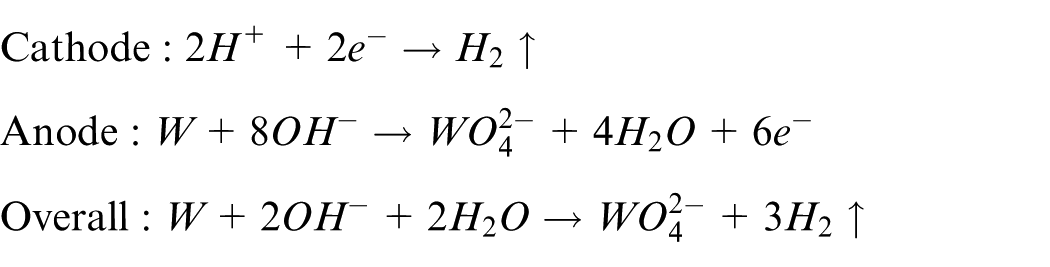
A schematic illustration of the in situ fabrication of a microwire electrode using dynamic liquid membrane electrochemical etching is shown in Figure 1. A tungsten ring is employed as the cathode and a tungsten rod of diameter of 300 μm as the anode. The electrolyte is a potassium hydroxide (KOH) solution, which forms a liquid membrane suspended on the tungsten ring as a result of surface tension. A clamp of wire electrode is introduced, which is connected to the Z-axis positioning stage. Two copper tubes, both of inner diameter of 300 μm, are fixed firmly at the upper and lower parts of the clamp. The tungsten rod is passed through these tubes and positioned at the center of the liquid membrane. When a direct current (DC) voltage is applied between the anode and cathode, the following electrochemical reactions occur at the cathode and anode
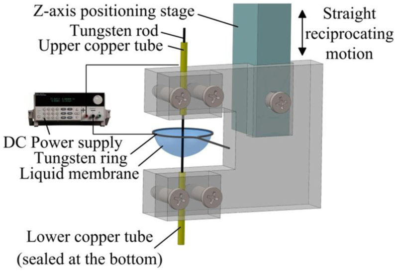
Schematic illustration of the in situ fabrication of a microwire electrode by dynamic liquid membrane electrochemical etching.
To fabricate the microwire electrode, a linear reciprocating motion is applied to the anodic rod in the vertical direction, so that the region of the rod exposed to electrolyte and thus subjected to machining alternates periodically. This provides an approximately uniform reduction of the diameter of the rod within the amplitude range of the reciprocating motion. When the required diameter has been achieved, the electrolyte is absorbed by a filter paper and the tungsten ring is cut off to leave the microwire electrode. The key issue of controlling the diameter of a microwire electrode produced in this manner is addressed by constructing a dynamic mathematical model of liquid membrane ECM with linear reciprocating motion of the wire electrode.
Mathematical model
Wu et al. 16 have previously constructed a static model of liquid membrane electrochemical etching of a nano-tip. However, their model did not consider the cylindrical region produced as a result of the reciprocating motion of the rod. It is therefore necessary to extend the model to take account of the effects of reciprocating motion.
To aid in the construction of such a model, the following simplifying assumptions are made:
The conductivity of the electrolyte remains constant.
The consumption of electrolyte is negligible.
The region of the tungsten rod within the amplitude of reciprocating motion retains the shape of a uniform cylinder during the whole etching process.
As shown in Figure 2, the etched rod is divided into three parts:
Part 1: the upper part of the rod which is etched by the meniscus;
Part 2: the middle part of the rod which is immersed in electrolyte within the amplitude of the reciprocating motion;
Part 3: the lower part of the rod which shapes like a reverse cone due to increasing diffusion layer thickness. 17
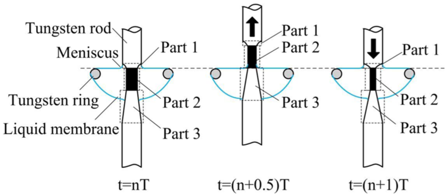
Schematic illustration of reciprocating motion.
Figure 2 illustrates a cycle of the reciprocating motion with the diameter of the cylindrical part decreasing as etching continues.
The period of the reciprocating motion can be expressed as
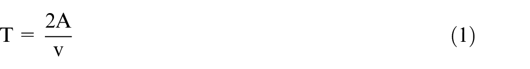
where
When t = nT, part 1 contacts with the meniscus formed above the ring, part 2 contacts with the liquid membrane; some of part 3 contacts with the liquid membrane.
When nT < t < (n + 0.5)T (the rod is going up), part 1 is leaving the meniscus and part 2 is passing through the meniscus. The length of part 3 soaking in the liquid membrane is increasing.
When t = (n + 0.5)T, part 1 and most of part 2 are exposed in air, a small section of part 2 contacts with the meniscus, and the whole part 3 contacts with the liquid membrane.
When (n + 0.5)T < t < (n + 1)T (the rod is going down), part 1 is getting close to the meniscus and finally immersed in the meniscus. Part 2 is passing through the meniscus and finally immersed in the liquid membrane. The length of part 3 soaking in the liquid membrane is decreasing.
When t = (n + 1)T, the situation is the same as t = nT.
A coordinate system is established as shown in Figure 3, with its origin at the intersection of the top of the electrolyte–air interface with the axis of the rod.
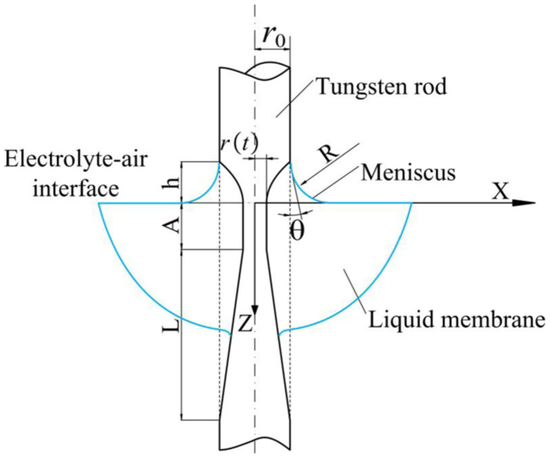
Mathematical model of dynamic liquid membrane electrochemical etching.
Part 1 is subjected to etching by the meniscus formed as a result of surface tension. The height of this meniscus is related to the initial diameter of the rod and the properties of the electrolyte as follows
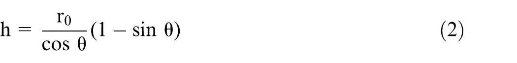
where
where
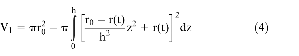
Part 2 is immersed in electrolyte within the amplitude of the reciprocating motion. Thus, it has the shape of a homogenous cylinder. The volume of material that is removed in its formation is given by

where
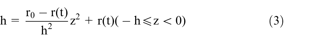
The shape of part 3 is approximately a reverse cone, caused by increasing diffusion layer thickness. 15 It can be described by the following expression
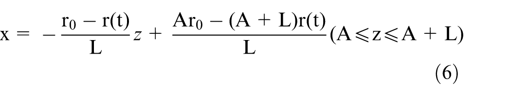
where
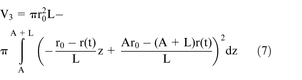
Thus, the total volume etched from the tungsten rod is the sum of

Substituting the expressions for
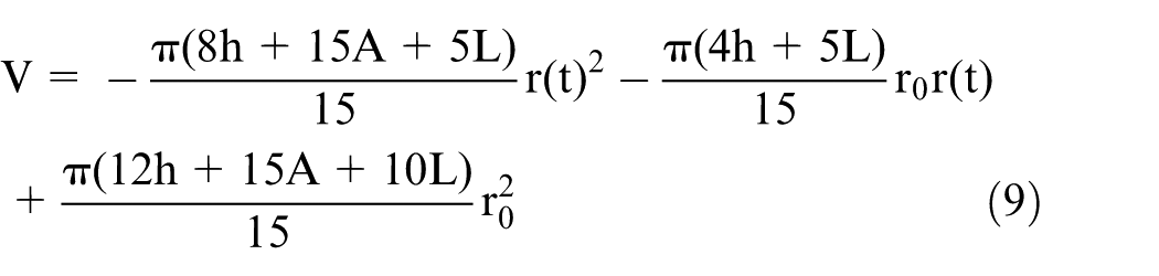
According to Faraday’s laws of electrolysis, the volume of the material removed can be expressed as follows
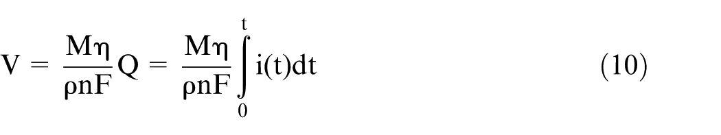
where
Finally, an indirect relationship between the final diameter and the etching time can be obtained by substituting equation (9) into equation (10)
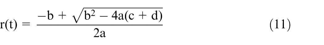
where
To obtain a direct relationship between the final diameter and the etching time, the relationship between the current and the etching time is needed. Thus, an experiment needs to be conducted to collect data on the variations in current.
Experimental setup
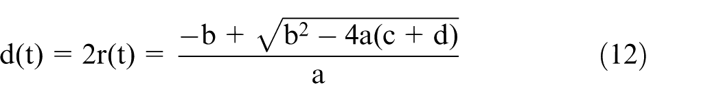
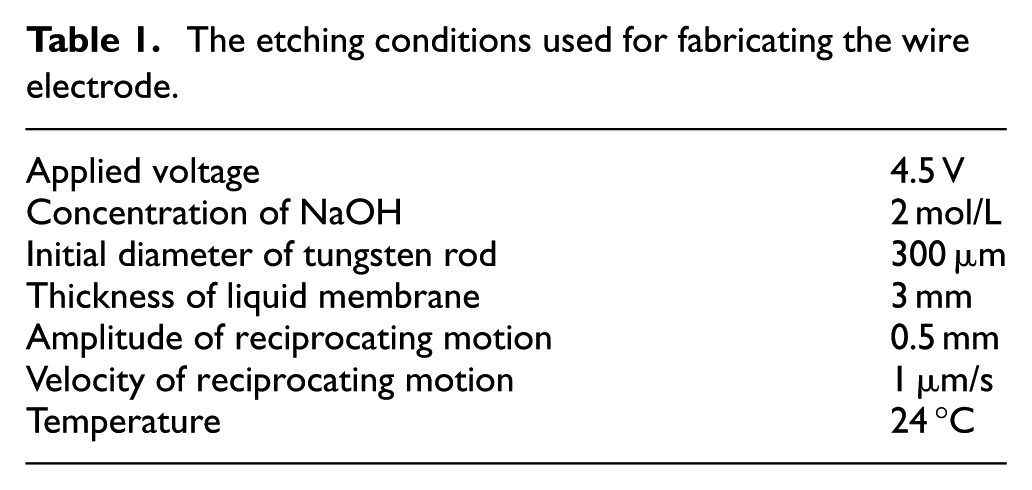
As shown in Figure 4, the wire ECM system developed for this study includes an operating platform, a motion control system, and a machining area. The motion control system consists of three precise X–Y–Z positioning stages (PI, Germany). The movable parts of the X, Y, and Z axes are driven by DC servo motors with a resolution of 0.1 μm. The stages are controlled by a PC, using LabWindows/CVI™ as the interface. A container is fixed on the operating platform and has two separated sections for fabricating wire electrode and for WEMM, respectively. The wire electrode is fabricated in situ in the liquid membrane and can be used immediately for WEMM in the machining area. A DC power supply (ITECH, USA) provides the power for the experiment. The cathode is a curled 0.2 mm diameter tungsten wire, and the diameter of the ring is 6 mm. Since the shape of the liquid membrane is approximately hemisphere, the thickness of the liquid membrane is equal to the radius of the tungsten ring. The etching process is monitored with a charge-coupled device (CCD) camera (NAVITA, USA). The etching conditions are given in Table 1.
Schematic diagram of the experimental setup.
The etching conditions used for fabricating the wire electrode
Results and discussion
To examine variations in current, the value of the current was recorded. A fourth-order polynomial fit was made based on the experimental results, as shown in Figure 5.
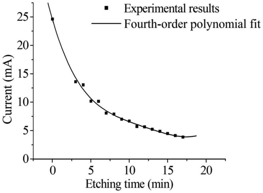
Experimental results and polynomial fit for the etching current.
The fourth-order polynomial fit for the current can be expressed as
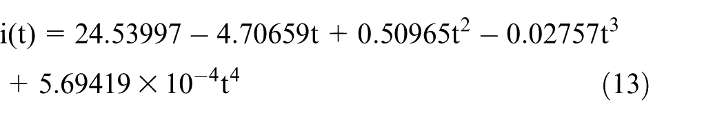
On substitution of this fit into equation (12), the relationship between the diameter of the wire electrode and the etching time can be obtained. A comparison between the experimental results and those of the simulation is shown in Figure 6.
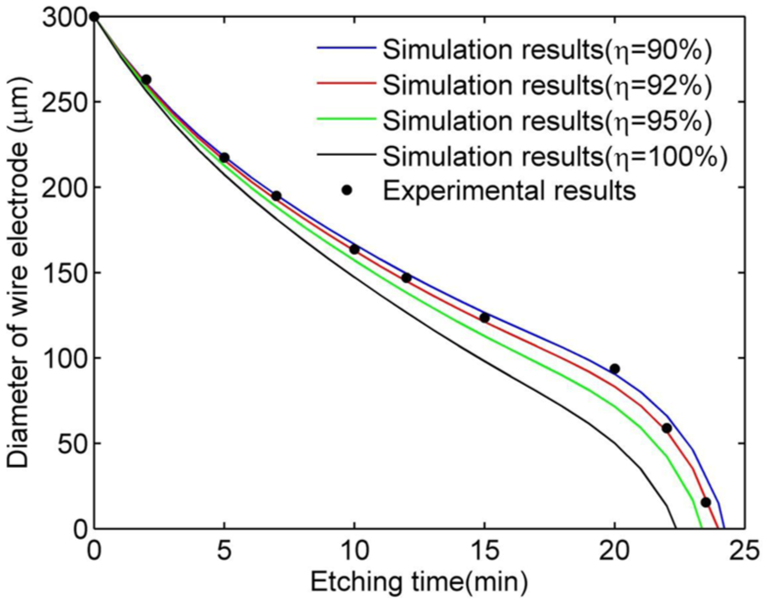
Variation in the diameter of the wire electrode with etching time.
At a current efficiency of 100%, the values from the simulation are smaller than the experimental values because no unwanted side reactions are considered. However, in reality, the current efficiency is less than 100% since Faradaic losses are experienced in all electrochemical reactions. Considering current efficiencies of 95%, 92%, and 90%, it is found that for an efficiency of 92%, the experimental results are in accord with the mathematical model, so this simulation curve is useful for estimating the diameter of the wire electrode.
In addition to estimating the electrode diameter from the simulation, a CCD camera, shown in Figure 4, was also utilized to visually monitor the variation in this diameter during the etching process, as shown in Figure 7.
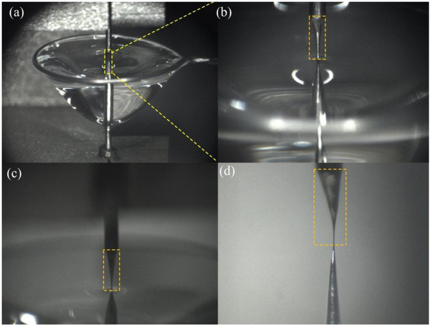
Variation in the diameter of the microwire electrode with time: (a) at the start of etching (t = 0), (b) etching time t = 21 min, (c) etching time t = 23 min, and (d) fabricated microwire electrode.
With the aid of the predictions of the mathematical model and the visual monitoring, a wire electrode with average diameter of 14 μm was successfully fabricated, as shown in Figure 8. It was a homogenous cylinder within a length of 200 μm.
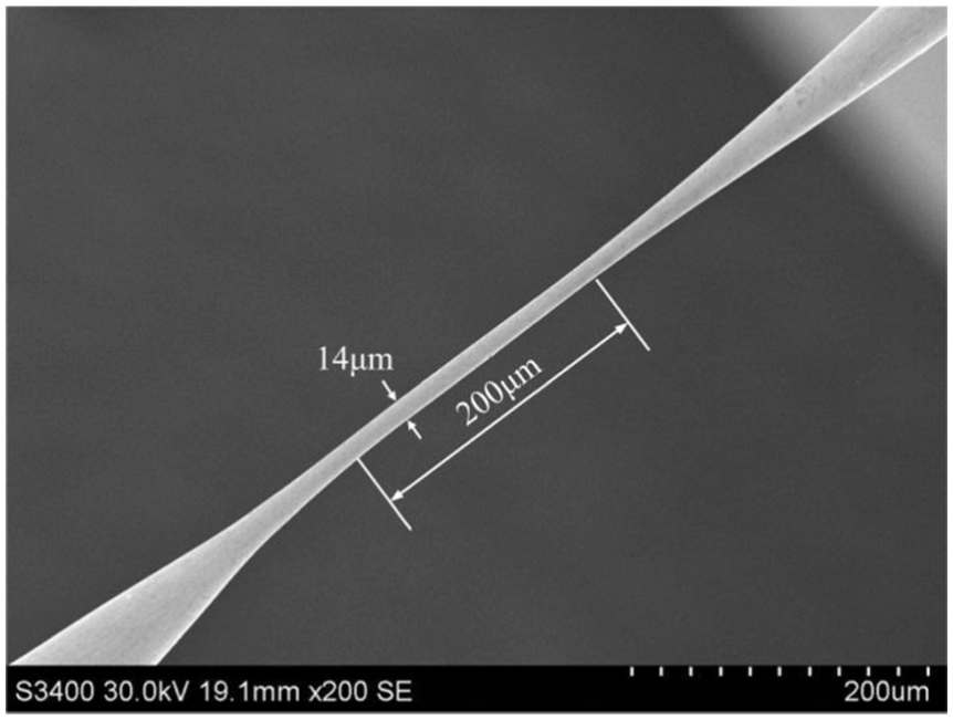
SEM image of fabricated wire electrode with an average diameter of 14 μm and a length of 200 μm.
By moving the precise X-Y-Z positioning stages (Figure 4), the prepared wire electrode was moved to the section of the container dedicated to WEMM, which was filled with 0.1 mol/L HCl solution. Whereas the wire electrode acted as the anode in dynamic liquid membrane electrochemical etching, it must be switched to become the cathode in WEMM so that the anodic workpiece can be electrochemically machined.
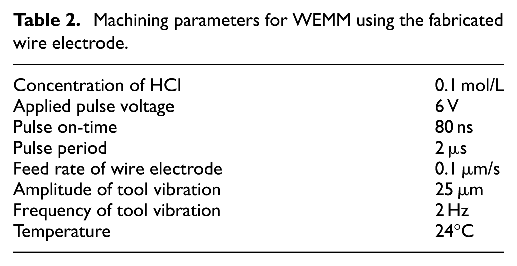
Figure 9(a) illustrates the principle of WEMM. The application of ultrashort voltage pulses between a tool electrode and a workpiece in an electrochemical environment allows machining of conducting materials with submicrometer precision. 18 In our experiment, a nanosecond pulsed voltage was applied between the wire electrode and the workpiece in an electrolytic cell. The applied voltage was 6 V with 80 ns pulse on-time and 2 μs pulse period. A nickel plate of thickness of 50 μm was used as the workpiece, as shown in Figure 9(b). As the wire electrode moved toward the anodic workpiece at the speed of 0.1 μm/s, material was removed electrochemically from the workpiece, with a narrow slit being created. To facilitate removal of electrolysis products and renewal of electrolyte, low-frequency (2 Hz) and small-amplitude vibrations (25 μm) were applied to the microtool in the direction parallel to the axis of the wire electrode. The machining parameters are given in Table 2. Finally, a microslit of width about 34 μm was successfully produced, as shown in Figure 10.
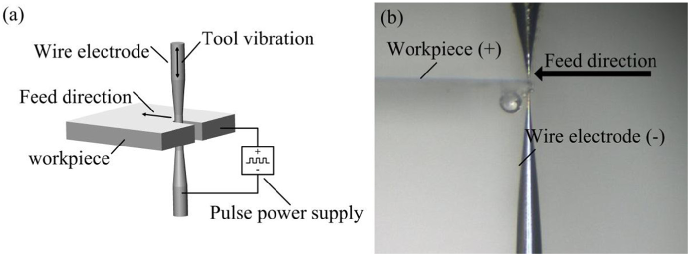
(a) Schematic diagram of the WEMM process and (b) photograph of WEMM using the fabricated wire electrode.
Machining parameters for WEMM using the fabricated wire electrode.
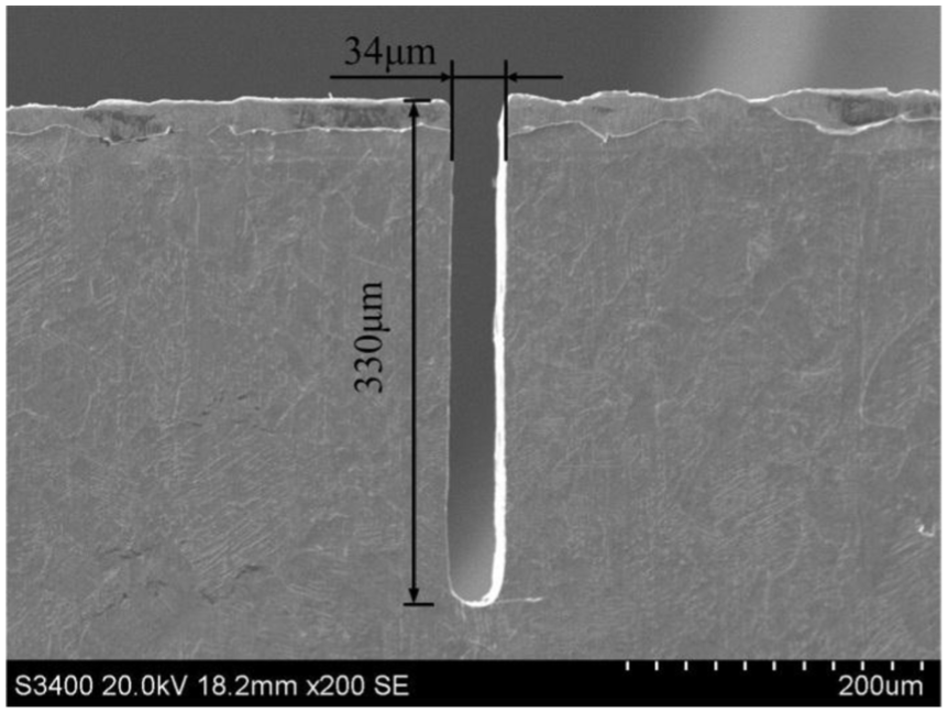
SEM image of microslit produced by WEMM using the microwire electrode fabricated in situ.
Conclusion
A method for in situ fabrication of a microwire electrode using liquid membrane electrochemical etching has been presented:
Fabrication of the electrode and subsequent WEMM can be performed in a single system, which is beneficial for improving the accuracy and efficiency of WEMM.
To improve the controllability of the size of the microwire electrode, a mathematical model of dynamic liquid membrane electrochemical etching has been constructed. Experimental results are in good agreement with results generated from the model.
Using the proposed method, microwire electrodes with the diameter of 14 μm have been produced, and microslits with the width of 34 μm have been electrochemically machined using the microwire electrode fabricated in situ.
Footnotes
Declaration of conflicting interests
The author(s) declared no potential conflicts of interest with respect to the research, authorship, and/or publication of this article.
Funding
The author(s) disclosed receipt of the following financial support for the research, authorship, and/or publication of this article: This work was supported by the National Natural Science Foundation of China (51675274).