
Abstract
In recent years, mechanical clinching has been widely used to join aluminium alloy sheets to build the automotive body. The high protrusion on the joint may limit the use of the mechanical clinching in the visible places. In order to get a lower protrusion, a compressing method was investigated in this work. Clinched joints with different geometrical parameters were used to conduct the experiments. AL5052 was taken as the material of the sheets. The protrusion of the clinched joint was compressed by two flat dies. A rivet placed in the pit of the clinched joint was used to control the metal flow in the compressing process. The top die moved downward to compress the protrusion, and the bottom die was fixed. The study shows that the tension-shearing strength and cross-tensile strength can be increased by the compressing method. The compressing method can increase the tension-shearing strength and cross-tensile strength by increasing the neck thickness. The compressed joint has larger neck thickness and lower protrusion than the clinched joint. Neck fracture mode is the main failure mode of the joints. The energy absorption can also be increased after the compressing process.
Introduction
In recent years, aluminium alloy has been widely applied to build the automotive structure and other areas.1–3 The joining of aluminium alloy sheets has been researched by many researchers.4–7 Spot welding is one of the effective methods to join sheets on the automotive structure. However, the aluminium alloy sheets are difficult to be joined together by spot welding because of the oxidation layer on the aluminium alloy sheet.8,9 In addition, spot welding is difficult to be used to join the coated metal sheets because of the coating. 10
Self-pierce riveting can be used to join aluminium alloy sheets. However, this joining method will penetrate the top sheet of the joint in the self-pierce riveting process, which may damage the sheets. The self-pierce riveting was widely used to join metal sheets because of a higher static strength. The self-pierce riveting technology using a solid rivet was investigated by Mucha 11 with numerical and experimental methods. In addition, a special clinch rivet was used to produce the mechanical joints.12–14 The special clinch rivet can increase the strength of the joint. This method was also proved to be efficient.15,16
Mechanical clinching is one effective joining method which uses plastic deformation to produce joint.17–20 The oxidation layer on the aluminium alloy sheet has little effect on the mechanical clinching process. 21 The top sheet is not penetrated by the mechanical clinching method. So, the mechanical clinching can be used to join aluminium alloy sheets instead of spot welding and self-pierce riveting in some areas.22–24 The mechanical clinching can also be used to join aluminium alloy sheet and high-strength sheet.25,26
Aluminium alloy sheets can be joined together with on flash, no light and no splash by the mechanical clinching method.27,28 Non-weldable, corrosion protection primer-coated and electro-galvanized metal sheets can also be joined together with no damage on the joint. 29 The coating condition of the metal sheets has little effect on the joining parameters and punch force. 30 As for the round clinching, the width of the die groove has an important influence on the material flow of the joint. 31 It is better to optimize the geometrical parameters of the clinching dies to get a higher strength.32,33
Aluminium alloy sheet can be joined together effectively by mechanical clinching. 34 However, a high protrusion was produced on one surface of the sheet in the clinching process. The application of the clinched joint may be limited by the exterior protrusion, which affects the appearance of the joined sheets. 35 In the visible areas, a lower protrusion is required. In order to get a lower protrusion, some reshaping methods were investigated in recent years.
Neugebauer and collegues36,37 investigated the dieless clinching, flat-clinching, self-pierce riveting, dieless-rivet clinching and mechanical clinching. All of these joining technologies can be used to join aluminium alloy sheets. The dieless clinching, flat-clinching, self-pierce riveting and dieless-rivet clinching have equivalent performance for economic efficiency compared with the mechanical clinching technology. In addition, the dieless clinching method can produce a lower protrusion, and the flat-clinching method can produce a flat plane with no protrusion.
In order to get a lower protrusion, a pair of reshaping tools was investigated and optimized by Wen et al. 38 The method was helpful to reduce the protrusion height. The top die and bottom die are contoured, which are difficult to produce. The clinched joint, top die and bottom die must be placed on the same axis, which made the operation complex.
In this work, a compressing process with a rivet to reduce the protrusion height was investigated. The compressing method consists of two phases. The first phase is mechanical clinching process, and the second phase is compressing process. Clinched joints with different geometrical parameters were used to conduct the experiments. The clinched joints were produced with AL5052 sheets by extensible dies. The material flow was controlled by a special rivet to enlarge the neck of the joint. Two flat dies were used to compress the protrusion of the joint in the compressing process. The tension-shearing strength, cross-tensile strength and energy absorption can be increased by the compressing method. The compressed joint has a larger neck thickness and a lower protrusion than the clinched joint. The compressing method was proved to be efficient.
Material and experimental procedure
In recent years, AL5052 sheet which is suitable to form the clinched joint has been widely used on the automotive body. AL5052 sheet with a thickness of 1.9 mm was used in this study. The mechanical properties of the AL5052 were measured by Instron 5982 machine. Poisson’s ratio of the AL5052 is 0.33, elastic modulus of AL6061 is 63.6 GPa and yield stress is 189.7 MPa. The AL5052 sheets were cut to be rectangular strips (80 mm × 25 mm).
The compressing method consists of two phases. The first phase is mechanical clinching process, and the second phase is compressing process. As shown in Figure 1, a conventional clinched joint was produced with a high protrusion and a pit in the mechanical clinching process. Metal plastic deformation was generated to form an interlock between the AL5052 sheets. The clinching process was performed with extensible dies on a mechanical clinching machine produced by express company. The speed and displacement of the clinching machine can be controlled precisely. The extensible dies consist of the spring, punch, fixed die, blank holder and sliding sectors. The punch was used to press the sheets to deform downward. The blank holder was used to fix the AL5052 sheets on the sliding sectors. The sliding sectors could slide away with the deformation of the AL5052 sheets.
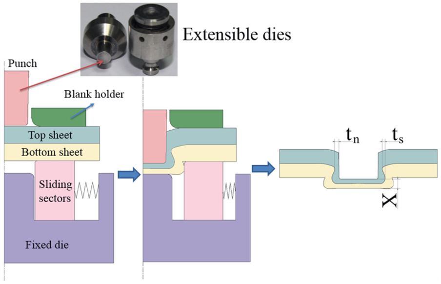
Clinching process.
The speed of the punch was set to 0.5 mm/s. The displacement of the punch was taken as the controllable parameter, so different bottom thicknesses could be produced by changing the displacement of the punch. The main geometrical parameters of the clinched joint are neck thickness, interlock and bottom thickness. The neck thickness and interlock are difficult to measure without cutting the joint along the centre shaft. The bottom thickness (X) is easy to measure without damage to the clinched joint. So, the bottom thickness is taken as the measurable and controllable parameter in the mechanical clinching process, which has been proved to be effective by many researchers.23,30 The neck thickness and interlock are difficult to measure without cutting the joint along the centre shaft. The bottom thickness (X) is easy to measure without damage to the clinched joint. 39 So the bottom thickness is always taken as the main measuring parameter to evaluate the quality of the clinched joint. The clinched joints were produced with bottom thicknesses of 1.4, 1.5 and 1.6 mm, respectively, by controlling the punch displacement.
The second phase is the compressing process. A rivet was used to control the metal flow in the compressing process. As shown in Figure 2, the protrusion of the clinched joint was compressed by two flat dies. A hydraulic servo press with a maximum load of 160 kN was used to conduct the compressing process. The force of the servo press can be controlled precisely. The controllable mode of the press was set to ‘force control’. The rivet was buried in the pit of the joint produced in the first phase. The joint with a rivet was placed between the two flat dies, and the protrusion was placed towards the top flat die. Many preliminary experiments have been carried out to investigate the compressing force. The compressed joint can get a higher static strength when the compressing force was set to 35 kN. So, the maximum force of 35 kN was chosen in this study. The top die moved downward with a speed of 0.05 mm/s in the compressing process, and the bottom die was fixed. When the force of the servo press increased to 35 kN, the top die stopped move at once.
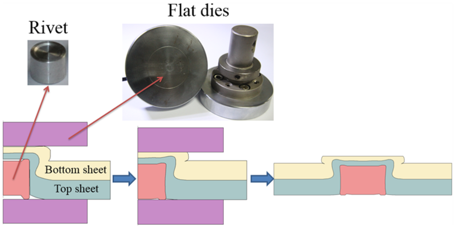
Compressing process.
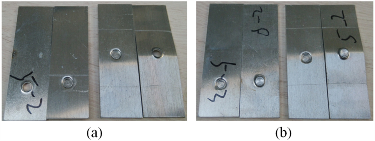
Tension-shearing strength and cross-tensile strength are two important parameters to evaluate the static strength of the clinched joint. Higher strength is required for the clinched joint used in the automotive body. Some researchers tended to take tension-shearing strength as the evaluation index of the strength of the clinched joint, and other researchers tended to take cross-tensile strength as the evaluation index.40–43 In this study, in order to investigate the mechanical properties of the height-reduced joints with different geometrical parameter roundly, both the tension-shearing test and cross-tensile test were carried out. The sample used for tension-shearing test is shown in Figure 3(a). The top and bottom sheets are cross shaped. The joint is located in the middle of the sheets. The sample used for cross-tensile test is shown in Figure 3(b). Tension-shearing test and cross-tensile test were conducted on Instron 5982 machine. Both the speeds of the tension-shearing test and cross-tensile test were set to 2 mm/min. When the joint was fractured, the strength test was stopped. The maximum force and force-displacement curve of the joint can be measured and recorded by Instron 5982 machine.
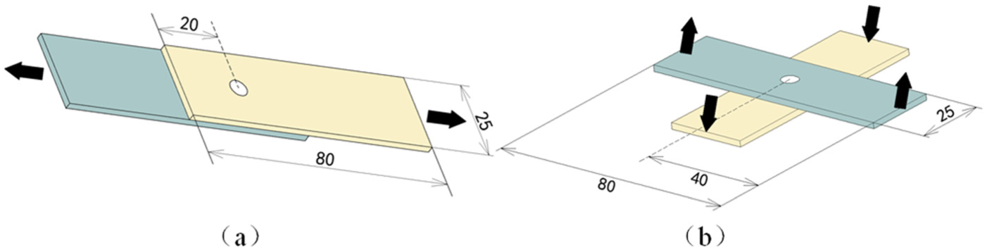
Sample used for strength test: (a) tension-shearing test and (b) cross-tensile test.
Results and discussion
The tension-shearing strengths of the clinched joints and compressed joints with different geometrical parameters are shown in Table 1. The bottom thickness was taken as the variable parameter. Five samples were tested for each tension-shearing test to get the average tension-shearing strength of the joint.
Tension-shearing strengths of the joints.
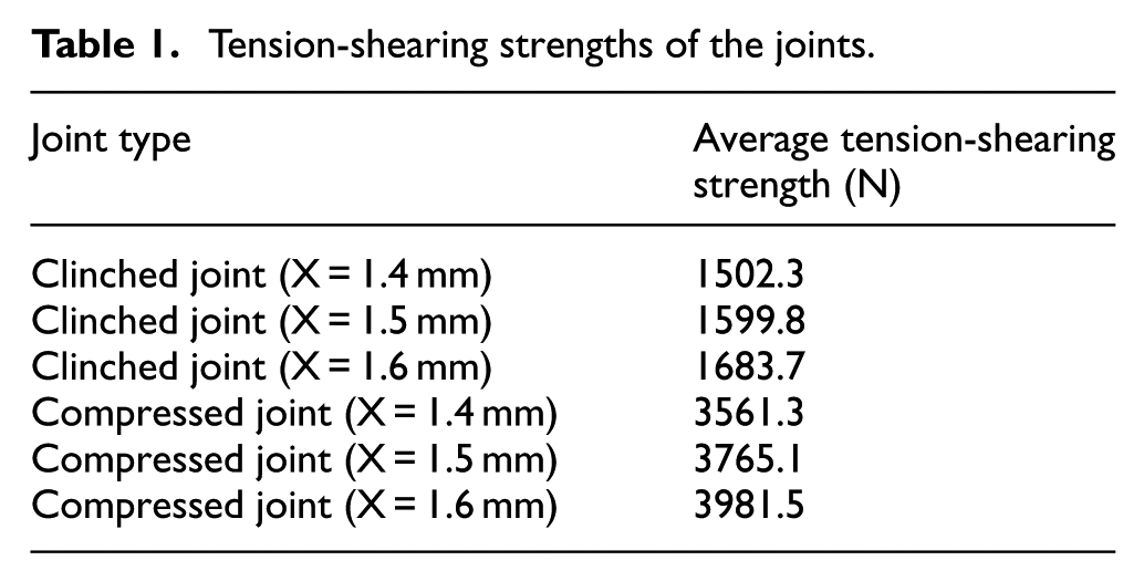
As can be seen, all of the clinched joints with different geometrical parameters have lower tension-shearing strengths than the compressed joints with different geometrical parameters. The tension-shearing strength of the joint can be increased by the compressing method.
The compressed joint with a bottom thickness of 1.6 mm has the highest tension-shearing strength among the compressed joints, and the clinched joint with a bottom thickness of 1.6 mm has the highest tension-shearing strength among the clinched joints. The strength of the compressed joint with a bottom thickness of 1.6 mm was increased by 136.5% compared with that of the clinched joint with a bottom thickness of 1.6 mm. The compressing method is effective for increasing the tension-shearing strength of the joint.
The compressed joint showed larger tension-shearing strength due to the placed rivet. The rivet placed in the pit of the joint can help the joint to bear the tension-shearing load in the tension-shearing test. With the help of the rivet, the joint can bear a higher tension-shearing load. In addition, the protrusion was compressed by the flat die in the compressing process. With the movement of the flat die, the material of the protrusion will flow to be gathered at the neck, which can enlarge the neck thickness. The strength of the compressed joint was also increased by increasing the neck thickness.
The tension-shearing force-displacement curves of different joints are shown in Figure 4. As can be seen, the tension-shearing forces were increased with the increase in the displacements before the force peak. After the force peak, the joints were fractured and the curves gradually dropped. The compressed joints with different geometrical parameters have larger displacements than the clinched joints. This proves that the compressed joint has a better performance for resistance to failure than the clinched joint.
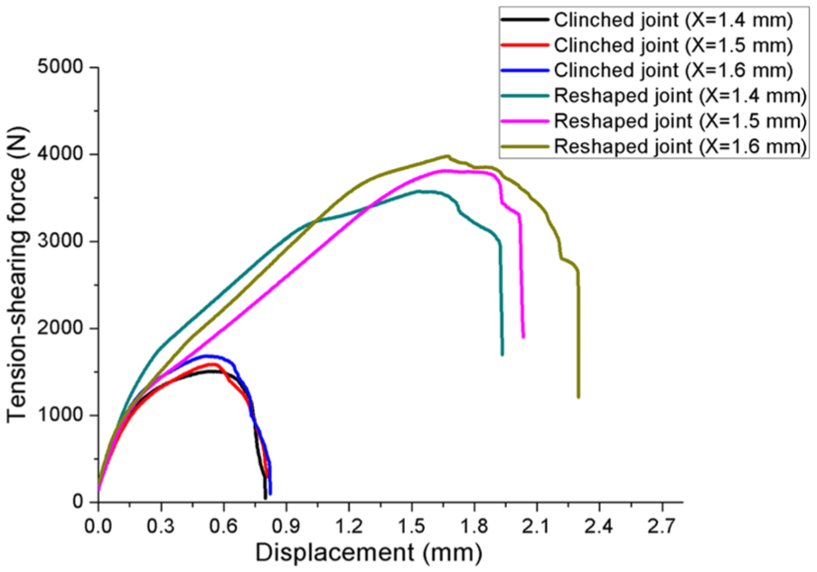
Tension-shearing force–displacement curves.
The cross-tensile strengths of the clinched joints and compressed joints with different geometrical parameters are shown in Table 2. Five samples were tested for each cross-tensile test to get the average cross-tensile strength of the joint.
Cross-tensile strengths of the joints.
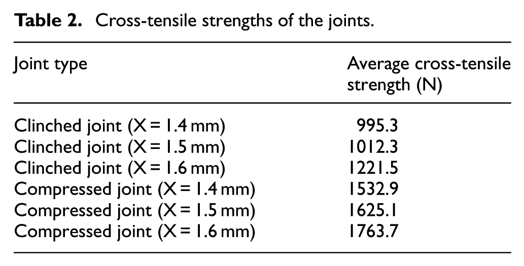
As can be seen, all of the clinched joints with different geometrical parameters have lower cross-tensile strengths than the compressed joints with different geometrical parameters. The cross-tensile strength of the joint can be increased by the compressing method.
The compressed joint with a bottom thickness of 1.6 mm has the highest cross-tensile strength among all the joints, and the clinched joint with a bottom thickness of 1.4 mm has the lowest cross-tensile strength. The cross-tensile strength of the compressed joint with a bottom thickness of 1.6 mm was increased by 44.4% compared with that of the clinched joint with a bottom thickness of 1.6 mm. The compressing method is effective for increasing the cross-tensile strength of the joint.
The cross-tensile force–displacement curves of different joints are shown in Figure 5. The cross-tensile force–displacement curves have similar growing trend. The curves dropped at once after the force peak, which is different with the tension-shearing force–displacement curves. The joints were fractured after the peak dropped.
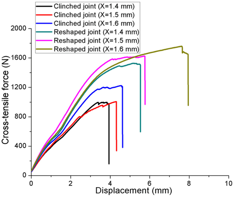
Cross-tensile force–displacement curves.
The failure mode of the joint is an important parameter to evaluate the quality of the joint. In general, there are two main fail modes for the clinched joints: neck fracture mode and button separation mode. Some joints with a thin neck may lose efficacy as a failure mode of neck fracture, and some joints with a small interlock may lose efficacy as a failure mode of button separation.
As shown in Figure 6, some joints with a thin neck may lose efficacy as a failure mode of neck fracture. There is an insufficient amount of material in the neck of the clinched joint and loading will result in the failure of the neck.
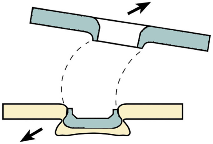
Neck fracture mode.
As shown in Figure 7, some joints with a small interlock may lose efficacy as a failure mode of button separation. A typically insufficient deformation produces a minor interlock of the sheet and loading will result in the button separation.
Button separation mode.
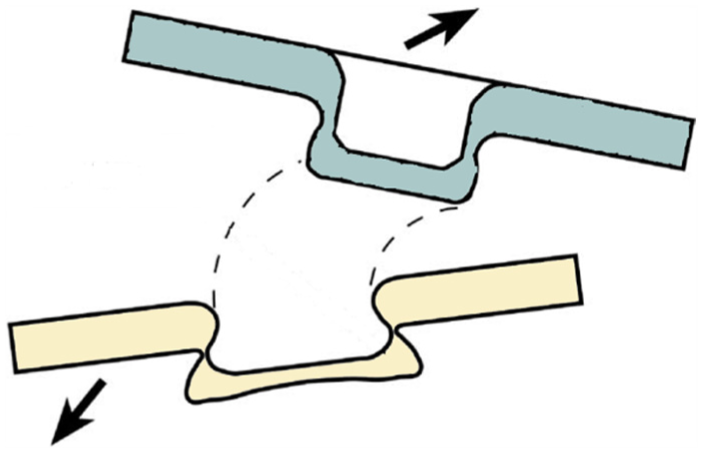
As shown in Figure 8, the main failure mode of the compressed joints in the tension-shearing test and cross-tensile test is neck fracture mode, and the failure mode of the clinched joints is also neck fracture mode. The fracture mode was not changed by the compressing method. The neck fracture mode is due to a thin neck, and the interlock of the joint can bear a larger force than the neck. When the force was increased to be larger than the load ability of the joint, a crack was generated on the neck of the joint. Then, the crack extended to result in the neck fracture. The top AL5052 sheet was separated with the bottom AL5052 sheet.
Failure mode of the joints: (a) clinched joints and (b) compressed joints.
As for the button separation mode, the strength of the joint was mainly determined by the interlock. As for the neck fracture mode, the strength of the joint was mainly determined by the neck thickness. Neck fracture mode is the main failure mode in this study. The joints were fractured due to a small neck thickness. The neck thickness is the determining factor for the strength of the joints.
In this study, the strength of the joint was mainly affected by the neck thickness. As shown in Figure 9, the joint was cut along the centre shaft. Then, inverted metallographic microscope was used to see the profile of the joint. The neck thickness (tn) and other geometrical parameters can be measured by the figure of the profile. The main geometrical parameters of different joints are shown in Table 3.
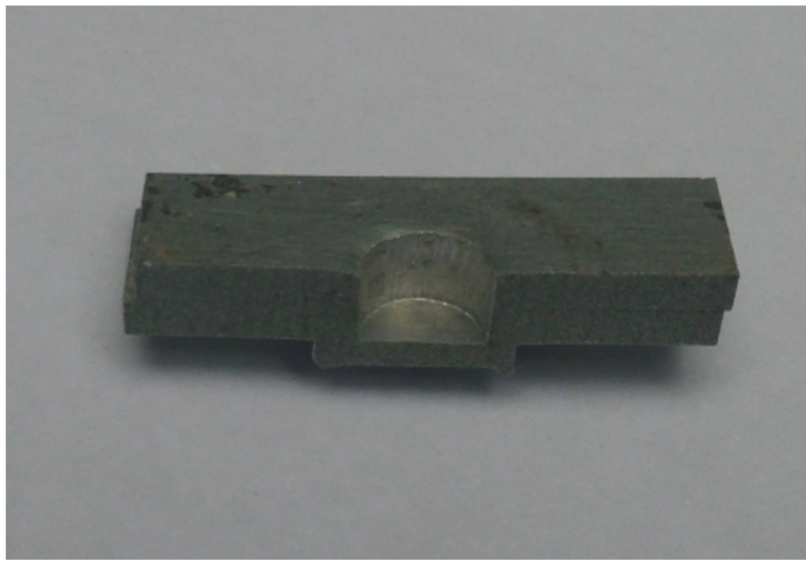
Cut joint.
Main geometrical parameters of different joints.
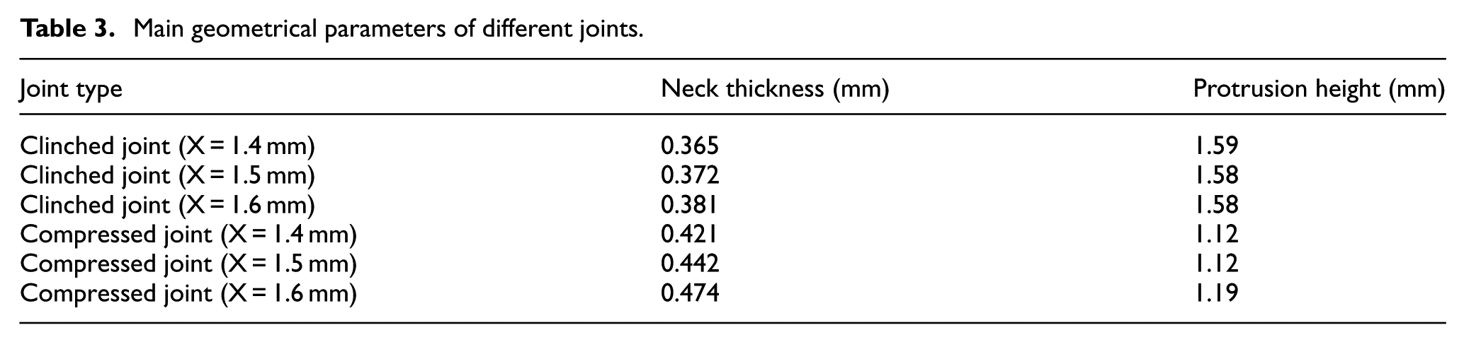
As can be seen from Table 3, the tension-shearing strength and cross-tension strength of the joints have similar trend with the neck thickness. The joint with a bottom thickness of 1.6 mm has the largest neck thickness, so it has the largest strength. The compressing method can increase the neck thickness by compressing the protrusion. In the compressing process, because of the rivet to support the neck, the material of the protrusion was pressed to flow downward to be gathered in the neck. So, the neck thickness was increased to increase the strength of the joint.
As can be seen from Table 3, the protrusion height was also reduced by the compressing method. The protrusion height of the compressed joint with a bottom thickness of 1.6 mm was reduced by 24.7% compared to that of the clinched joint with a bottom thickness of 1.6 mm. The protrusion height can be observably reduced by the compressing method.
The comparison of the appearances and cross-sectional shapes of the compressed joint with a bottom thickness of 1.4 mm and the clinched joint with a bottom thickness of 1.4 mm are shown in Figure 10. The left part of the figure is the compressed joint with a bottom thickness of 1.4 mm, and the right part of the figure is the clinched joint with a bottom thickness of 1.4 mm. As can be seen, the top sheet and bottom sheet are still hooked together by the interlock after the compressing process. The interlock was not damaged in the compressing process. The neck thickness was increased by compressing the protrusion, and the protrusion height was reduced.
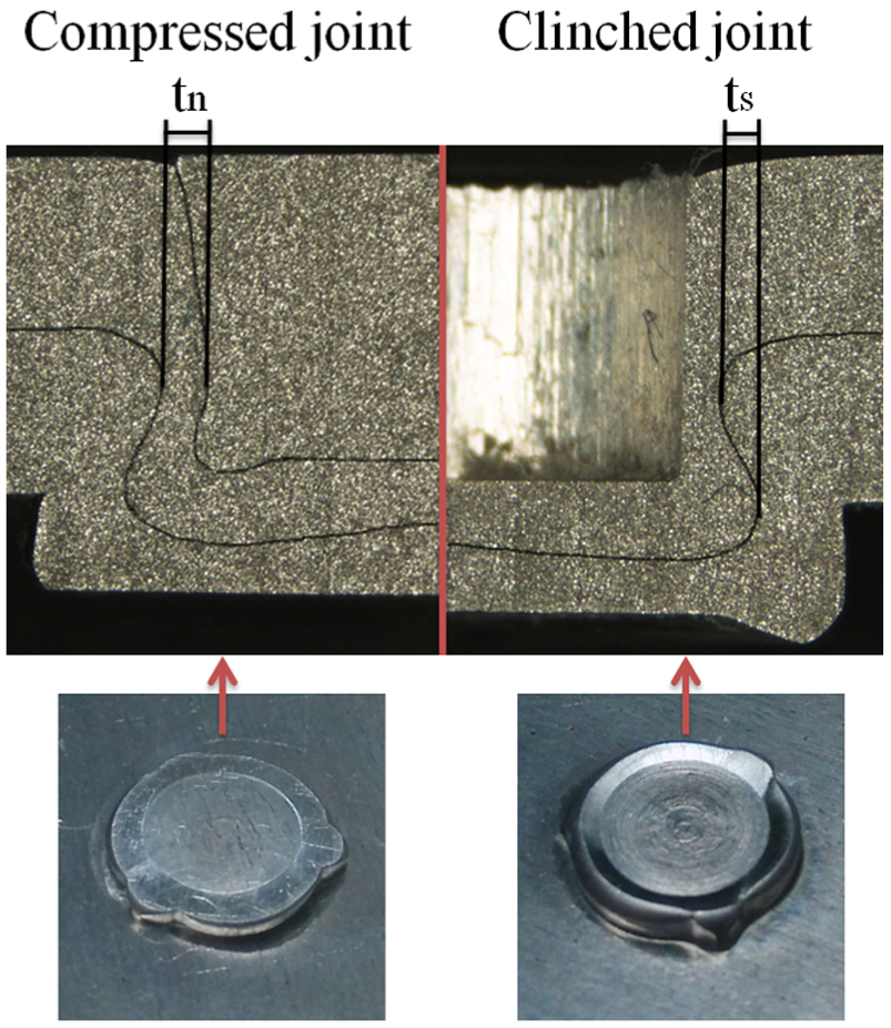
Appearances and cross-sectional shapes of the joints.
As for the joint used on the automotive body, a better performance for energy absorption is required. The energy absorption in the failure process is an important parameter to evaluate the quality of the joint. The energy absorption can be obtained by measuring the areas between the x axis and force–displacement curve. The energy absorption of different joints in the tension-shearing tests and cross-tensile tests is shown in Figure 11.
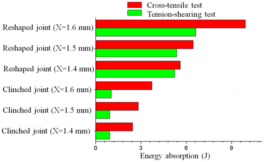
Energy absorption of different joints.
As can be seen, the compressed joint with a bottom thickness of 1.6 mm has the highest energy absorption among the compressed joints, and the clinched joint with a bottom thickness of 1.6 mm has the highest energy absorption strength among the clinched joints. The energy absorption of the compressed joint with a bottom thickness of 1.6 mm was increased by 537.6% compared with that of the clinched joint with a bottom thickness of 1.6 mm in the tension-shearing test, and the energy absorption was increased by 165.9% in the cross-tensile test. The compressing method can help the joint to absorb more energy in the strength test. With higher energy absorption, the safety of the joining of aluminium alloy sheet on the automobile can be improved.
The moulding process is composed of two processes: clinching process and compressing process. The destruction process is shown by the strength test. The clinching process is used to produce clinched joint. The compressing process is used to produce compressed joint after the clinching process. The energy consumption of the compressing process and clinching process is shown in Figure 12. As can be seen, the energy consumption in the compressing process is larger than that in the clinching process.
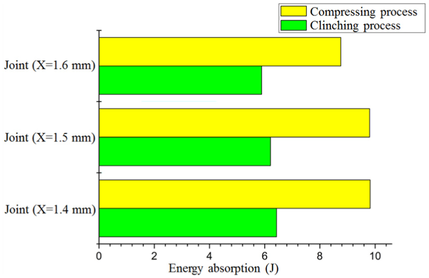
Energy consumption of the compressing process and clinching process.
The energy consumption of the joint with a bottom thickness of 1.6 mm in the compressing process was increased by 48.7% compared to that in the clinching process. The compressing process may consume more energy. However, the energy absorption of the compressed joint with a bottom thickness of 1.6 mm was increased by 537.6% compared with that of the clinched joint with a bottom thickness of 1.6 mm in the tension-shearing test, and the energy absorption was increased by 165.9% in the cross-tensile test. The compressing process can help the joint to absorb more energy in the strength test. Compressed with the energy consumption in the moulding process, the increase in the energy absorption in the strength test is more effective.
The increase in strengths and energy absorption of the compressed joint was caused by the rivet and the increased neck thickness. Neck fracture is the main failure mode of the joint in this study. As for the neck fracture mode, the strength of the joint was mainly determined by the neck thickness. So, neck thickness is a main geometrical parameter for the compressed joint. The compressing method can increase the strength of the joint by increasing the neck thickness. In addition, the rivet can also help the compressed joint to increase the strength. The rivet is kept in the pit of the clinched joint after the compressing process, which can also help the joint to bear the force. The rivet embedded in the pit of the clinched joint contributes to the increase in the static strength, and it also deforms to absorb more energy in the strength test. So, the compressed joint has a higher static strength than the clinched joint.
Conclusion
In order to get a lower protrusion, a compressing method using a rivet was investigated in this study. The compressing method consists of two phases. The first phase is the mechanical clinching process with extensible dies, and the second phase is the compressing process with a special rivet and a pair of flat dies. The main conclusions of this work can be drawn as follows:
The tension-shearing strength and cross-tensile strength of the joint can be increased by the compressing method. The compressed joint with a bottom thickness of 1.6 mm has the highest tension-shearing strength and cross-tensile strength.
Neck fracture mode is the main failure mode in this study. The neck of the joint has an important influence on the strength of the joint. The compressed joint with a bottom thickness of 1.6 mm has the largest neck thickness.
The protrusion height can be observably reduced by the compressing method. The protrusion height of the compressed joint with a bottom thickness of 1.6 mm was reduced by 24.7% compared to that of the clinched joint with a bottom thickness of 1.6 mm.
The compressing method can help the joint to absorb more energy in the strength test.
Footnotes
Declaration of conflicting interests
The author(s) declared no potential conflicts of interest with respect to the research, authorship and/or publication of this article.
Funding
The author(s) disclosed receipt of the following financial support for the research, authorship, and/or publication of this article: This research work was financially supported by the National Natural Science Foundation of China (Grant Nos. 51305333 and 51675414).