
Abstract
In order to reduce the protrusion height and increase the strength of the clinched joint, a two-step clinching method was investigated in the present study. The whole process contains two steps. The first step is used to produce one-step clinched joints, and the second step is used to press the one-step clinched joints to reduce the protrusion height and increase the joining strength. The influences of clinching steps and sheet thicknesses on the mechanical properties of the clinched joint were investigated. The main failure mode of all the clinched joints in the strength tests is the neck fracture mode. The neck thickness can be enlarged by the two-step clinching method, and the protrusion height can be reduced. TCJ2.5-2.0 joint has the highest energy absorption and strength, and OCJ2.0-2.5 joint has the lowest energy absorption and strength. The two-step clinching process can contribute to increasing energy absorption and joining strength. For getting higher strength, the thick sheet should be taken as the top sheet. With higher strength and lower protrusion, the use of two-step clinched joint will be convenient in the mechanical engineering areas.
Introduction
In order to realize emission reduction and energy conservation, the lightweight design of automotive bodies developed fast in recent years.1,2 One way to realize the light-weight design is to use light-weight materials.3,4 However, there are some problems in joining the light-weight materials to build the automotive body.
Traditionally, resistance spot welding is used to join sheets for several industry constructions.5,6 However, resistance spot welding is not suitable for aluminum alloy sheet. Sparks are produced in resistance spot welding process, which would contaminate environment badly.
Contrary to welding, clinching is one of the environmental joining methods for the light-weight metal sheet. 7 The undercut for joining sheets is formed by plastic deformation in clinching process. 8 No additional rivet or other parts is needed in this joining process. The oxide coating on sheet surface and high thermal conductivity of the aluminum alloy sheet, which limits the use of welding, have little effect on the formability of clinched sheets. Mechanical clinching allows the joining of dissimilar metal sheets, such as titanium alloy, aluminum alloy, copper alloy, and steel. 9
In recent years, more and more researchers gave attention to the clinching technology. Process parameters and clinching dies are investigated by many researchers. The material flow to produce the mechanical undercut was investigated numerically and experimentally by Lambiase.10,11 The joints with different processing parameters, such as forming forces, geometrical parameters of clinching dies, and sheet knee thickness were examined and analyzed. Taguchi method was used to conduct a parametrical study on the clinching process. 12 Response surface methodology was applied to optimize the shapes of clinching dies. 13 In order to join light-weight alloy sheets, Lee et al. 14 also proposed some new methods to design clinching tools and achieved good results.
The joining properties of the clinched joint are also investigated by many researchers.15–17 He et al.18–21 conducted some experiments and numerical simulations to get tensile strength and energy value in experimental tests. A clinch-bonded hybrid joining method was presented in their study to increase the joining strength, which gives rise to a good result in clinching experiments. The joining properties of polymer-metal clinched joints with different clinching dies were also investigated by Lambiase. 22 Round split dies are helpful to produce clinched joints with the best mechanical properties in the tensile and shearing tests. Theoretical analysis and finite element simulation were also used to investigate the mechanical properties of the clinched joint.23,24
It is difficult to join different materials using welding method. However, clinching process is suitable to be used for joining different metal materials. DP 780 steel sheet and AA5052 sheet were clinched together using plastic deformation. 25 The joining strength was determined by the undercut as well as the neck thickness. Abe et al. 26 also conducted some investigations to connect aluminum alloy and steel using clinching dies made by die block steel. The galvanized metal sheet is difficult to be joined effectively using traditional welding method. But galvanized steel and AA6111 aluminum can be joined using the clinching technology, which was proved to be feasible by Jiang et al. 27 Lambiase et al.28–31 paid more attentions to join the metal sheet with the polymer sheet using the clinching technology. In their studies, the clinched joint with metal sheet and polymer sheet can get better mechanical properties.
Compared with welded joint, the clinched joint has lower static strength. With a high joint protrusion, the application of clinching process is also limited. Therefore, some researchers tend to explore some new methods to improve the joining strength and reduce protrusion height. Mucha et al.32–37 investigated the joining method using a clinch-rivet to improve the joining strength. Chen et al.38,39 also used a rivet to reshape clinched joint for higher strength and lower protrusion. However, a special rivet is indispensable in their studies, which can increase the joint weight. For the light-weight automotive body, it is better not to increase the joint weight. Wen and other researchers40,41 used special contoured dies to reshape clinched joint. The protrusion height is reduced by this reshaping process. However, these special contoured dies are difficult to produce. In addition, these dies and clinched joint should be put on one axis, which makes operation complicated.
Metal sheets with different thicknesses are always used on mechanical engineering structures, such as automotive structures. The investigation of joining sheets with different thicknesses is significant. In order to get higher joining strength and lower protrusion, researchers should pay more attention to explore and investigate other new joining methods.
In this paper, an experimental research on the two-step clinching method was conducted to get higher joining strength and lower protrusion. The whole process contains two steps. The first step was conducted to get one-step joints, and the second step was conducted to press the one-step joints. The thicknesses of AA5052-H32 sheets were set to 2.5 and 2.0 mm in the joining experiment. The influences of clinching steps and sheet thicknesses on the joint mechanical properties were studied using experimental methods. The two-step clinching process can contribute to getting higher joining strength and lower protrusion. For getting higher strength, the thick sheet should be taken as the top sheet. With low protrusion and high joining strength, the two-step clinched joint will be adopted widely in many mechanical engineering areas.
Mechanism of the two-step clinching
As shown in Figure 1, the main purpose of the first step is to produce a fundamental clinched joint using extensible dies. The plastic deformation can be produced on the sheets by the punch. 42 With the plastic deformation, the material of the sheet will be pressed to flow downward to produce an undercut between two sheets. 43 These two sheets are joined together by the undercut with high strength. 44 After this process, one-step clinched joint is gotten.
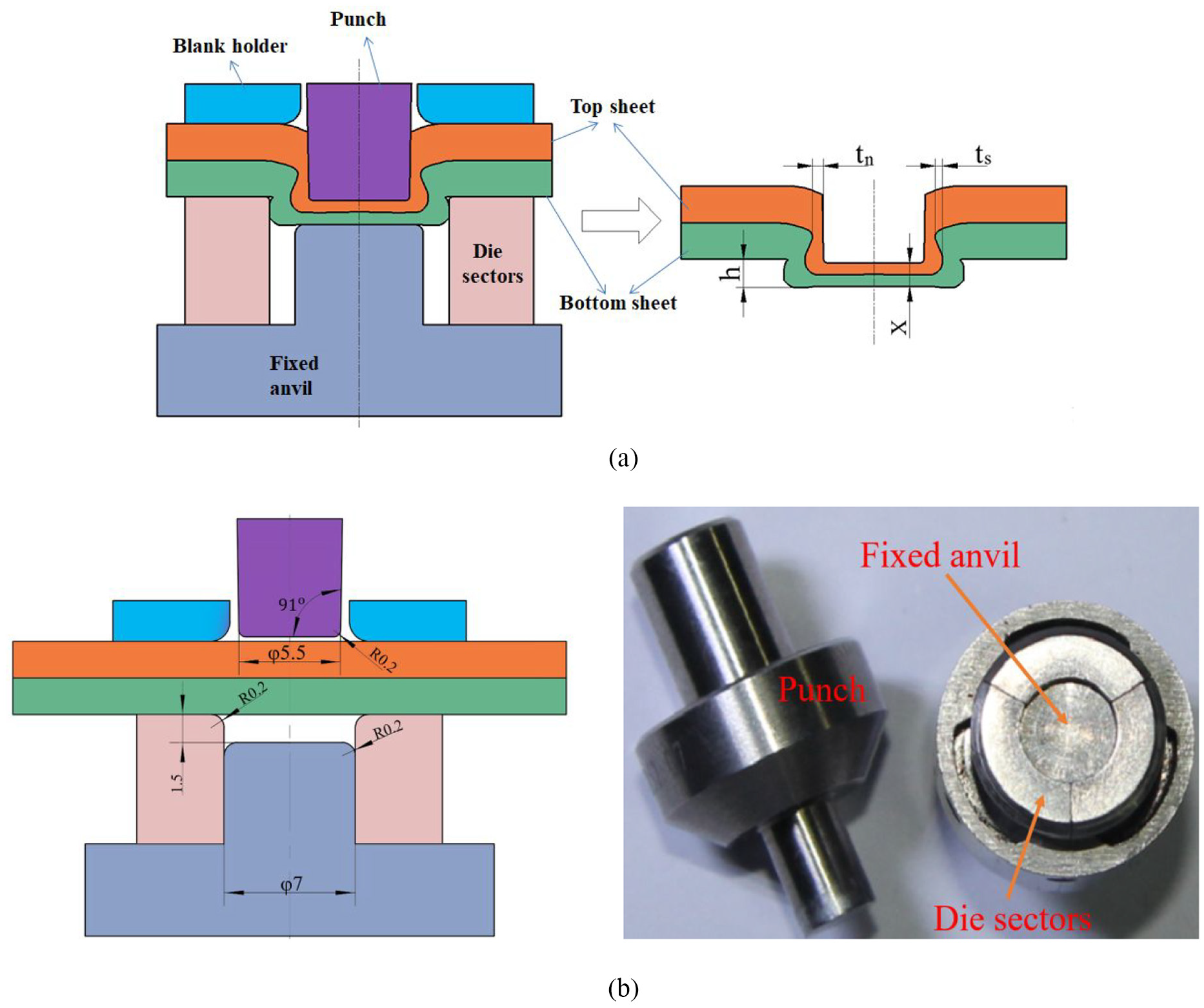
First step: (a) the schematic diagram of first step and (b) the sizes and photograph of the extensible dies.
Then the second step is carried out to form two-step clinched joint. Figure 2 shows that two similar flat dies are adopted to press one-step clinched joint. Firstly, one-step joint is put on a bottom flat die, and the sheet side with a hole faces down. Secondly, a top die moves downward to press high protrusion. The protrusion height will be reduced by the pressure. The undercut is not fractured in the second step, and two sheets are still hooked together. At last, two-step clinched joint is gotten with high strength.
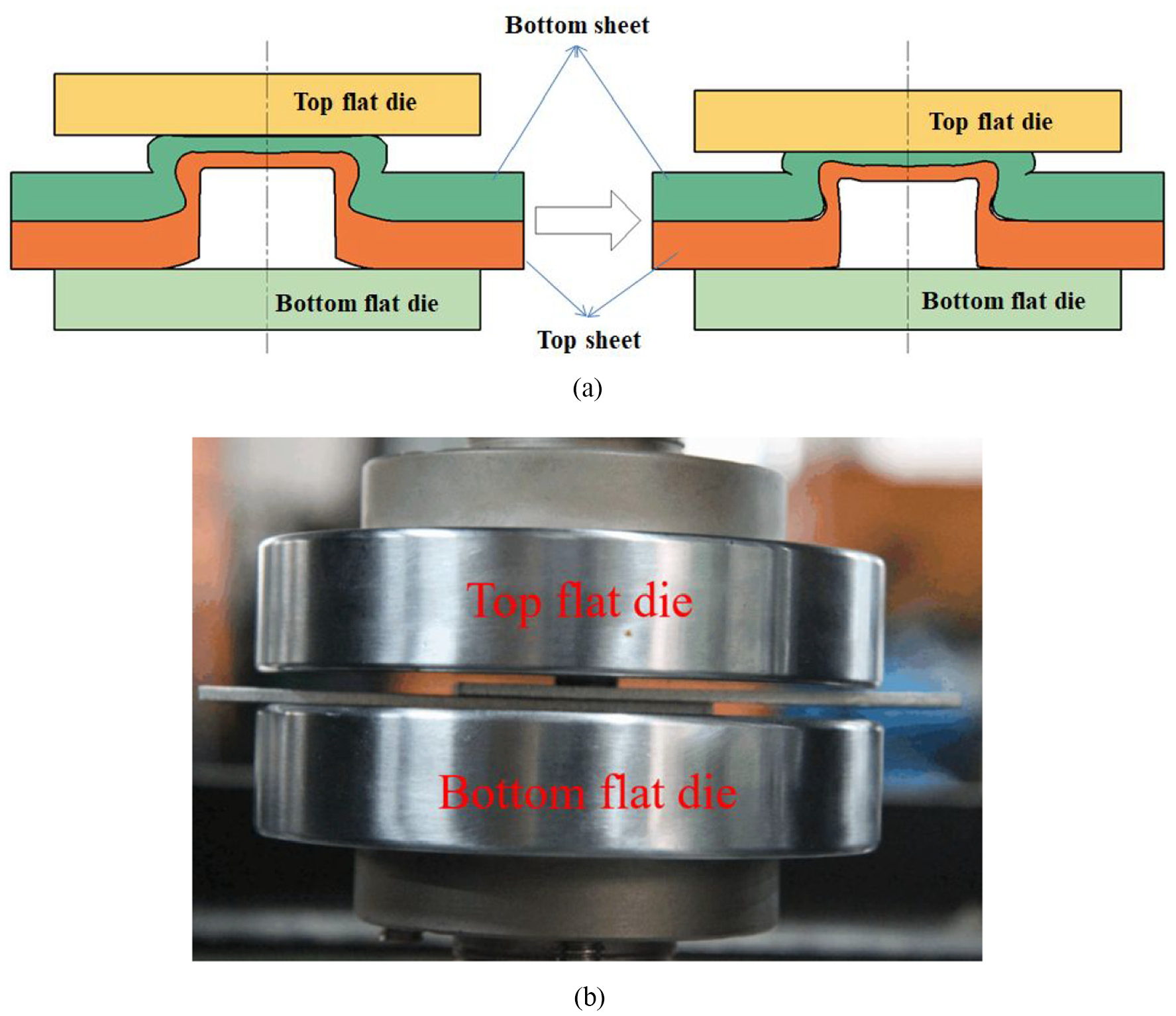
Second step: (a) the schematic diagram of second step and (b) the second step experiment.
Experimental procedure
One of the requirements for building automotive structures is to use the material with good formability, such as AA5052 aluminum alloy. In this study, AA5052-H32 sheets with 2.5 and 2.0 mm were used to conduct a series of joining experiments. The sheet was cut into the quadrangle shape with a length of 80 mm and a width of 25 mm along the rolling direction. The rolling direction was parallel to the length of the sheet. The elastic modulus, yield strength and Poisson’s ratio of AA5052-H32 were gotten on Instron 5982 test machine. Table 1 shows the AA5052-H32 mechanical properties. There were two kinds of sheet thickness. The thick sheet could be set as the top sheet, and the thin sheet also could be set as the top sheet. It is significant to investigate whether the thick sheet is suitable to be taken as the top sheet or not to get better mechanical properties.
Mechanical properties of AA5052-H32.
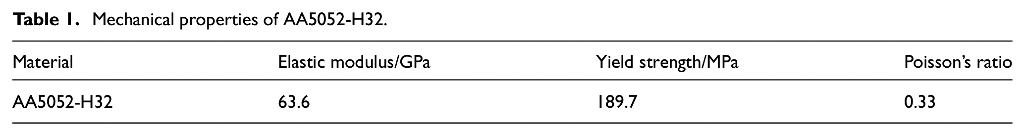
Figure 1(b) shows the sizes and photograph of the extensible dies with removable sectors, blank holder, fixed die, and punch. Three same removable sectors were adopted. Two sheets were fixed on sectors by the blank holder. The clinched joint could be produced between the punch and the fixed anvil. The punch moved down with a speed of 0.5 mm/s. One-step joint was gotten after the first experiment. In order to give clear joint descriptions with the sheet thicknesses of 2.0 and 2.5 mm, the descriptive approaches are adopted in the present study as follows:
OCJ2.5-2.0: one-step clinched joint using a lower sheet (2.0 mm) and an upper sheet (2.5 mm);
OCJ2.0-2.5: one-step clinched joint using a lower sheet (2.5 mm) and an upper sheet (2.0 mm).
After the first step experiment, one-step joint was pressed in the following experiment. Figure 2(b) shows two cylindroid dies which are adopted to press one-step joint. Top flat die moved down to press one-step clinched joint. The speed of the top die was 0.05 mm/s. The downward movement of the top die stopped when the compressing load reached 25 kN. In order to give clear joint descriptions with sheet thicknesses of 2.0 and 2.5 mm, the descriptive approaches are adopted in the present study as follows:
TCJ2.5-2.0: two-step clinched joint using a lower sheet (2.0 mm) and an upper sheet (2.5 mm);
TCJ2.0-2.5: two-step clinched joint using a lower sheet (2.5 mm) and an upper sheet (2.0 mm)
Higher strength means higher safety and reliability. There are two main joining evaluation criteria in cross-tensile strength and tension-shearing strength. Figure 3(a) shows the specimen used in cross-tensile tests. Two sheets are placed as crisscross shape. Figure 3(b) shows the joint specimen used in tension-shearing tests. Two sheets are placed as straight shape. These strength testing experiments were carried out on Instron 5982 test machine. Average strength was gotten by conducting five groups of strength tests for each joining type.
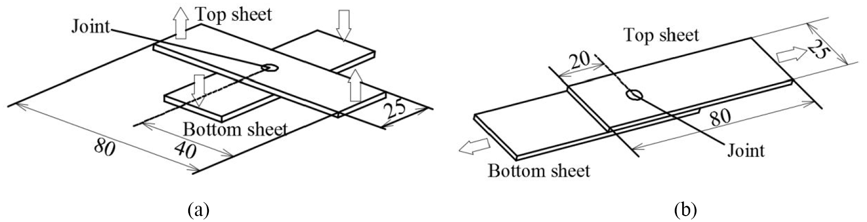
Specimens used for strength test: (a) cross-tensile strength test and (b) tension-shearing strength test.
Results and discussion
The failure of clinched joints may generate industrial accidents in the field of mechanical engineering, so it is significant to investigate the failure behavior of the clinched joint. If the load on the joint is too large, the clinched joint may fail as neck fracture or button separation in the testing experiments. If the neck strength is lower than the undercut strength, the joint could be destroyed as neck fracture. If neck strength is higher than the undercut strength, the joint may be destroyed as button separation.
The clinched joints were pulled to be fractured to get the maximum force in strength test. As shown in Figure 4, all of one-step joints and two-step joints were destroyed as neck fracture. The joint neck was destroyed after strength test. During the tensile test, the joint neck mainly bore the tensile load. Higher load resulted in damage that developed from the interfacial sheet surface. Subsequent the propagation of the crack gave rise to neck fracture. When the tensile stress was increased to exceed the fracture stress, the joint would be fractured at the neck area.
Neck fracture mode: (a) picture of failed joint and (b) the schematic diagram of failed joint.
The joining mechanical properties mainly depend on the geometrical parameters. Neck fracture mode occurred on all of the joints in these experiments, which means that the joining strength depends on the neck thickness. Figure 5 shows the neck thicknesses of one-step joints and two-step joints. According to the results, the joint with the largest neck thickness is TCJ2.5-2.0, and the joint with the smallest neck thickness is OCJ2.0-2.5.
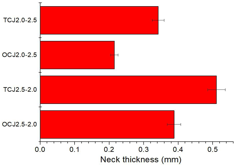
Neck thicknesses of the clinched joints.
The clinched joint using top thick sheet and bottom thin sheet has larger neck than the joint using top thin sheet and bottom thick sheet. The neck of clinched joint was generated by top sheet. The initial top sheet thickness determines the final neck thickness, which means that top thick sheet could generate thick neck.
One-step joint has a smaller neck thickness than two-step joint. In the second step, the joint protrusion was pressed. The protrusion material moved down to the neck area during the second step. With more and more materials flowing to the neck area, the neck would be enlarged. The two-step clinching technology can contribute to getting larger joint neck thickness.
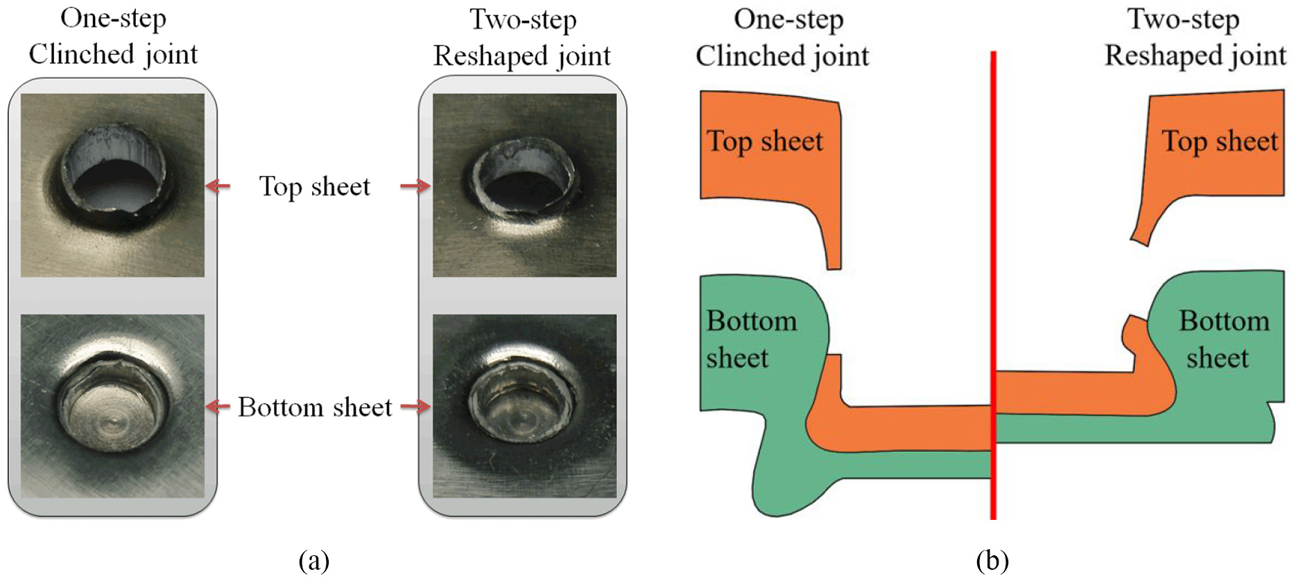
Figure 6 shows the cross-sectional shapes of one-step joints and two-step joints. The two different joint types are shown in one same figure, which can help to compare one-step joint with two-step joint easily. The one-step joint is on the left half side in these figures, and the two-step joint is on the right half side. The protrusion of two-step joint was lower than one-step joint. The two-step clinching process contributed to reducing protrusion height.
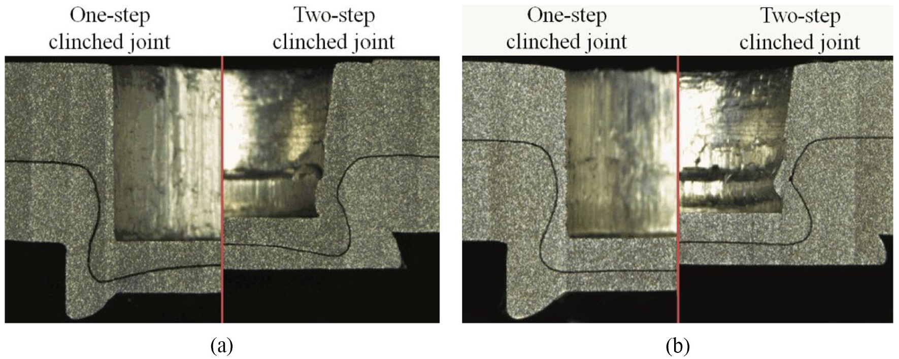
Cross-sectional shapes of the clinched joints: (a) OCJ2.5-2.0 joint and TCJ2.5-2.0 joint and (b) OCJ2.0-2.5 joint and TCJ2.0-2.5 joint.
Figure 7 shows the cross-tensile joining strengths of these joints. The joint with the highest strength is TCJ2.5-2.0, and the joint with the lowest strength is OCJ2.0-2.5. Compared with the top thin sheet, the top thick sheet could contribute to getting higher cross-tensile strength. In the failing process, the load was mainly born by the neck which is the main factor determining the strength. Top thick sheet can help to get a thicker neck, which also helps to get higher strength. The two-step joint also can get a higher strength than one-step joint. In the second step, the protrusion material flowed downward to the neck area, which could enlarge the neck thickness. Because of the larger neck, two-step joint could get higher strength in cross-tensile test.
Cross-tensile strengths of the clinched joints.
Figure 8 shows the load-displacement curves of these joints in cross-tensile test. The joint with the longest displacement is TCJ2.5-2.0. The displacement in failing process also can be enlarged by this two-step clinching technology, which is helpful to improve the structure safety. After the load peak, the load-displacement curves suddenly drop because of the neck fracture.
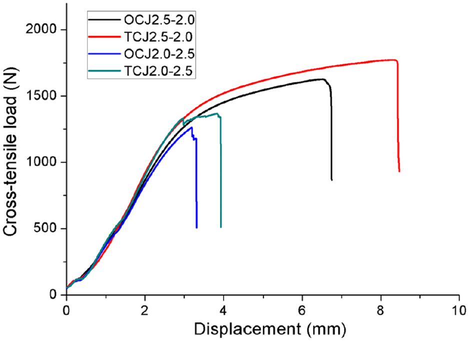
Cross-tensile load-displacement curves of the different clinched joints.
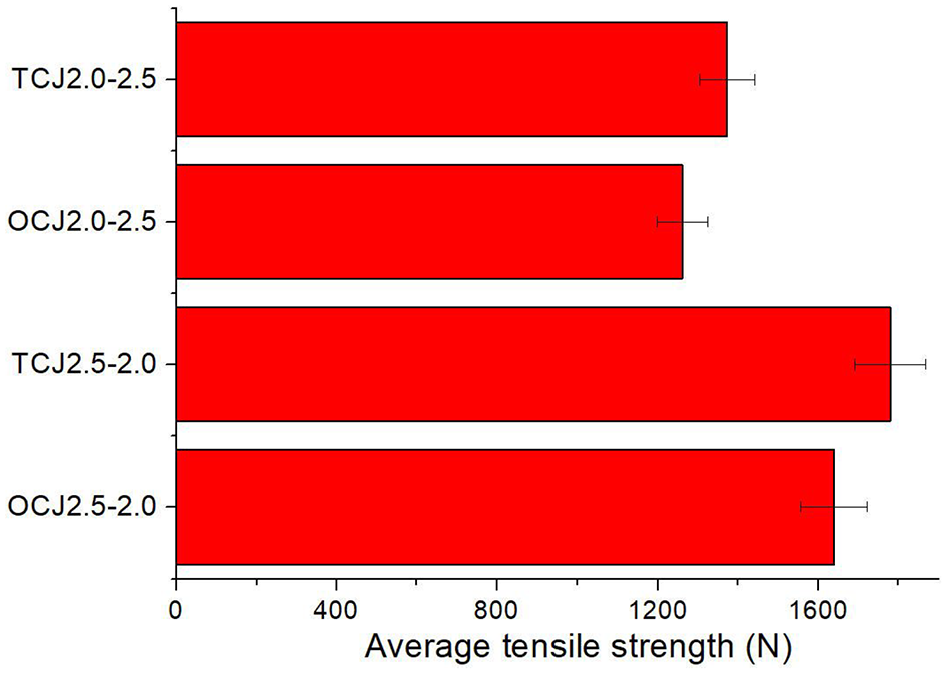
Tension-shearing strength tests were conducted to get tension-shearing strength. Figure 9 shows the tension-shearing strengths. The joint with the highest strength is TCJ2.5-2.0, and the joint with the lowest strength is OCJ2.0-2.5. Compared with the top thin sheet, the top thick sheet can get higher tension-shearing strength. The top thick sheet contributes to generating a larger neck which results in higher strength. Compared with one-step joint, the two-step joint also can get higher tension-shearing strength. In the second step, the protrusion material flowed downward to the neck area, which could enlarge the neck thickness. Because of larger neck thickness, the tension-shearing strength can be increased.
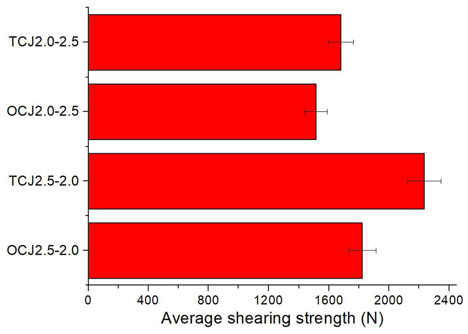
Tension-shearing strengths of the clinched joints.
Figure 10 shows the load-displacement curves of these joints in the tension-shearing test. All the joints undergo longer displacements in strength test. Compared with the top thin sheet, the top thick sheet contributed to getting a longer displacement. The displacement during failure process also can be increased by this two-step clinching technology.
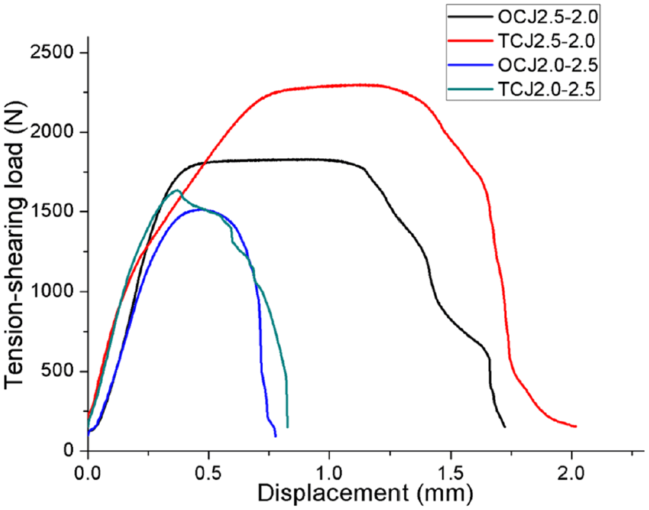
Tension-shearing load-displacement curves of the different clinched joints.
When a car is hit, the more energy clinched joints installed on the car absorb before failure, the safer the driver. As for the clinched joint, this factor is always taken as an important evaluation criterion. Higher energy absorption should be gotten to ensure the joining safety. This factor was gotten by calculating areas between load-displacement curves and abscissas.
Figure 11 shows the energy absorption in the cross-tensile strength test. The joint with the lowest energy absorption is OCJ2.0-2.5, and the joint with the highest energy absorption is TCJ2.5-2.0. Top thick sheet can help clinched joint get higher energy absorption. Compared with one-step joint, two-step clinching technology is helpful to make joint get higher energy absorption.
Energy absorption in cross-tensile strength test.
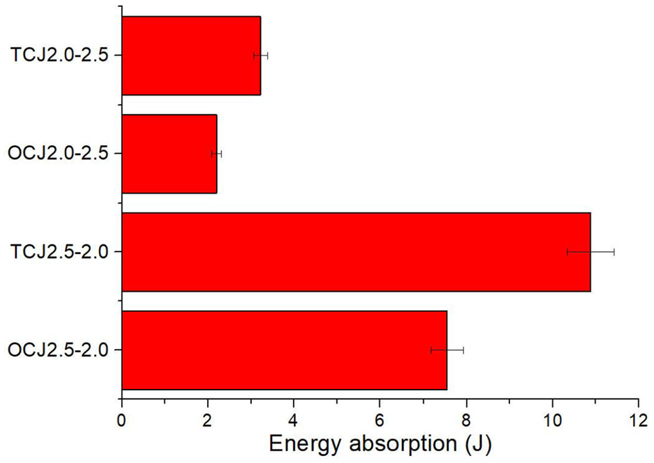
Figure 12 shows the energy absorption in the tension-shearing strength test. The joint with the lowest energy absorption is OCJ2.0-2.5, and the joint with the highest energy absorption is TCJ2.5-2.0. The top thick sheet results in higher energy absorption. Compared with one-step joint, two-step clinching technology is helpful to make joint get higher energy absorption.
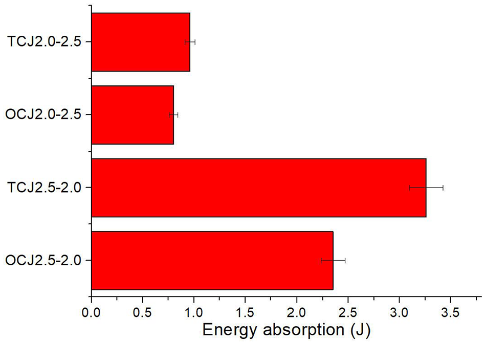
Energy absorption in tension-shearing strength test.
In addition to two-step clinching method using two flat dies without a rivet in this paper, there are two other two-step clinching methods depicted in Figure 13 (two-step clinching method using a flat die and a bumped die, 41 as well as two-step clinching method using two flat dies with a rivet. 38 ). They can also reduce the protrusion height and enhance the static strength of the clinched joint. Compared with the clinched joint using the other two-step clinching methods, the clinched joint utilized two-step clinching method using two flat dies without the rivet has lower static strength. However, two-step clinching method using two flat dies without the rivet has some other advantages. Compared with two-step clinching method using the flat die and the bumped die, its dies (two flat dies) are easier to manufacture and have a longer service life. Its clinched joint has a lower weight and a lower cost than two-step clinching method using two flat dies with the rivet. Therefore, it has application potential in the lightweight metal joining field.
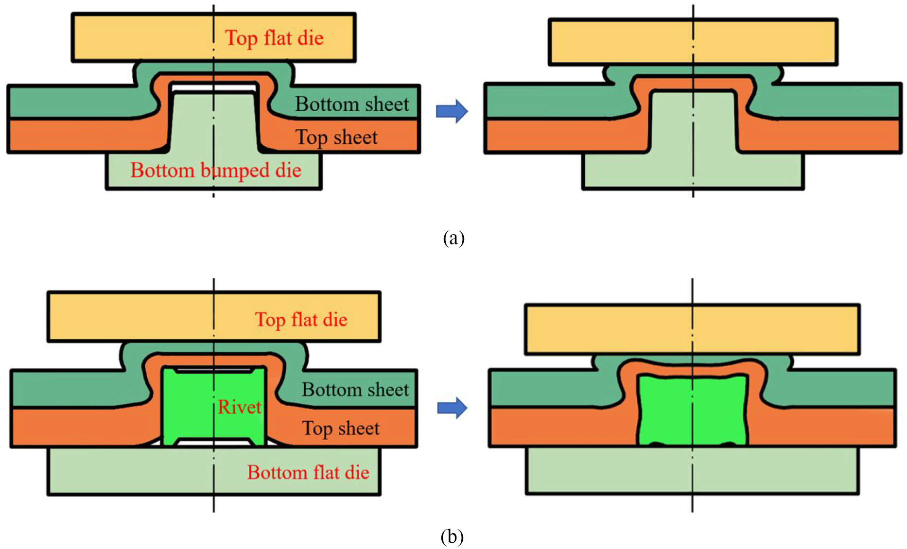
Two other two-step clinching method: (a) two-step clinching method using a flat die and a bumped die and (b) two-step clinching method using two flat dies with a rivet.
Conclusion
A two-step clinching technology was investigated to increase strength and reduce protrusion height in this paper. There were two steps in the whole joining process. The first step was carried out to produce one-step joint, and the second step was used to press one-step joint for increasing the joining strength. The influences of clinching steps and sheet thicknesses on the joint mechanical properties were studied in this paper.
All of different joints failed as neck fracture, which proves that the joining strength depends on neck thickness in this study. The two-step clinching technology is helpful to enlarge neck area, and taking thick sheet as top sheet also can enlarge the neck area. The joint with the lowest joining strength is OCJ2.0-2.5, and the joint with the highest joining strength is TCJ2.5-2.0. Compared with the top thin sheet, the top thick sheet gave rise to higher strength. By enlarging the neck area, the strength was also increased by the two-step clinching method. The joint with the lowest energy absorption is OCJ2.0-2.5, and the joint with the highest energy absorption is TCJ2.5-2.0. Compared with top thin sheet, the top thick sheet gave rise to higher energy absorption. The joint energy absorption was increased using this two-step method.
Footnotes
Declaration of conflicting interests
The author(s) declared no potential conflicts of interest with respect to the research, authorship, and/or publication of this article.
Funding
The author(s) disclosed receipt of the following financial support for the research, authorship, and/or publication of this article: This research work is supported by the National Natural Science Foundation of China (Grant No. 51805416), Young Elite Scientists Sponsorship Program by CAST, Natural Science Foundation of Hunan Province (Grant No. 2020JJ5716), Natural Science Basic Research Plan in Shanxi Province of China (Grant No. 2019JQ-372), the Project of State Key Laboratory of High Performance Complex Manufacturing, Central South University (Grant No. ZZYJKT2019-01), and Huxiang High-Level Talent Gathering Project of HUNAN Province (Grant No. 2019RS1002).