
Abstract
Clinching technology has been extensively applied as a green and clean joining method, which has the benefits of less energy consumption, no pollution and no noise. However, a single joint produced by round tools cannot withstand the torsion force. In order to solve this problem, a square clinching technology was proposed and investigated in this paper. The main geometric parameters, failure mode, static strength, and energy absorption of the square clinched joint were studied. The fracture characteristics of square clinched joints under different mechanical experiments were studied by a scanning electron microscope. The strength tests of Al5052 clinched joints under various forming forces were carried out. The results showed that the neck fracture mode was the only failure mode observed during the failure process. The microscopic morphology of the joint fracture shows typical ductile fracture characteristics. It turned out that the square clinching process can effectively join aluminum alloy sheets.
Introduction
In recent years, the public has paid generous attention to the environmental performance of industrial products. 1 In the context of energy shortage, it is urgent to drop energy consumption. 2 The vehicle manufacturing industry has been eager to use a variety of materials and make full use of the special properties of these materials to improve vehicle performance, reduce costs, and reduce energy consumption. The weight of thin-walled structure can be effectively reduced by using lightweight materials. Aluminum alloy, magnesium alloy and other lightweight materials have been widely utilized to build the thin-walled structures on aircraft and automobiles.3–5 However, the joining of aluminum alloy is tough to be realized by the conventional spot welding method due to the existence of the oxide layer. 6 In addition, flash and smoke will emerge in large quantities during welding, which are contrary to environmental friendly concept and threatens the health of workers.
A plenty of joining methods, such as self-piercing riveting, 7 adhesive bonds, mechanical clinching, 8 are suitable for green and clean joining of lightweight materials. The joints formed by self-piercing riveting technology will have greater static strength due to the use of rivets. However, the presence of rivets will also increase the weight and the cost of the joints. 9 Adhesive bonding is a technique that uses suitable adhesives to bond two parts together. 10 The joints produced by adhesive bonding technology have superior sealing property, and there will be no gaps and corrosion between the sheets. 11 Nevertheless, the surface used for joining needs to be sufficiently clean in order to ensure the bonding quality. Furthermore, the adhesive also demands sufficient time to solidify.
Mechanical clinching is also effective for the joining of lightweight materials. With the advantages of pollution-free, energy-saving, and low-cost, mechanical clinching is a superior joining technology. In addition, there is no need for any additional materials in the clinching process, effectively reducing the costs. The material undergoes huge plastic deformation, forming an interlock to realize the connection of the sheets.12,13 Many scholars have conducted research on energy absorption, fatigue strength, geometric parameters and static strength of the joint.14–17 Certain materials such as aluminum alloys, titanium alloys, magnesium alloys, ultra-high-strength steel, carbon-fiber composites polymers, and glass fiber reinforced polymers are unsuitable for welding. In this case, mechanical clinching is often the preferred joining technique for materials that are difficult to weld.18–25 The hybrid clinching that combines a variety of joining methods, such as bond-clinching, ultrasound-assisted clinching, laser-assisted clinching, rivet-clinching, has been extensively researched, expanding the application field of mechanical clinching.26–30 However, most of the existing clinching processes employed round punches. And the round joint cannot withstand the torsion force like the rectangular or the square joint when the joint exists alone.
Davies et al. 31 proposed a rectangular clinching process and conducted a series of shearing tests on the joint. The author discussed the influence of various factors such as sheet thickness and the angle inclination on the strength and deformation characteristics of the joints. On this basis, the theoretical expressions of all influencing factors and joint shearing strength are established. In addition, Abe et al. 32 further simplified the rectangular clinching tools. The connection of ultra-high-strength steel sheets can be achieved by the rectangular shear clinching process. However, the rectangular shearing process will cause damage to the sheet surface. Therefore, the joint cannot achieve airtight, and its corrosion resistance is relatively insufficient.
Special joint properties are required under certain occasions. For example, not only the shearing and tensile strength of the joint, but also the torsional performance of the joint that exists alone needs to be paid attention to. The joint formed by the square dies can resist the torsional load when they exist alone, while a single round joint cannot withstand the torsional load, as depicted in Figure 1. Rectangular joints are also able to overcome this shortcoming. However, the conventional rectangular dies will shear the sheets, resulting in lower corrosion resistance of the joints. The square dies will not damage the sheet, which can ensure that the joints possess excellent corrosion resistance and sealing performance. The square joint will not produce stress concentration because of the presence of the round corners of the punch.
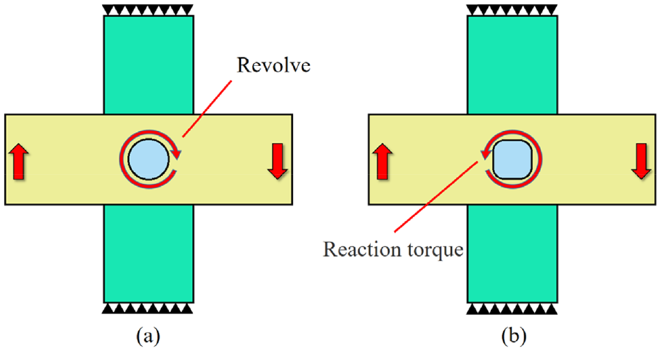
Comparison of anti-torsion performance: (a) round joint and (b) square joint.
In the present investigation, the square clinching process with extensible die was studied experimentally. The main geometrical parameters affecting the static mechanical strength of the square joints were determined. The strength tests of 2 mm thick 5052 aluminum alloy sheets under different forming loads were carried out with the square dies. The failure modes and absorbed energy of the square joints under different forming loads were analyzed. Scanning electron microscope was employed to investigate the microscopic characteristics of the square joints. The results showed that it was effective to join Al5052 sheets by the square tools.
Principle of the square clinching process
The mechanical interlock is produced via plastic deformation of the upper and lower sheets after being squeezed in the square clinching process. The sheets are joined to each other by a mechanical interlock generated by the material flow. As depicted in Figure 2, the square clinching process goes through three stages: (a) the initial position, (b) the punch moves downwards and the sheets generate localized plastic deformation, and (c) mechanical interlock forming. Figure 2(d) shows the forming situation of the diagonal mechanical lock of the square joint.
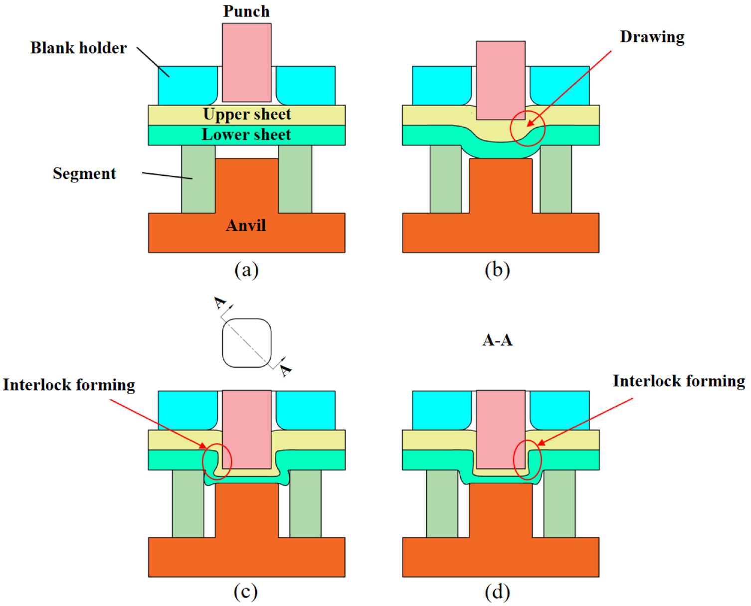
Square clinching process: (a) the initial position, (b) drawing, (c) mechanical interlock forming, and (d) diagonal mechanical interlock of the square joint.
Initially, the upper sheet begins to deform plastically as the punch presses down. The lower sheet also starts to deform under the compression of the upper sheet. The sheet material flows into the cavity and forms a preliminary joint shape under the constraint of the die. With the uninterrupted pressing of the punch, the lower sheet comes into contacting with the anvil. Constrained by the anvil, the sheet material flows around, forming an interlock to join sheets.
The forming process of the square joint is basically the same as that of the conventional round joint. The mechanical interlock the square joint is mainly formed by the plastic deformation of the upper and lower sheets. Thus, the main parameters that affect static strength of the joint are also the geometric sizes of the mechanical interlock. The geometric sizes include the bottom thickness (X), the interlock (ts), and the thickness of the neck (tn), as depicted in Figure 3.
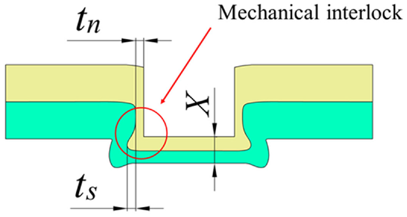
Main geometrical parameters of the square clinched joint.
Materials and methods
Materials
Aluminum alloy has been better developed and applied under the background of lightweight. Al5052 sheets were chosen for the square clinching tests. The mechanical properties of the sheets were tested using the MTS 322 T-type bench testing machine. The stress-strain curve of AL5052 is plotted in Figure 4. Tensile strength of Al5052 is 228.6 MPa, yield strength is 158.7 MPa, and elongation at rupture is 16.48%. There were two sizes of aluminum alloy sheets: the sheets with a size of 80 mm (length) × 25 mm (width) were used for tensile tests, and the sheets with a size of 100 mm (length) × 25 mm (width) were used for the shearing test. The thickness of all Al5052 sheets applied in this study is 2.0 mm.
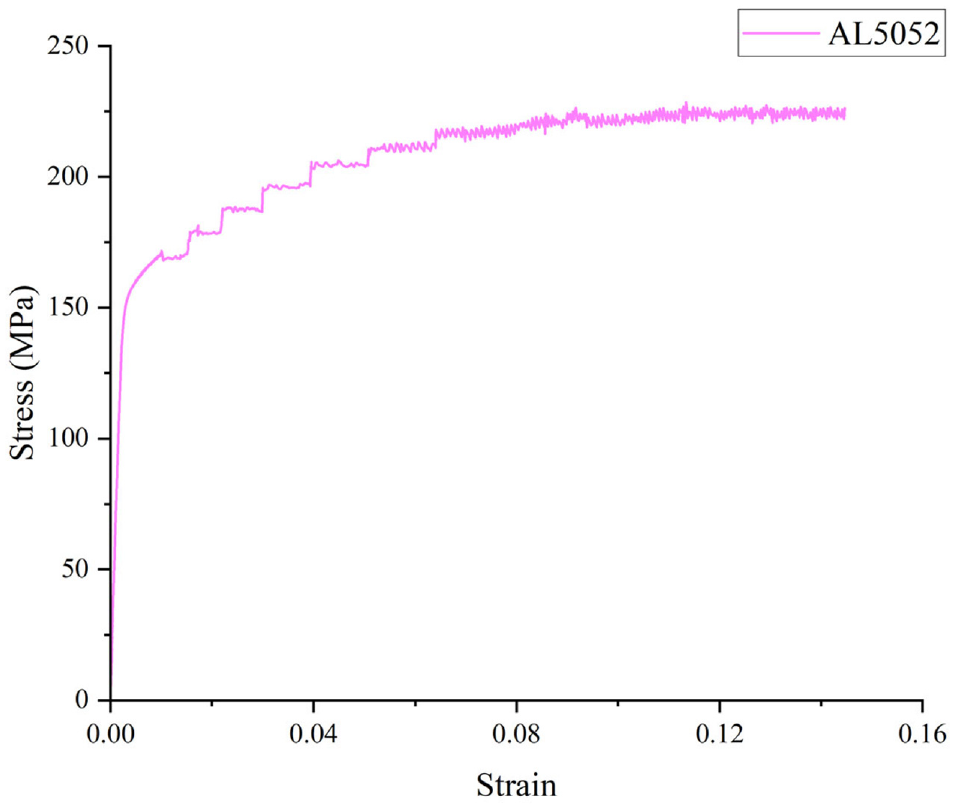
Stress-strain curve of sheet material.
Forming conditions
The square clinching tests were carried out on the Sust CMT-5105 GJ electronic universal testing machine. The square clinching tools consist of four parts: punch, blank holder, segments and anvil, as depicted in Figure 5. The segments are composed of four identical parts, which are wrapped by elastic parts. Compared with the groove die, the extensible die requires less forming force, which is more conducive to the fluidity of materials in the die cavity. Mechanical clinching experiments were carried out with forming forces of 15, 20, 25, 30, and 35 kN. The punch speed was adjusted to 2 mm/min to join the sheets.
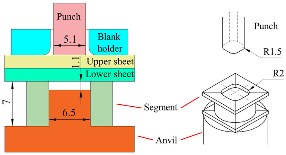
Schematic diagram of the square clinching tools.
Cross sections of mechanical interlock
Various forming loads were set to join Al5052 sheets together. Thus, the geometric parameters of mechanical interlock appear to be vital in this research. The diamond wire cutting machine was used to cut the joint respectively along the side and the diagonal of the joints to obtain the profiles of the joints. The geometric parameters of the mechanical interlock of the joint were observed and measured by an optical electron industrial microscope.
Static strength tests
To test the static strength of joints, shearing and tensile tests were often used. In these tests, an electronic universal testing machine can be applied to measure the maximum load that the joint can bear. The test speed is set to 2 mm/min. Three specimens for each condition were tested to assure the correctness of the test results, and the average strength under each forming condition was calculated.
Sheets with a size of 80 mm × 25 mm were applied to the tensile test, which were joined in a cross-lap form, as presented in Figure 6. The square clinched joint was placed in the center of the overlapping part of the sheets. The tensile test required a pair of special fixtures to fix the cross-shaped sheet and stretch it until the joint was failed.
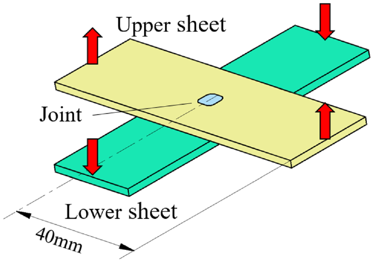
Specimen utilized for tensile tests.
As presented in Figure 7, the specimens applied in the shearing test were of single-lap type. 33 The shearing test applied the sheets with a size of 100 mm × 25 mm. Fixed both ends of the specimens with fixtures and stretched them until the joints were broken.
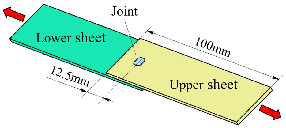
Specimen used for shearing tests.
Results
Forming process
The material flow during the square clinching process brought the cross section of the joint constantly to change. The mechanical interlock forming conditions in the side and diagonal of the joint were inconsistent due to the square shape of the punch. Figure 8 shows the cross-sectional shape of the joint side under different forming forces, which more intuitively reflects the forming process of the square clinched joints. Figure 9 presents the diagonal profile of the square clinched joint. It is evident that there is a greater interlock value and neck thickness in the joint side.
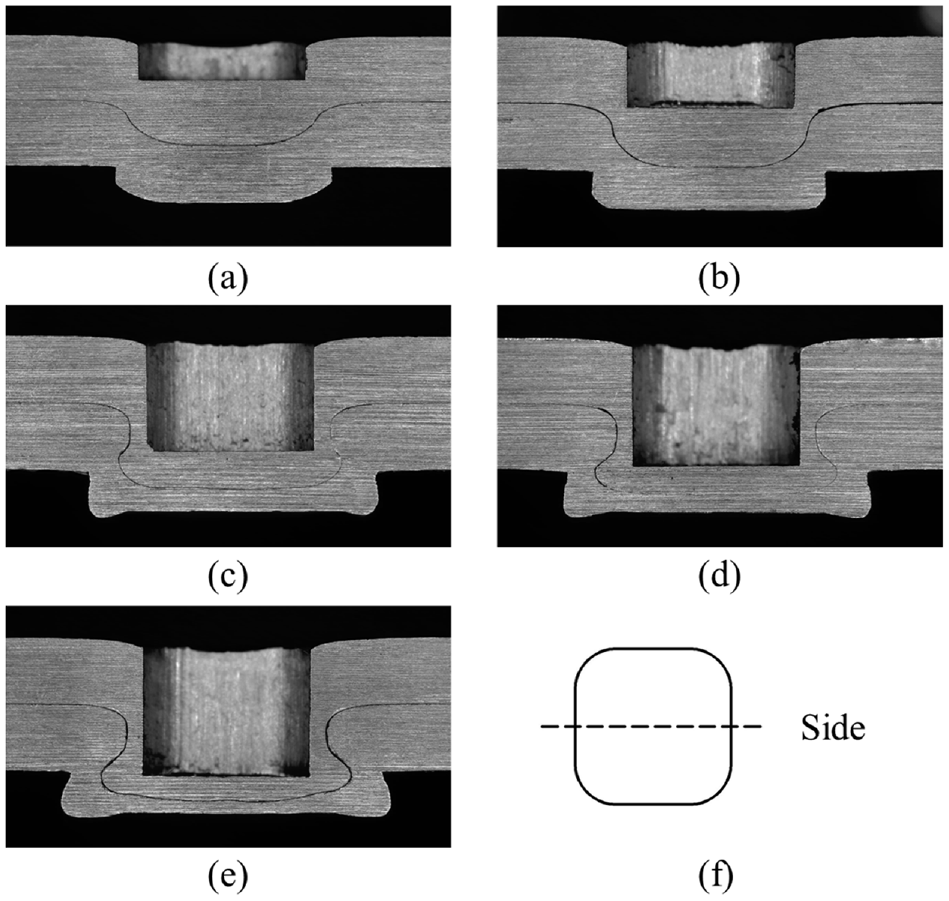
Side profile of the square joints formed by different forming forces: (a) F = 15 kN, (b) F = 20 kN, (c) F = 25 kN,(d) F = 30 kN, (e) F = 35 kN, and (f) cutting direction diagram.
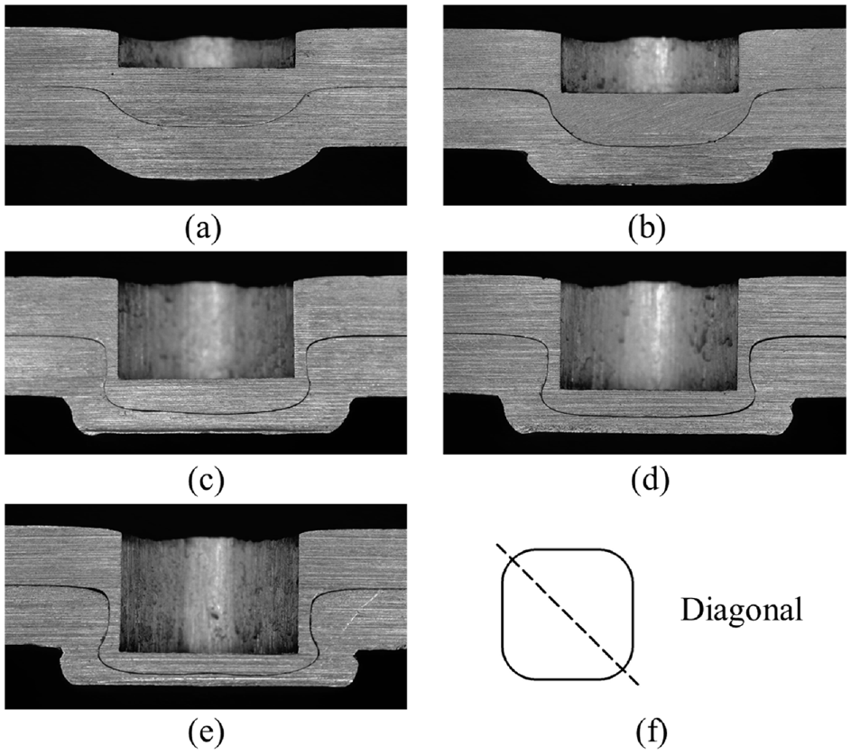
Diagonal profile of the square joints formed by dissimilar forming forces: (a) F = 15 kN, (b) F = 20 kN,(c) F = 25 kN, (d) F = 30 kN, (e) F = 35 kN, and (f) cutting direction diagram.
It can be seen from the section that there is no effective mechanical interlock formed under the forming force of 15 and 20 kN. For this reason, no effective connection can be generated between the sheets. For joints with the forming load between 25 and 35 kN, the deformation of the material is adequate to yield a mechanical interlock, realizing the connection of the sheets.
As the punch moved down, the sheets deform downward. The more the punch pressed down, the more severe the material deformation was. The existence of the anvil restricted the continuous downward flow of the material. Mechanical interlock gradually took shape with the upper sheet was embedded in the lower sheet. The extensible die was employed in this study, and there was no restriction on the sliding distance of the segments. The material always flowed in the direction with the least restriction, forming a larger interlock.
Geometric parameters of the joint section
For the square clinching, the geometric parameters of the mechanical interlock on the joint section, including the interlock, the thickness of the neck and the thickness of the bottom, are the key factors for the evaluation of the joint static strength. As mentioned earlier, an effective connection between sheets cannot be achieved under the forming force of 15 and 20 kN, and hence it would not be considered in the following research. The geometric parameter values of the joint mechanical interlock formed under the forming force of 25, 30, and 35 kN are shown in Figure 10. From the measurement results, the neck thickness of the joint was basically the same, and there was no variation with the change of the forming load. For example, the joint neck thickness on the side section was all around 0.48 mm, and the neck thickness of the diagonal section was 0.4 mm approximately. The interlock value increased with the addition of the forming load. On the contrary, the bottom thickness dwindled with the growth of the forming force. The trend of the side parameters was identical with the diagonal parameters.
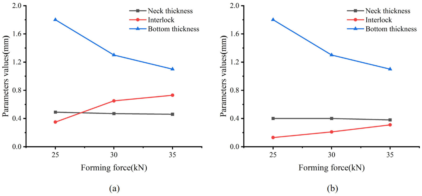
Geometric parameters of the square joints: (a) side section, (b) diagonal section.
As shown in the cross section, although the neck material was under tensile stress, there is no significant reduction in the material of the joint neck after the forming of the mechanical interlock. A slight variation occurred in the thickness of the neck. In the meantime, the bottom thickness of the square joint continued to decrease. The material flowed radially toward the interlocking area. As a result, the interlock value rose.
Static mechanical properties
Static shearing strength
The Sust CMT-5105 GJ electronic universal testing machine was used for shearing tests. For each forming force, three specimens were tested for strength. A continuous load-displacement curve was recorded for each test. The outcomes of the shearing test with various forming loads are depicted in Figure 11. The maximum load that appears during the experiment is the joint shearing strength. It is manifest from the experimental results that the shearing strength of the square joint with the forming load of 25 kN is 1678 N. When the pressing load reaches 30 kN, the peak load is 1687 N. At last, the pressing load of 35 kN brings the joint a shearing strength of 1676 N. As can be seen, the shearing strength of the joints under dissimilar pressing loads is basically the same, and the strength deviation between each other does not exceed 50 N.
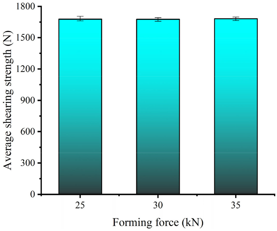
Shearing strength of the square clinched joints.
It can be seen that there is no alteration in the joint shearing strength with the change of the forming load. Meanwhile, from the measurement results of the geometric parameters, there is no significant change in the neck thickness of different square joints. The difference between the thicknesses of the necks is no more than 0.03 mm.
The shearing load-displacement curves of diverse forming forces are plotted in the same coordinate system so as to facilitate comparison, as shown in Figure 12. Similarly, the shapes of the shearing load-displacement curves between distinct pressing forces are basically consistent.
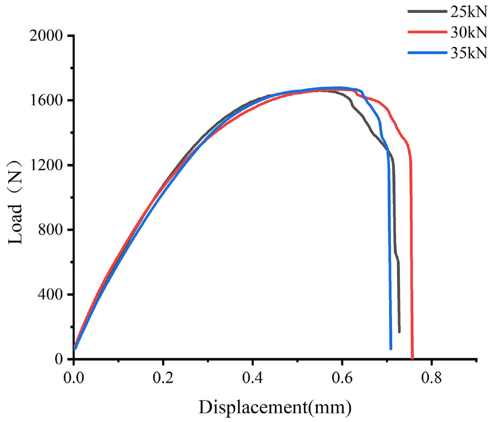
Shearing load-displacement curves of the square joints.
Static tensile strength
The tensile test was carried out on the electronic universal testing machine. Record the tensile load and displacement curve of each sample. The load corresponding to the highest point of the curve is the tensile strength of the square joint. Figure 13 depicts the tensile strength of the square joints under various forming forces.
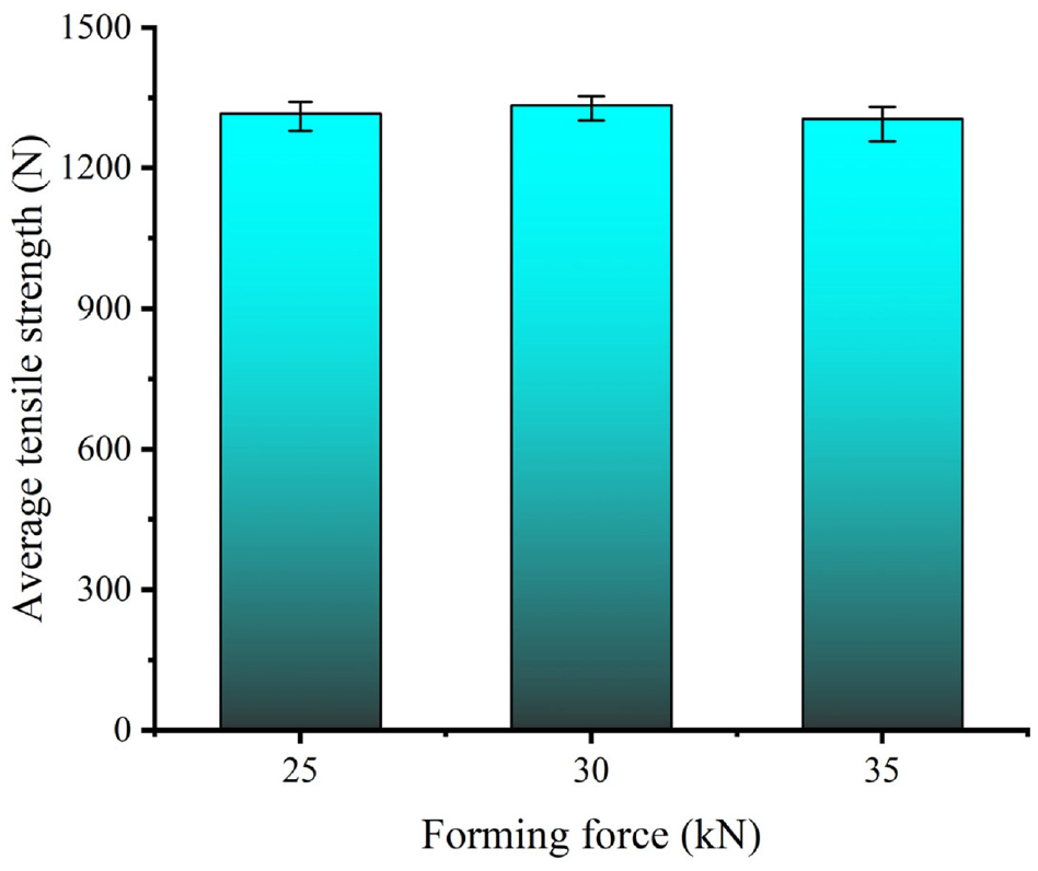
Tensile strength of the square joints.
As stated by the experimental result, the tensile strength of joints under diverse forming forces decreases slightly with the increase of the forming force. However, the mutual deviation is no more than 50 N. Therefore, it can be considered that the tensile strength is basically the same under dissimilar forming forces. Similarly, the occasion for this phenomenon is that the neck thickness of the square joints is consistent with each other.
The load-displacement curves of the joints during the tensile experiment are exhibited in Figure 14. The curves of various forming forces are drawn in the same coordinate system to facilitate comparison.
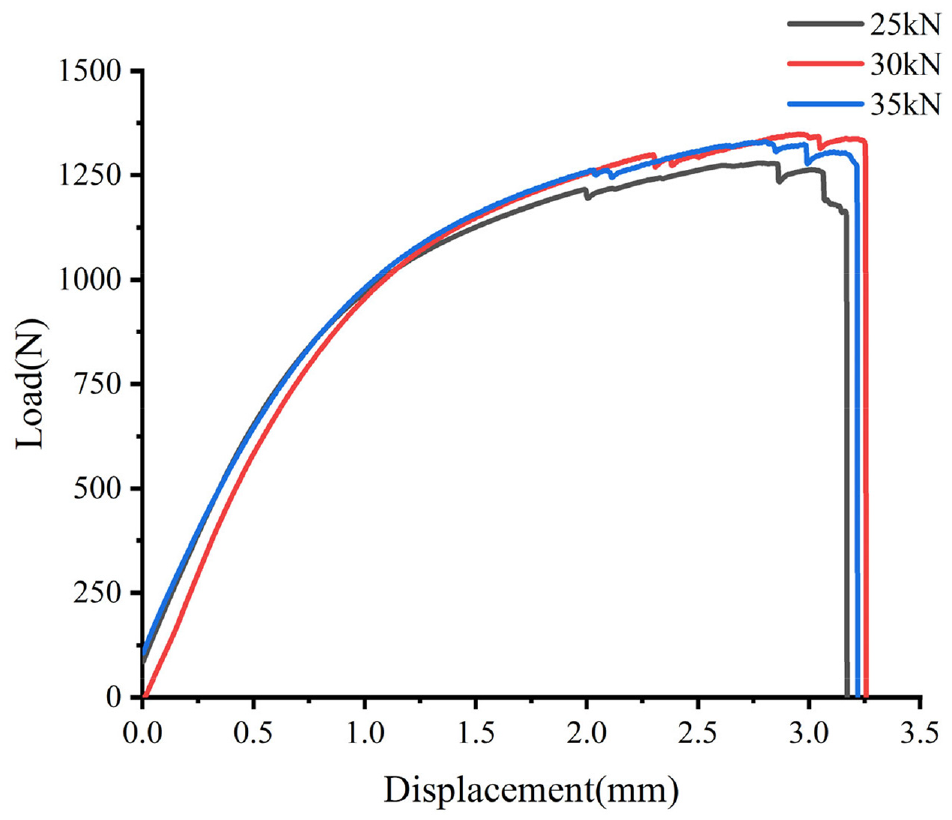
Tensile load-displacement curves of the square joints.
Failure mechanism
At the time that the square joints are subjected to excessive load, the joints will be completely disconnected. There are three main failure modes of joints: shearing failure, tensile failure and fatigue failure. 34 Tensile failure mode mainly encompasses neck fracture mode and button separation mode. For shearing failure mode, the failure of the joints mostly occurs in the neck. When the load on the square joint exceeds the tensile strength limit of the material itself, cracks appear in the neck, which expand constantly and eventually break, resulting in the failure of the joint.
In the shearing test, the failure modes of joints with various forming loads were all neck fracture modes. The neck of the joint was subjected to shearing force. When the shear stress increased to a certain value, cracks appeared on the neck of the upper sheet and gradually spread. Finally, the joints were completely disconnected, as described in Figure 15.
Neck fracture mode in the shearing test.
A TESCAN MIRA3 LMU SEM was utilized to study the micro morphology of the joint fracture in the strength test. In the shearing test, the micro morphology of five typical positions on the joint fracture was observed and analyzed, as shown in Figure 16. Shearing dimples with significant directionality are both distributed in areas a, c, e and f, formed by microporous polymerization shear. A large number of parabolic-shape shear dimples are distributed in area a, surrounded by plenty of small dimples, as shown in Figure 16(a). In area d, the micro surface is relatively smooth and there is basically no dimple, which illustrates that there is not much plastic deformation in this area during fracture. Dense and deep conical dimples appear in area e. The edges of shear dimples in area f are short and dense. Sparse and large shear dimples are distributed in area c, and a small number of microspores and second phase particles are also present on the surface. The fracture surface of the shearing sample shows typical shear ductile fracture.
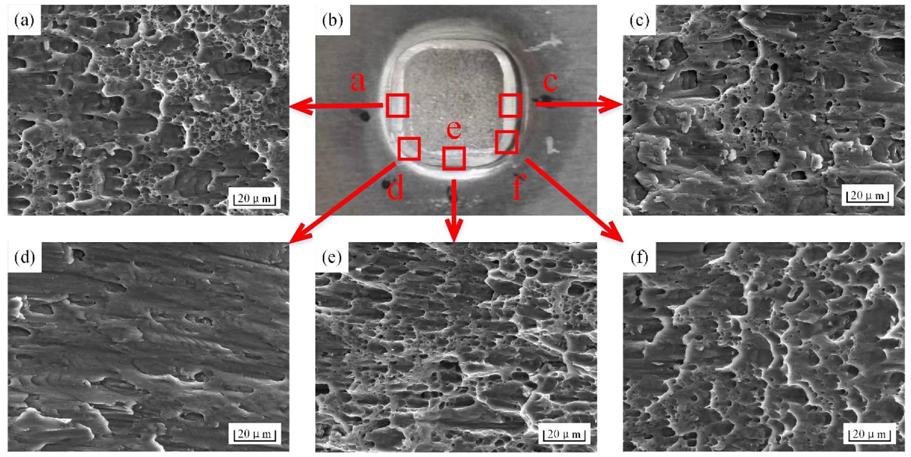
Microscopic structure of the joints in shearing tests: (a) zone a, (b) macro view, (c) zone c, (d) zone d, (e) zone e, and (f) zone f.
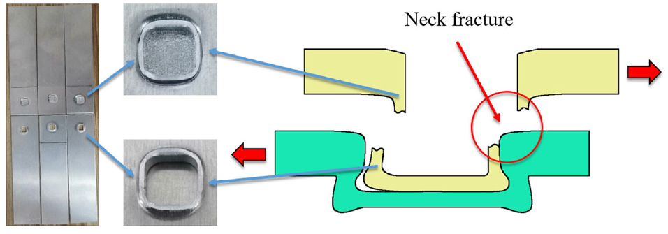
The weak neck of the joint easily causes failure to occur in the neck. On the contrary, a small interlock value will easily cause the upper and lower sheets to separate from each other without breaking. Similarly, in the tensile test, the failure modes of the joints were all neck fracture modes, as shown in Figure 17. The tensile stress reached the tensile strength limit of the neck material, cracks grew and expanded, and then the neck was completely cut off.
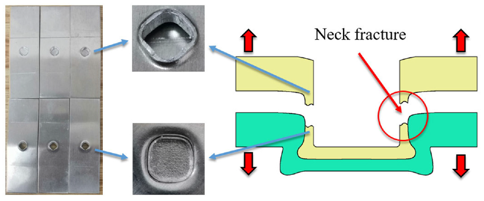
Neck fracture mode in the tensile test.
Figure 18(c) shows the macro morphology of the joint fracture in the tensile test. The macroscopic profile of areas a, b and d is parallel to the direction of maximum shear stress. Dimples elongated by shear force can be observed in area a, which are in parabola shape, as presented in Figure 18(a). In addition to parabolic-shape dimples, a large number of equiaxed ductile dimples with different sizes appear in area b. There are plenty of large and deep approximately circular dimples in area d, which belongs to typical microporous polymerization fracture, as depicted in Figure 18(d). Large and deep dimples in area d mean that more energy can be absorbed before fracture. Under the action of tensile stress, the joint employed for tensile test first breaks in area a. Then, cracks spread to area b and finally breaks completely in area d.
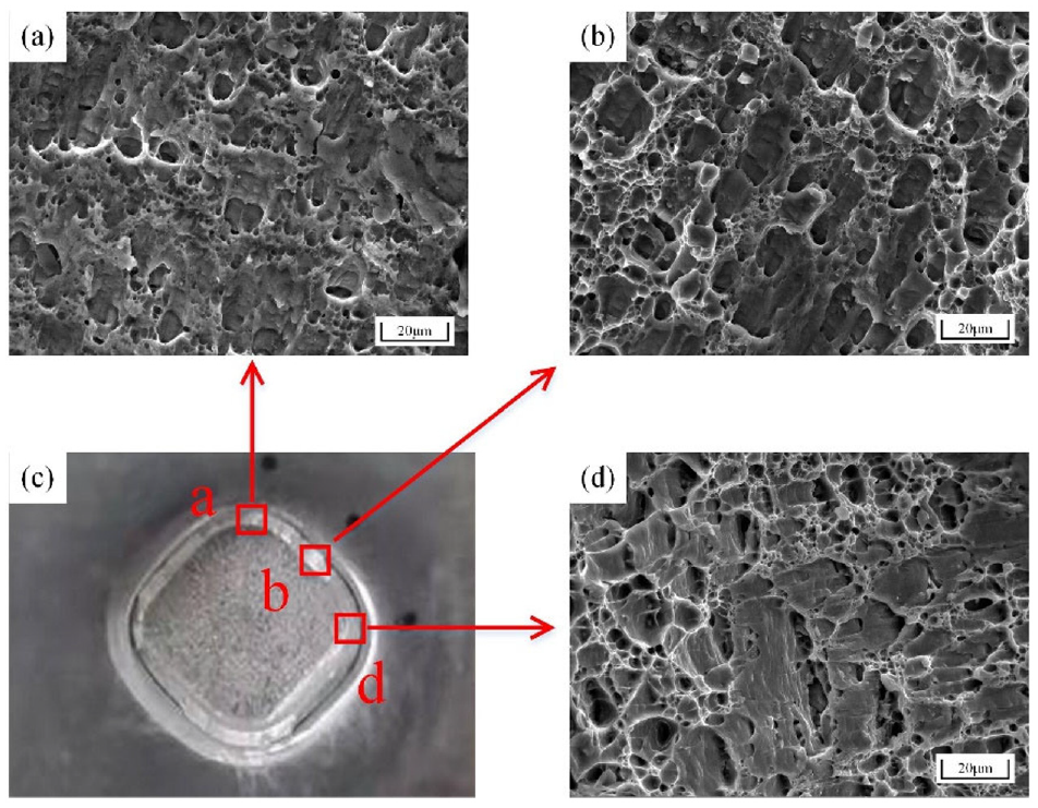
Microscopic structure of the joints in tensile tests: (a) zone a, (b) zone b, (c) macro view, and (d) zone d.
It can be seen that the joint fracture is covered with dimples, which is a typical feature of ductile fracture, in both shearing and tensile tests. However, they have different stress states during the fracture process. In the shearing test, the joint is mainly subjected to tangential stress, so the dimples on the joint fracture show a parabolic-shape with obvious directionality. In the tensile test, the fracture of the joint is nearly circular in shape, and the directionality is not obvious, which is the result of the dominant effect of tensile stress.
Energy absorption
Another performance evaluation criterion for clinched joints is the energy absorption during failure. For instance, the more impact energy the car body absorbs, the higher the safety of the driver in the crash. Therefore, the clinched joints should possess sufficient energy absorption. The more energy the joints absorbed during the failure of the joints, the more reliable the joints would be. The area enclosed by the load-displacement curve and the abscissa of the coordinate system represents the joint absorbed energy during the joint failure process. The specimens for calculating joint energy absorption are the specimens used for testing the joint shearing strength. In shearing test, the joint energy absorption value is presented in Figure 19.
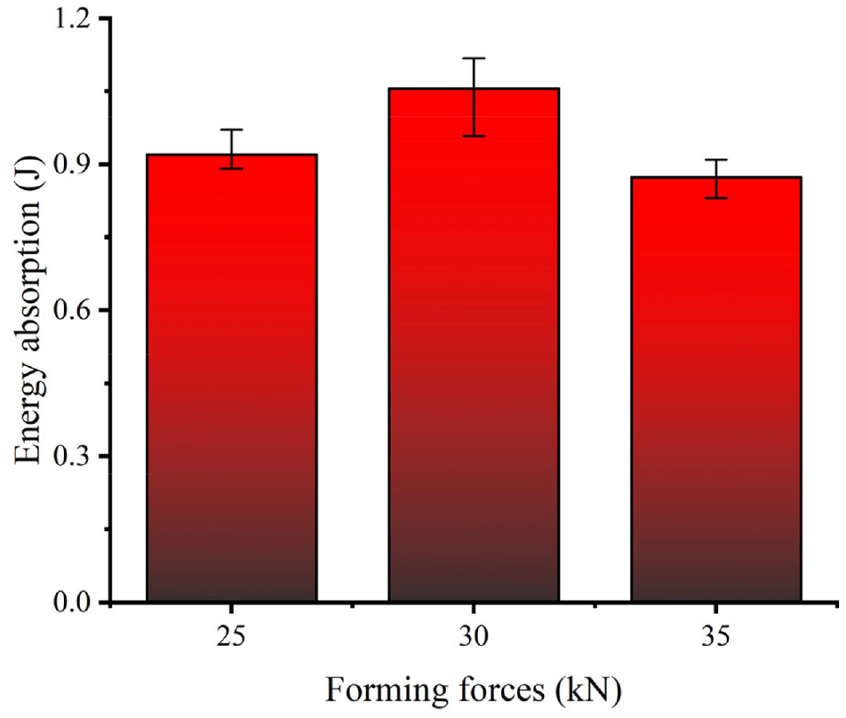
Energy absorption in the shearing test of the square joints.
As can be seen from the figure that the energy absorption value of the joints under the forming load of 30 kN is 1.055 J, which is slightly larger. The absorbed energy value of the joints under the forming force of 35 kN is slightly smaller, which is 0.873 J. The dissimilarity in shearing absorbed energy of joints under different forming forces is no more than 0.2 J.
Discussion
The interlock can be formed on the cross sections in various directions of the square joints. However, forming conditions are discrepant in different positions. In the diagonal section, both the neck thickness and the interlock are smaller than the side section. After the material is under pressure, it tends to change evenly around. However, the round surface of the square punch is farther from the center, which may cause larger material stress during forming. The side material obtains lower resistance and forms a mechanical interlock with greater parameters.
For the failure mode of the joint, regardless of whether the joints are stretched or sheared, the failure of the joint mostly occur in the neck. It can be found that the interlock value of the square joint is greater than the neck thickness of the square joint, that is, the bearing capacity of the joint interlock is stronger. Consequently, the joint strength is determined by the neck thickness of the joint. The load acts on the neck, and the thinnest part of the neck becomes thinner by shearing or stretching. Fracture occurs in the joint neck, while the load reaches the tensile limit of the thinnest neck. In addition, the joint fracture showed typical ductile fracture characteristics in both tensile and shearing tests.
There is little difference in the strength of joints formed under different forming forces. The clinching process is carried out at room temperature and does not involve chemical reactions. The strength of the joint is determined by joint geometric parameters such as neck thickness and interlock value. The interlock value and the bottom thickness of the joint change significantly with the expansion of the forming force. However, there is no conspicuous variety in the neck thickness of the joint. The formation of the interlock is basically without the involvement of the neck material, and most of the material flowing to the interlock comes from the bottom of the joint. In addition, the failure of all joints in this test occurs at the neck of the joint. This indicates that the neck thickness of the joint in this study is the decisive factor affecting the tensile and shearing strength of the joint. From the joint profiles, it can be seen that the neck thickness of the joint does not change with the variation of the forming force. To this end, the tensile and shearing strength of the joint under different forming forces are basically the same. In addition, the changing trend of the joint energy absorption capacity under various forming forces is consistent with the trend of joint strength. For instance, the shearing energy absorption value of the joint alters little during the experiment, which is similar to the shearing strength of the joint.
Conclusions
In the present study, the square clinched joints were investigated experimentally under various forming forces. The square clinching tools with the extensible dies were employed to produce square joints. The shearing and tensile tests were applied to evaluate the static mechanical properties of the joints. The main geometric parameters affecting the mechanic characteristics of the square joints were ascertained. The failure mode and energy absorption were analyzed. The square clinching process can join the Al5052 sheets reliably. The main conclusions of this paper can be epitomized as follows:
When the forming force is between 25 and 35 kN, the square clinched joint can produce mechanical interlocks in the cross section of diverse directions to hook the upper and lower sheets. In addition, although the interlock is formed on the side and the diagonal, the geometric parameters of the mechanical interlock in the diagonal are relatively small.
There is almost no remarkable flow of the neck material after the forming of the interlock. With the increase of pressing load, the interlock value of the square joint grows constantly, and meanwhile the neck thickness is basically the same.
In tensile and shearing experiments, all the failure modes of square joints are neck fracture mode, which means that the square joint strength is decisively affected by the thickness of the joint neck. Moreover, the joint fracture showed typical ductile fracture features.
The square clinched joints under different forming forces maintain basically the same strength during the shearing and tensile experiments due to the slight change in the thickness of the neck. Similarly, there is no variation in the energy absorption capacity of the joint under different forming conditions.
Footnotes
Declaration of conflicting interests
The author(s) declared no potential conflicts of interest with respect to the research, authorship, and/or publication of this article.
Funding
The author(s) disclosed receipt of the following financial support for the research, authorship, and/or publication of this article: This research work is supported by the National Natural Science Foundation of China (Grant No. 51805416), Young Elite Scientists Sponsorship Program by CAST (Grant No. 2019QNRC001), Hunan Provincial Natural Science Foundation for Excellent Young Scholars (Grant No. 2021JJ20059), Huxiang High-Level Talent Gathering Project of Hunan Province (Grant No. 2019RS1002), and the Project of State Key Laboratory of High Performance Complex Manufacturing, Central South University (Grant No. ZZYJKT2022-01).