
Abstract
Together with machining chatter, surface location error induced by forced vibration may also inhibit productivity and affect workpiece surface quality in milling process. Addressing these issues needs the combined consideration of stability lobes diagram and surface location error predictions. However, mode coupling and process damping are seldom taken into consideration. In this article, an extended dynamic milling model including mode coupling and process damping is first built based on classical 2-degree-of-freedom dynamic model with regeneration. Then, a second-order semi-discretization method is proposed to simultaneously predict the stability lobes diagram and surface location error by solving this extended dynamic model. The rate of convergence of the proposed method is also investigated. Finally, a series of experiments are conducted to verify the veracity of the extended dynamic model. The modal parameters including direct and cross terms are identified by impact experiments. Via experimental verification, the experimental results show a good correlation with the predicted stability lobes diagram and surface location error based on the extended dynamic model. Also, the effects of mode coupling and process damping are revealed. Mode coupling increases the whole stability region; however, process damping plays a vital role in stability improvement mainly at low spindle speeds.
Keywords
Introduction
Increasing demands on manufacturing precision products require high-efficiency and high-accuracy machining.1,2 Tool path optimization and machining parameters’ optimization are two common technologies that meet the demands. For tool path optimization, Li and colleagues3,4 constructively proposed a rank 2 tensor–based global optimal tool path generation method, which can effectively improve the machining efficiency of the workpiece with complex free-form surfaces. Sun et al. 5 proposed a smooth tool path generation method for five-axis machining of triangular mesh surface with nonzero genus. For machining parameters’ optimization, the researches mainly focus on the prediction of stability lobes diagram (SLD) and surface location error (SLE).6,7 Because both chatter and forced vibrations have a great effect on machining process, they may degrade machining performance and deteriorate workpiece surface quality. Guo et al. 8 studied SLD in milling with multi-delays considering helix angle effect. Shi et al. 9 predicted SLD for face milling processes considering the dynamic interaction between cutting tool and workpiece. Schmitz and colleagues10,11 revealed the effect of helix angle and run-out on SLE. Generally, the combined consideration of SLD and SLE is important for choosing optimal machining parameters.
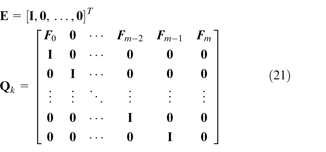
Mathematically, classic dynamic milling model based on regeneration can be formulated as delay differential equations (DDEs) with time-varying coefficients. By solving this type of equation, the SLD and SLE can be obtained. Throughout the past few decades, tremendous efforts have been made for accurately and efficiently predicting SLD and SLE. For SLD prediction, a lot of remarkable methods have been proposed such as zero-order analytical (ZOA) method, 12 temporal finite element analysis (TFEA) method, 13 multi-frequency solution (MFS), 14 semi-discretization method (SDM),15,16 full-discretization method (FDM),17,18 and Runge–Kutta methods. 19 For SLE prediction, the major algorithms focus on numerical simulation method, 20 frequency domain method, 10 harmonic balance method, 21 TFEA, 22 and FDM. 23 Especially, TFEA and FDM can achieve simultaneous predictions of SLD and SLE.
However, mode coupling and process damping were not taken into account in the above works. As is well known, regenerative chatter is the most familiar form of self-excited vibration, which appears as a time-delay item in the chip thickness equation from the modeling standpoint. Likewise, mode coupling is also an indispensable chatter mechanism which results from the coupled effect among the natural frequencies of the different vibration modes.24,25 Tlusty and Polacek 26 first discussed that chatter may occur owing to non-regenerative mechanisms such as mode coupling. Gradišek et al. 27 revealed that even weak mode coupling influences the predicted stability boundary greatly via numerical simulation. Zhang et al. 28 found that mode coupling and regenerative effect actually co-exist during the practical milling process, and the usually neglected mode coupling has a great effect on the stability boundary. Recently, Lu et al. 29 studied the effects of tool orientation on the five-axis milling process stability with flat-end cutters, and the formulation for the dynamic milling system is developed by simultaneously considering mode coupling and regenerative effect. Apart from mode coupling, process damping originating from the interaction between tool and workpiece has also been one of the hot issues in machining dynamics.30,31 Process damping is well known as a beneficial phenomenon that may suppress chatter and increase stability, especially in low-speed milling of difficult-to-machine materials such as titanium and nickel alloy. Given its complicated mechanism, most of the previous researches ignored this beneficial phenomenon when modeling the dynamic milling process. However, this small negligence may lead to significant errors in stability prediction at low spindle speeds. Wu 32 modeled process damping forces as a function of the tool flank–workpiece indentation volume and a material dependent coefficient. Subsequently, the principal research work focused on the coefficient calibration and indentation volume calculation. Chiou and Liang 33 approximated the indentation volume as a function of cutting speed, vibration velocity, and wear land length in the case of small amplitude vibration. Ahmadi and Ismail34,35 analytically derived the computation procedure of indentation volume and integrated equivalent linear viscous damper of process damping into the MFS and SDM to obtain the SLD in milling. Tunç and Budak 36 proposed a practical identification method for process damping coefficient through energy balance formulation. The theoretical expressions of indentation volume is established by including some important geometrical parameters such as tool hone radius, clearance angle, separation angle, and geometry of clearance face. Ahmadi and Altintas 37 presented an identification method based on frequency domain decomposition, where process damping coefficient was estimated using vibrations measured at two locations of the tool during chatter free orthogonal turning tests. They calculated wear land length as the summation of three segments by considering the effects of hone radius, separation angle, and clearance angle. Recently, Wan et al. 38 proposed a generalized method for exploring the plowing mechanism of both static and dynamic cuts. The process damping coefficient can be directly identified using the static plowing forces, which are separated from the measured milling forces.
In this article, an extended dynamic model of the milling process with mode coupling and process damping is presented. It is noteworthy that SDM can be applied here due to its versatility in analysis of advanced milling models. Hence, a second-order SDM is proposed to simultaneously obtain the SLD and SLE by solving the extended dynamic milling model. The remainder of this article is organized as follows. Based on classical 2-degree-of-freedom (2-DOF) dynamic milling model with regeneration, an extended dynamic model including mode coupling and process damping is first built in section “Extended dynamic milling model with mode coupling and process damping.” In this extended dynamic model, regenerative effect varies instantaneous uncut chip thickness which, in turn, generates a variable cutting force. Process damping effect is described with an equivalent linear viscous damper model in Ahmadi and Ismail, 34 and the cross terms of modal parameters are nonzero when mode coupling is considered. Through further transformation, the extended dynamic model in the state-space form can be obtained for the convenience of solution. In section “Milling stability and SLE analysis,” a second-order SDM is proposed by approximating time-delay term with second-order Newton interpolation polynomial. Using the proposed method, the extended dynamic model in the state-space form can be solved to simultaneously obtain SLD and SLE via Floquet theory and fixed point theory, respectively. The rate of convergence of the proposed method is investigated through the comparison with the first-order SDM 16 and the second-order FDM. 17 Section “Experimental verification” first calibrates the cutting force coefficients by experiments. The modal parameters including direct terms and cross terms are then identified by impact experiments. Later, a series of experiments are conducted to verify the predicted SLD and SLE based on the extended dynamic model. Also, the effects of mode coupling and process damping are revealed. Section “Conclusion” summarizes the article.
Extended dynamic milling model with mode coupling and process damping
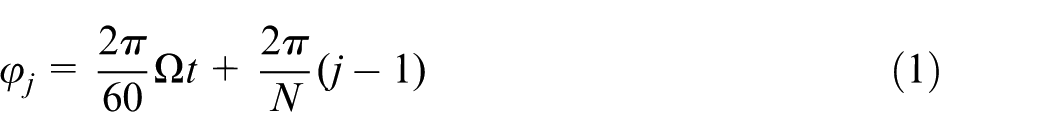
Milling system, as shown in Figure 1, can be regarded to have 2 DOFs in the X and Y directions. The tool is assumed to be flexible with respect to the rigid workpiece. For helical end mills with N teeth and equal pitch angle, the instantaneous immersion angle is actually variable along the axis of the tool. However, considering that the axial cutting depth is small compared with the diameter of the tool, helix angle is ignored according to Altintas. 1 The instantaneous immersion angle of the jth tooth is defined as a function of the spindle speed Ω and time t
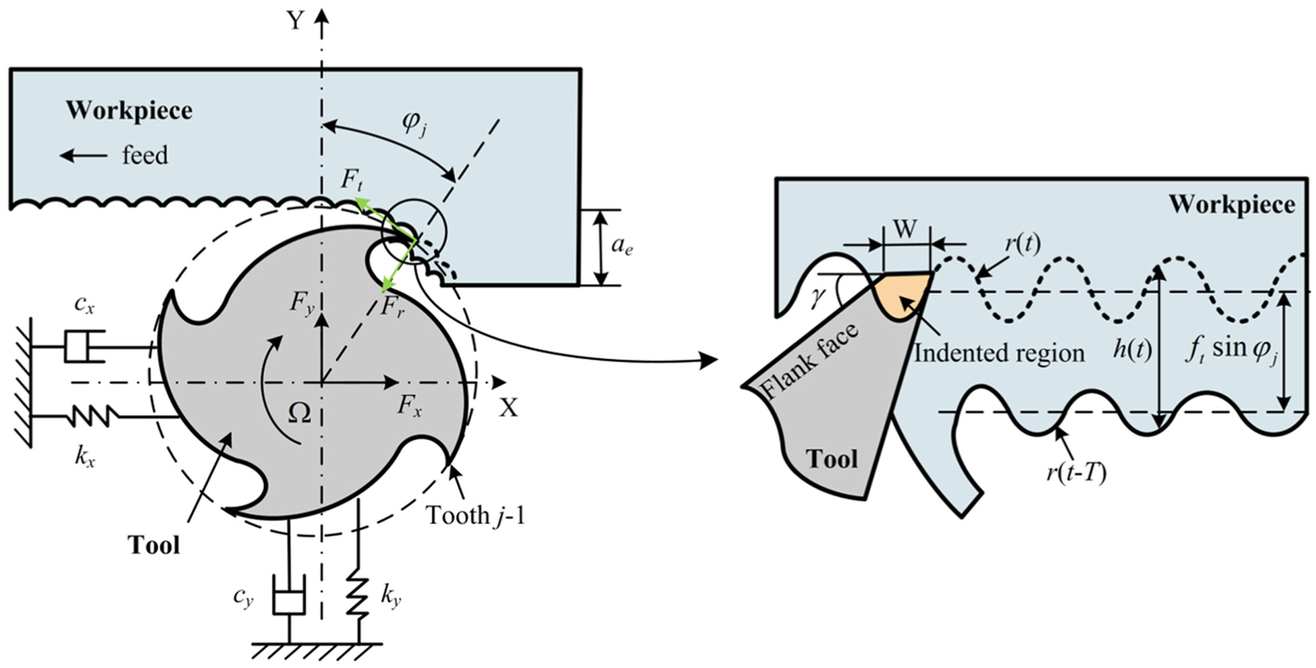
The schematic diagram of 2-DOF dynamic milling system with process damping.
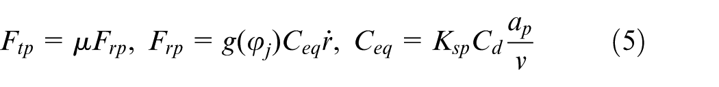
The cutting forces Fr and Ft acting on the jth tooth are attributed to two physical mechanisms: the chip shearing and process damping effect. The shearing forces, with subscript s, are generally supposed to be proportional to the chip area

where ap represents the axial cutting depth. Kt and Kr are tangential and radial shearing force coefficients, separately. The unit step function,

where

where
where
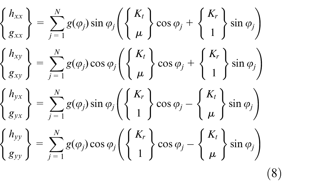
The total cutting forces
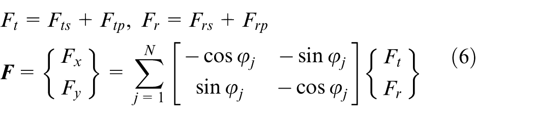
Rearranging the equation of total cutting forces in matrix form yields the following
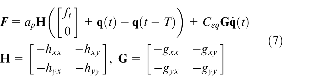
where
The governing equation of this extended 2-DOF dynamic model can be formulated as a DDE, with time-varying coefficients
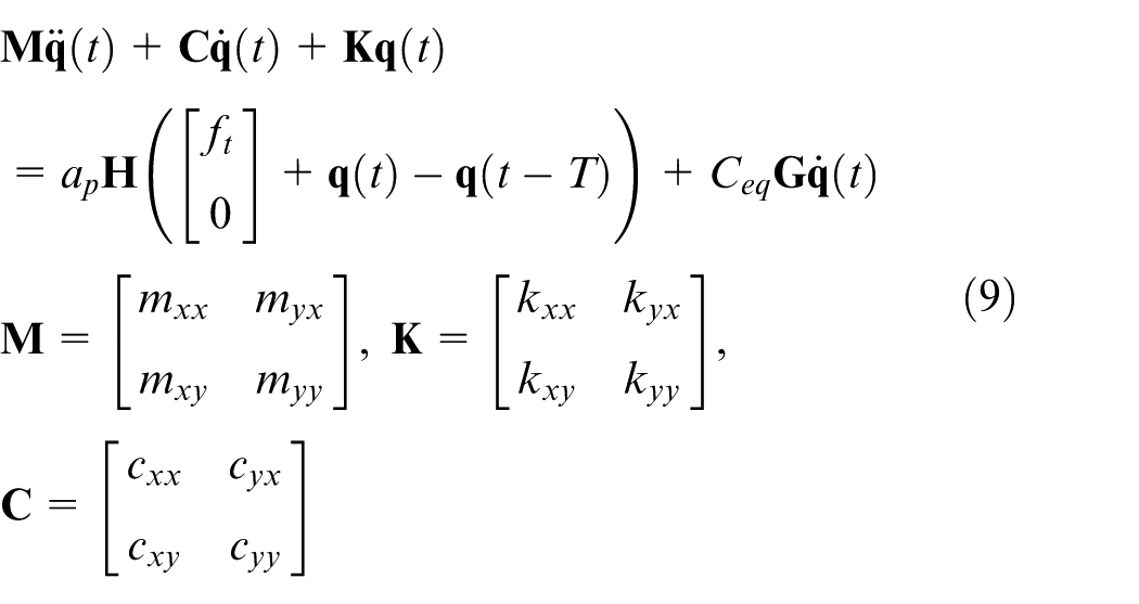
where
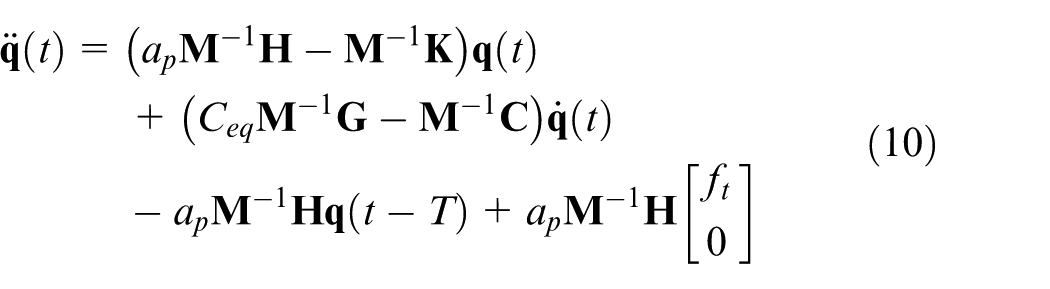
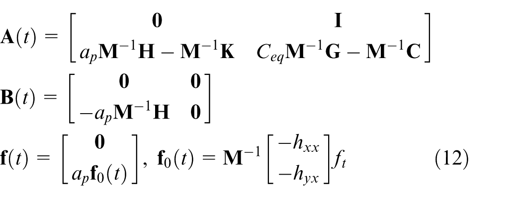
Then, let

where
Milling stability and SLE analysis
Second-order SDM
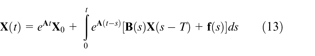
Without loss of generality, the extended dynamic model in the state-space form can be solved by the SDM. In order to keep high computation accuracy, a second-order SDM is proposed to simultaneously satisfy SLD and SLE predictions. Regarding initial condition
First, the time period T is discretized into
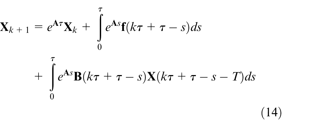
where
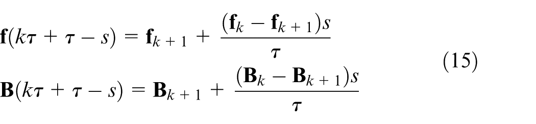
For the sake of improving the approximation accuracy, time-delay term is approximated using the following second-order Newton interpolation polynomial
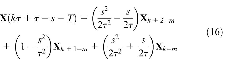
Through further algebraic transformations with equations (15) and (16), equation (14) can be transformed as follows
where
and
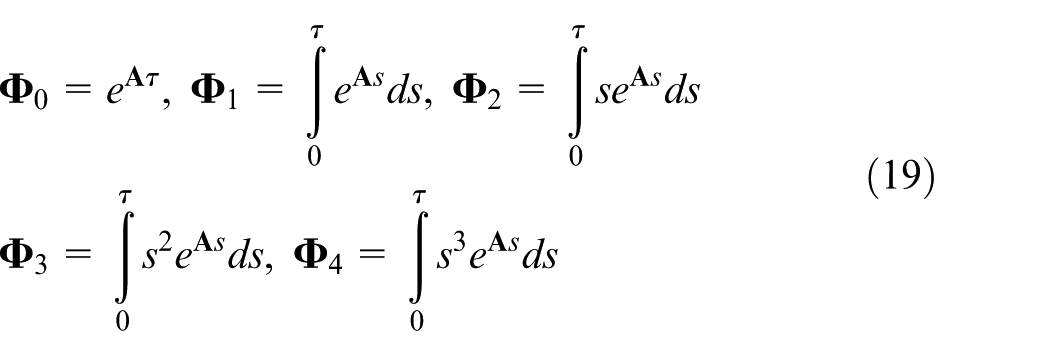
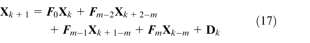
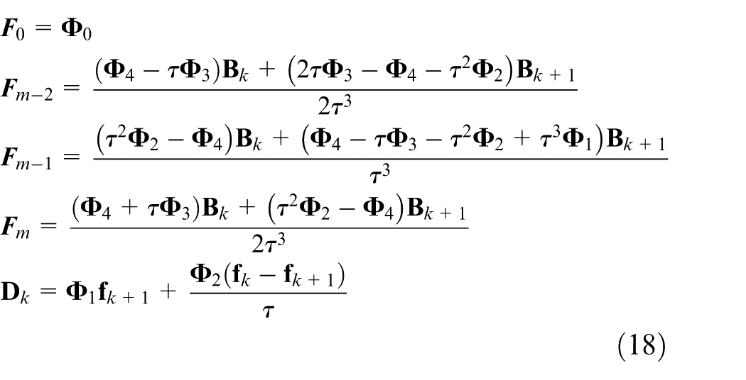
Thus, according to the expanded state vector

where
For one periodic time interval, the SLD can be finally determined using the Floquet theorem with the transition relation constructed as follows

where
For the multiperiod case, the fixed point theory is utilized and the transition relation is described as follows

where

Then, the steady-state coefficients

Finally, the SLE, which corresponds to the entry region for up-milling and exit region for down-milling, can be determined using the steady-state coefficients
Rate of convergence analysis
As a vital evaluation indicator, rate of convergence is widely utilized in recognized algorithms. In this section, the rate of convergence of the proposed method is investigated through the comparison with first-order SDM 16 and second-order FDM. 17 Using the error estimation method, the local discretization errors of the first-order SDM and second-order FDM are both proved as o(τ 3 ). Following the same way, the local discretization error of the proposed method is determined as o(τ 3 ).
In order to achieve a more in-depth analysis of the rate of convergence, a 1-DOF milling system in the study by Insperger and Stépán
15
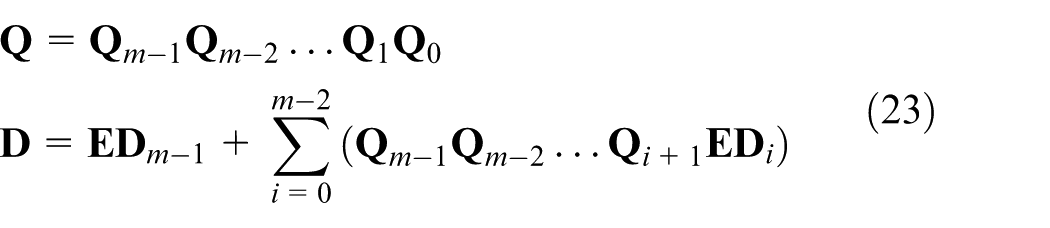
is utilized here as an example, where the cutting conditions and modal parameters are listed in Table 1. Computer programs of the first-order SDM, the second-order FDM, and the proposed method are all written in MATLAB R2014a, and run on a personal computer (PC) (Intel® Core™ i7-4790K CPU, 4.00 GHz, 16 GB). Through calculation, the convergence rate comparisons of above three algorithms at large and low radial immersions are illustrated in Figures 2 and 3, respectively. Note that the label
Cutting conditions and modal parameters
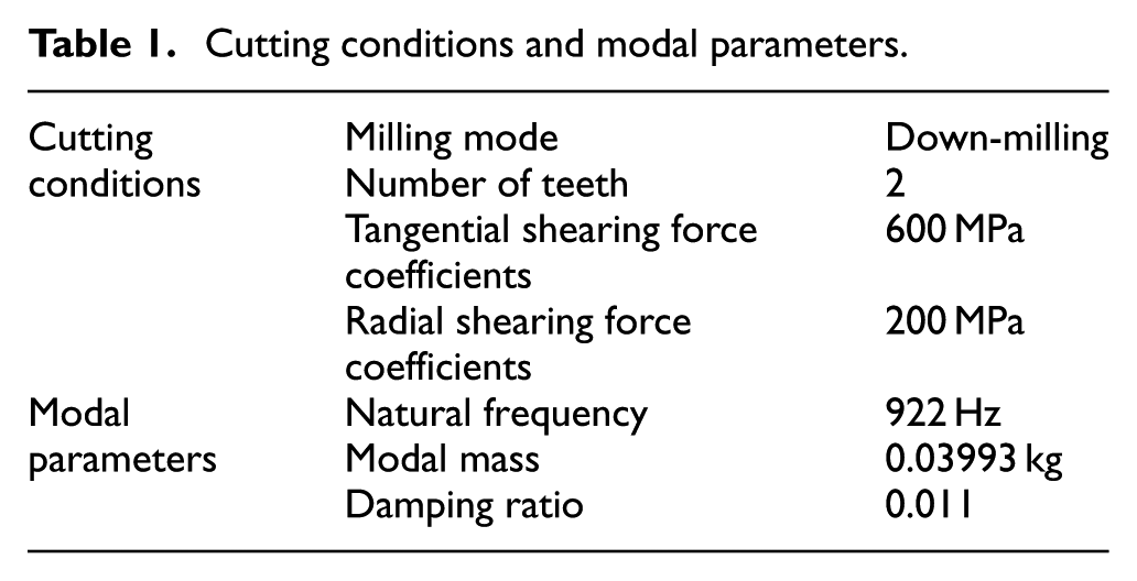
Convergence rate comparisons of the first-order SDM, the second-order FDM, and the proposed method at large radial immersions (radial immersion ratio aD = 1).
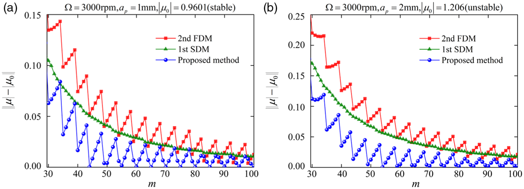
Convergence rate comparisons of the first-order SDM, the second-order FDM, and the proposed method at low radial immersions (radial immersion ratio aD = 0.1).
Experimental verification
In order to verify the veracity of the extended dynamic milling model, the practical experiments are conducted. Prior to calculating the SLD and SLE with the proposed method, the cutting force coefficients and modal parameters must be determined. Later on, almost all the experimental efforts focus on verifying the accuracy of prediction. In light of the accuracy concerns, all the experiments are carried out on the same 5-Axis CNC Vertical Machining Center (DMU 50 DECKEL MAHO).
Cutting force coefficients’ identification
As mentioned in dynamic model, the cutting forces are attributed to two physical mechanisms: the chip shearing and process damping effect. The process damping coefficients mainly depend on the material of the workpiece. According to Tunç and Budak, 36 the specific indentation force coefficient and the coulomb friction coefficient corresponding to titanium alloy (Ti-6Al-4V) are identified as Ksp = 3×10⁴ N/mm3 and µ = 0.3. As for the shearing force coefficients Kt and Kr, the mechanistic approach 40 is put into use. Considering the effect of process damping at low spindle speed, shearing force coefficients are determined at high spindle speed. A helical solid carbide end mill with four teeth, 10 mm diameter, 30° helix angle, and 60 mm overhang length is used during this experiment. The workpiece material is a titanium alloy block and it is machined in full-immersion conditions. The experimental configuration of shearing force coefficients is as sketched in Figure 4, where the experiment systems are made up of Kistler 9257B dynamometer, Kistler 5070A charge amplifier, Kistler 5697A1 data acquisition, and DynoWare software on PC. With the spindle speed and axial cutting depth kept as constant, the feed per tooth ft varies over a range of 0.02–0.10 mm/tooth in increments of 0.02. Averaging the measured cutting forces and implementing linear regression, the shearing forces coefficients can be calibrated as Kt = 2061.9 MPa, Kr = 636.6 MPa.
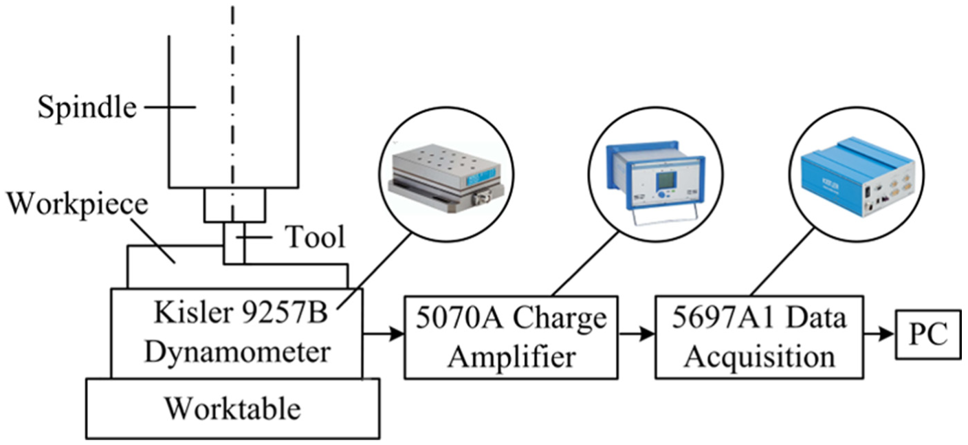
Experimental configuration of shearing force coefficients.
Modal parameters’ identification
Modal impact experiment plays an increasingly essential role in the identification of mechanical structures’ modal parameters, which needs good engineering judgment and experience. Figure 5 shows the impact directions of modal impact experiment, in which the subscripts including x and y mean same as mentioned in dynamic model. Note that the impact experiment is conducted four times at each direction so as to reduce the uncertainty. Also shown in this figure is the schematic diagram of obtaining experimental frequency response function (FRF). Analog signal obtained from sensor is first filtered by anti-aliasing filter. Then, analog signal is converted to digital signal with the function of analog digital converter (ADC). Due to the unavoidable leakage of signal, window function is generally applied. The FRF can be acquired later via fast Fourier transform (FFT).
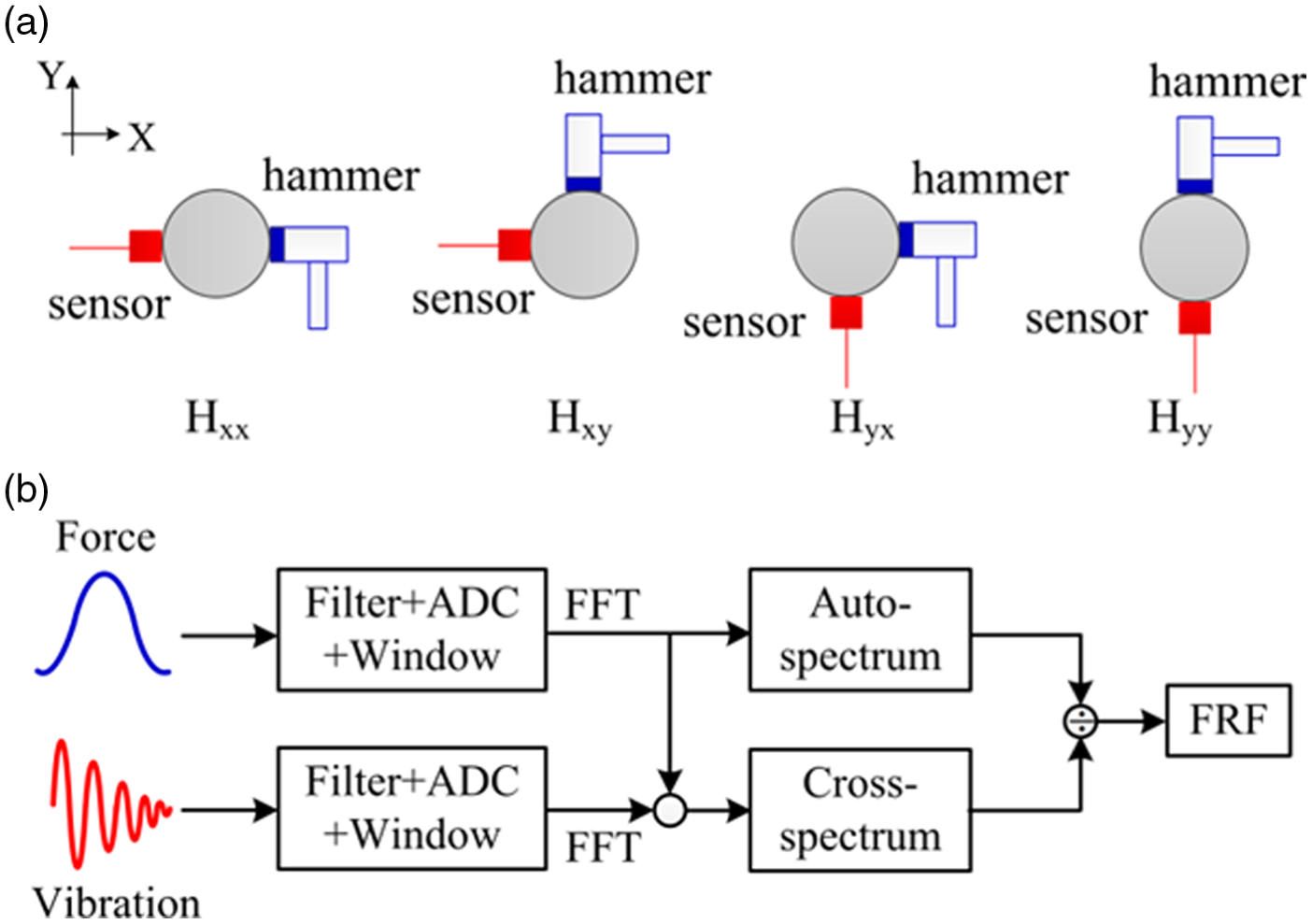
(a) The impact directions of modal impact experiment and (b) the schematic diagram of obtaining experimental FRF.
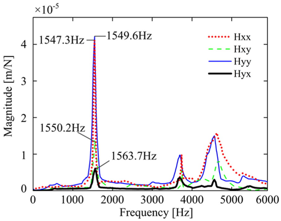
The procedure of modal impact experiment is as follows. An impact hammer with a piezoelectric force transducer is used to excite the tool tip. The corresponding response is measured by an accelerometer, which is mounted at tool tip. Once the data are processed by signal conditioning instrument and data acquisition instrument, the corresponding FRF can be measured by a dynamic signal analysis system. Through further conversion from acceleration to displacement, the measured FRFs (Hxx, Hxy, Hyx, and Hyy) of the tool tip are shown in Figure 5. As can be observed, the most flexible natural frequencies of Hxx, Hxy, Hyx, and Hyy are 1547.3, 1550.2, 1563.7, and 1549.6 Hz, respectively, which are basically equal to 1550 Hz. The magnitudes of cross FRFs (Hxy and Hyx) are smaller than that of the direct FRFs (Hxx and Hyy). This phenomenon indicates that mode coupling indeed exists in the practical milling. The modal parameters are identified by peak picking approach.
2
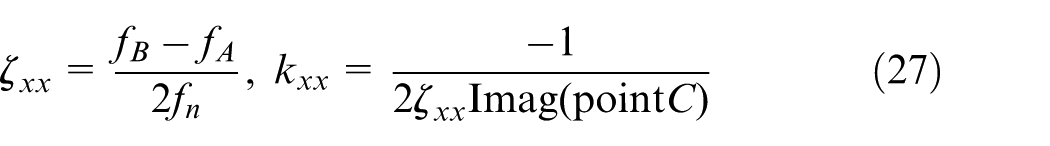
Hxx is selected for an example to illustrate briefly. Figure 6 shows the real and imaginary parts of Hxx. The dominant mode is observed at fn = 1547.3 Hz which corresponds to the lowest point C having negative value
Measured frequency response functions.
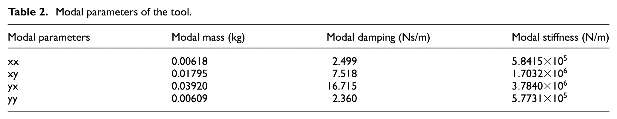
Due to w = 2πfn, the modal mass and modal damping can be computed by
Modal parameters of the tool.
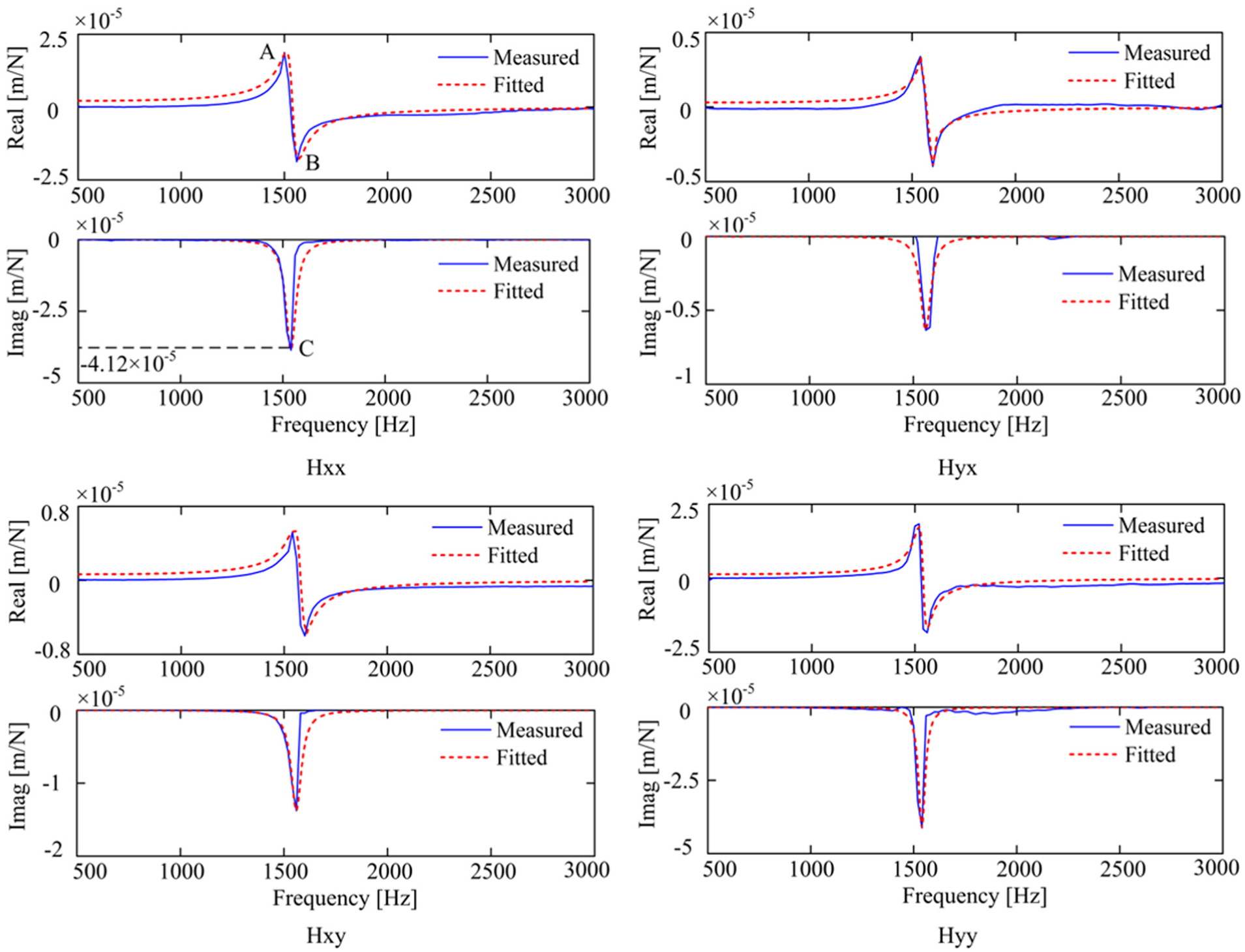
Modal fitting results of Hxx, Hyx, Hxy, and Hyy.
Stability verification
For the stability verification, this section first predicts the stability with up-milling cut for a rigid titanium alloy block. The radial cutting depth is ae = 0.25 mm and the corresponding radial immersion ratio is aD = 0.025. According to the identified modal parameters and cutting force coefficients, the predicted SLD based on the extended dynamic model is calculated by the proposed method with m = 80, as shown in Figure 8. Note that unstable regions are shaded while stable regions are left unshaded.
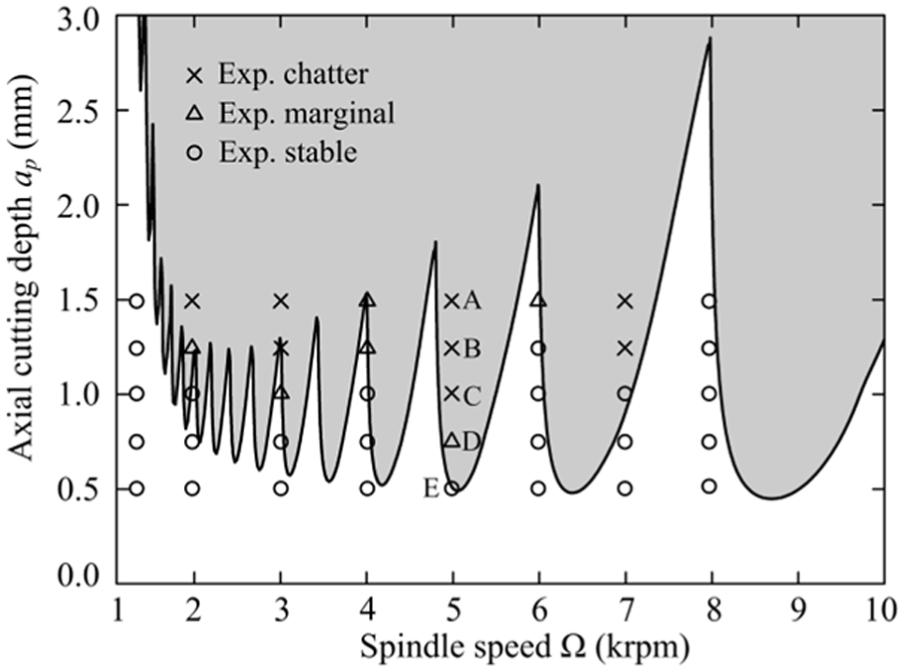
Experimental results and predicted SLD based on the extended dynamic model.
For the sake of verifying the stability prediction, a series of stability experiments at constant feed rate of 0.1 mm/tooth are performed with different parameter combinations of spindle speed and axial cutting depth. The axial cutting depth increases gradually from 0.5 to 1.5 mm in increments of 0.25 mm, and the spindle speed varies from 1200 to 8000 r/min. Once again with Kistler 9257B dynamometer, the dynamic cutting force can be measured during the milling process. Based on the machined surface quality and the FFT of measured cutting forces, the experimental stability results are obtained as depicted in Figure 8. The crosses, triangles, and circles stand for chatter, marginal cut, and stable cut, separately. As can be observed, in spite of some small quantitative discrepancies, it should be emphasized that experimental results reach a satisfying correlation with the prediction. The slight discrepancies may be due to the neglect of run-out, which could be a subject for future research.
Besides, in order to make the analysis more targeted and representative, five typical parameter combinations of spindle speed and axial cutting depth, namely, A (5000 r/min, 1.5 mm), B (5000 r/min, 1.25 mm), C (5000 r/min, 1.0 mm), D (5000 r/min, 0.75 mm), and E (5000 r/min, 0.5 mm), are selected so as to illustrate the presence of chatter and stable cuts. Figure 9 shows the experimental system of stability experiment. The corresponding frequency spectrum of measured cutting forces and the machined surface quality is as shown in Figure 10. In the case of stable point E, the measured cutting forces are mainly dominated by the tooth passing frequency
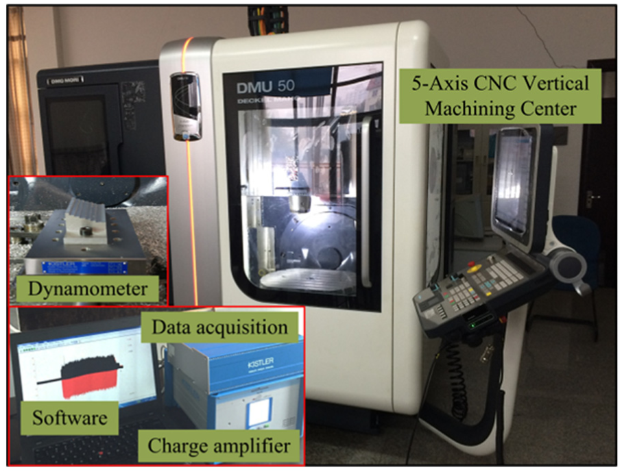
Experimental system of stability experiment.
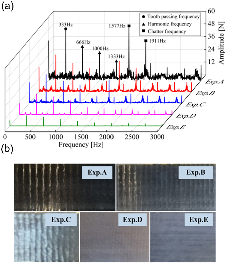
(a) Frequency spectrum of measured cutting forces and (b) the machined surface quality.
After experimental stability verification, the effects of mode coupling and process damping are further studied. Figure 11 shows the predicted SLDs based on three different dynamic models which correspond to the solid line, dashed line, and dotted line. The radial immersion ratio is kept as aD = 0.025. Solid line means the extended dynamic model with mode coupling and process damping. Dashed line represents the dynamic model with mode coupling and without process damping. Dotted line denotes traditional dynamic model without mode coupling and process damping. Through the comparison of the dashed line and dotted line, we observe that the stability regions are increased within the whole spindle speeds range due to the mode coupling effect. The reason for this phenomenon may be that the transferred energy is scattered due to mode coupling effect, although the major energy still focuses on regeneration effect. Thus, regeneration needs more energy to yield chatter and the critical stability limit increases correspondingly. Another discovery is that the critical stability limit of the solid line SLD has an obvious trend of enhancement at low spindle speeds. In contrast, the critical stability limit of dashed line SLD is always kept as constant. Additionally, the SLDs with and without process damping are basically consistent at high spindle speeds. This phenomenon indicates that process damping plays a vital role in stability improvement mainly at low spindle speeds.

The predicted SLDs with different dynamic models.
SLE verification
For SLE verification, both experimental and theoretical values need to be determined. In view of high spindle speed sensitivity, a series of cutting experiments are performed during the spindle speed range 7300–8000 r/min in increments of 100 r/min, and the axial cutting depth is chosen as a constant value of ap = 0.75 mm. The other milling condition is identical with the one in stability verification. The schematic diagram of SLE experiments is shown in Figure 12, where the original thickness of workpiece is L = 20 mm and theoretical radial cutting depth is ae = 0.25 mm. After cutting experiment, 10 measured points with equal space are selected along the machined surface at the position of half axial cutting depth. The coordinate values y of all measured points are measured by a coordinate measuring machine (Zeiss Prismo), which are depicted in Figure 13. Then, the experimental SLE can be calculated as follows
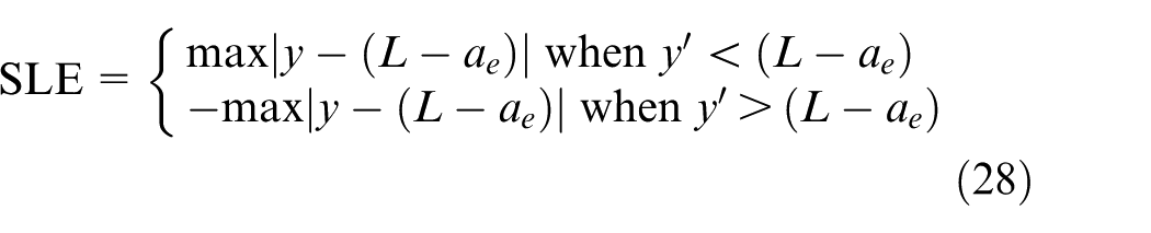
where y′ denotes the y satisfying max
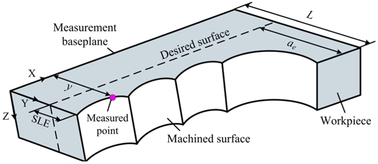
The schematic diagram of SLE experiments.
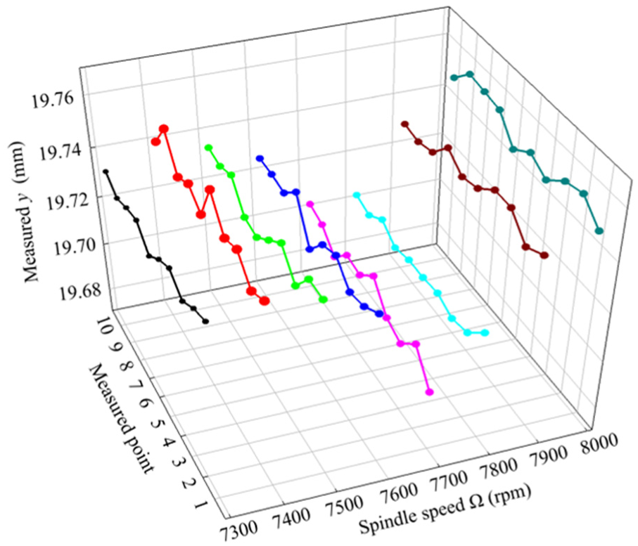
The measured coordinate values y of all measured points.
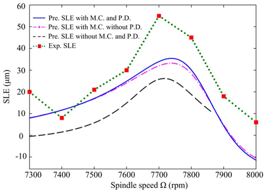
The experimental SLE is shown in Figure 14. Also shown in this figure are the predicted SLEs based on three different dynamic models which correspond to the solid line, dash-dot line, and dashed line. One should notice that the dashed line only shows the stable area during the spindle speed range 7300–7873 r/min, according to Figure 11, while for solid line and dash–dot line, stable condition can be satisfied over the whole experimental spindle speeds. Through the comparison, the solid line, which represents the predicted SLE based on the extended dynamic model with mode coupling and process damping, correlates better with the experimental SLE. This phenomenon indicates that the proposed method for SLE prediction based on the extended dynamic model can also reach a high accuracy. The possible reason for slight deviation may be tool run-out, geometric errors in the machine axis, and thermal errors. Additionally, an interesting phenomenon can be seen that the SLE is large and changes rapidly near 1550 × 60/4/3 = 7750 r/min. This is because the system resonance is excited when the tooth passing frequency and its harmonics are near the natural frequency about 1550 Hz, which results in the high sensitivity of SLE. Moreover, for up-milling, the positive SLE yields an overcut surface, while negative SLE is opposite. In actual milling process, overcut is more undesirable than undercut. Because in the case of undercut, the surface quality of the workpiece can be improved by additional material removal operations; however, in the case of overcut, the error is irreversible. Thus, a positive SLE should be avoided when selecting suitable spindle speed and axial cutting depth in up-milling.
The comparison of the predicted and experimental SLE.
Conclusion
In this article, the SLD and SLE based on the extended dynamic milling model with mode coupling and process damping are predicted simultaneously by a second-order SDM. Experimental results verify the veracity of predictions based on the extended dynamic milling model. The following conclusions are drawn from this work:
Based on traditional 2-DOF dynamic milling process with regeneration, an extended dynamic model including mode coupling and process damping is established as DDE, with time-varying coefficients. Through transformation, the extended dynamic model in the state-space form is obtained.
A second-order SDM is proposed to solve the extended dynamic model in the state-space form. The SLD and SLE can be obtained simultaneously via Floquet theory and fixed point theory, respectively. Through the comparison with the first-order SDM and the second-order FDM, the proposed method shows a faster rate of convergence.
The cutting force coefficients and modal parameters are experimentally determined. The SLD and SLE based on the extended dynamic model are predicted by the proposed second-order SDM. Via experimental verification, the experimental results are in good correlation with the predictions. This phenomenon indicates that the SLD and SLE prediction based on the extended dynamic model can achieve higher prediction accuracy compared with traditional dynamic model.
The direct and cross FRFs are measured by modal impact experiment. The magnitudes of cross FRFs are smaller than that of the direct FRFs, which demonstrates that the mode coupling indeed exists in the practical milling. Through experiments and simulation, it is shown that mode coupling seems to increase the whole stability region. As for process damping, it mainly plays a role at low spindle speeds and affects little at high spindle speeds.
Footnotes
Appendix 1
Declaration of conflicting interests
The author(s) declared no potential conflicts of interest with respect to the research, authorship, and/or publication of this article.
Funding
The author(s) disclosed receipt of the following financial support for the research, authorship, and/or publication of this article: This research is supported by the NSFC (Grant Nos. 51525501, 11290143, and 51621064) and STBD (2016RD08).