
Abstract
Incremental sheet forming is an emerging manufacturing technique in which sheet metal is formed into desired shape through the application of localized force using a hemispherical tool. Potential advantages of the process are its relatively low cost and small lead times, and these have to be balanced against the disadvantages of low dimensional accuracy and a limited understanding of the process’ internal mechanics. Incremental sheet forming system can be classified as positive, or negative, depending on whether the sheet material is progressively deformed onto a protrusion or a cavity. In negative systems, the work piece is held on a static fixture; whereas, in positive incremental sheet forming, the fixture must be incrementally lowered onto a protruding die. Although the vertical movement of positive incremental sheet forming fixtures is easily illustrated schematically, its implementation is challenging; if the descent is actuated, the motion has to be carefully coordinated with those of the forming tool; if free sliding on vertical columns, the rig must move without jamming or rocking. This article reports the development and testing of a positive incremental sheet forming fixture design that uses nylon sleeve bushes. Symmetric and asymmetric components were formed using the designed fixture, modular wooden dies and a rotating tool with multiple diameters and the results are discussed.
Introduction
Incremental sheet forming (ISF) is a family of processes where the movement of a spherical tool causes highly localized deformation of material in the surrounding area. 1 Typically, a multi-axis computer numerical control (CNC) machine with a hemispherical tipped tool and sheet clamper is used for ISF. 2 Although frequently referred to as being a die-less process, 3 such configurations are the exception rather than the rule. 4 More generally, dies are used, and ISF process can be categorized by the convexity of tooling used (Figure 1). 5 In contrast to other sheet forming processes (e.g. spinning and shear forming), ISF can create both symmetric and asymmetric shapes. 6 ISF is not limited to one-offs, but can also be regarded as a low-volume production method, 7 whose productivity and cycle time are affected by the size of the forming tool, 8 the geometry of the part being formed 9 and the type of surface finish that is desired. 10
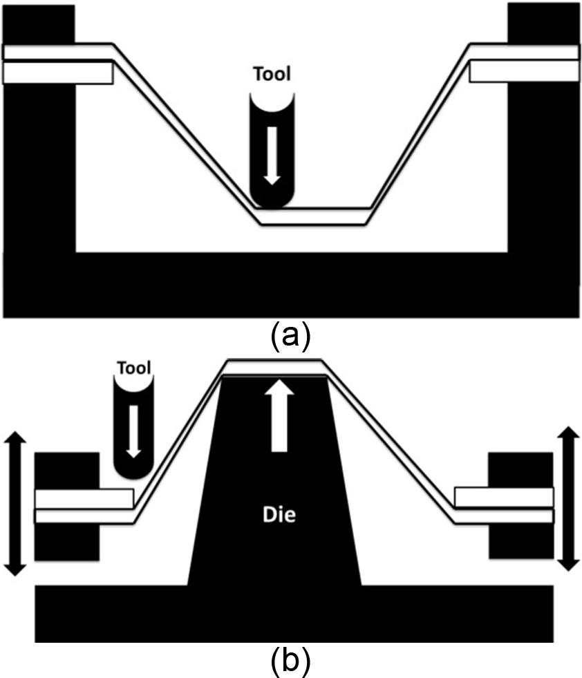
Types of incremental sheet forming fixtures: (a) positive and (b) negative.
Frequently, ISF capability is determined by the size of the fixture that can be mounted on the worktable of the CNC milling machine (the most common arrangement). 11 The fixture is usually composed of a base plate and a top plate, which holds the sheet clamped round the edges by a series of threaded fasteners. 12 Forming is caused by the pressure created by the forming tool as it follows a path generated by computer-aided manufacturing (CAM) software 13 that generates localized stresses that cause the material to yield and deform. 6 ISF process evolution and validation are discussed in greater detail in next section of the article.
In positive ISF processes, the sheet is progressively deflected onto a protrusion, whereas in negative ISF processes, the sheet moves into a cavity. In both cases, the design of the fixture is important in determining the success of the process. However, the fixture used for positive ISF must combine vertical movement with sufficient stiffness to ensure the twisting moments caused by forming operations do not cause significant deflections.
This article details the process of designing and assessing a fixture for positive ISF that uses nylon bushes to create a sheet-mounting frame that is free to move vertically while resisting horizontal twisting. A series of component parts, produced on the prototype fixture, are used to assess if the structure’s deflections impact on the geometry of the formed components.
The rest of the article has the following structure: section “Literature” briefly reviews the literature with particular emphasis on the design of fixtures, section “Fixture design methodology” outlines the design methodology while section “Detailed design and validation” validates the results and section “Discussion and conclusion” discusses the limitations of the work and draws some conclusion.
Literature
The emergence and evolution of the modern ISF process can be summarized as occurring in three distinct stages: 14
Stage 1: Emergence. The historical origins of modern ISF systems progress from the automation of artisan “panel beating” processes to CNC system over a period between 1700 and 1996. During this period, several companies were involved in developing various single-point sheet forming technologies. Initially, the focus was on variations of spinning processes (see Berghahn and George 15 and Leszak, 16 1967 patents); however, in 1978, Mason published a paper which is widely regarded as the origin of the modern ISF process. Mason analyzed different forming processes and identified the processes which are most suitable for low-volume batches. He also clearly describes the fundamentals of the ISF process in which a tool follows the contours of the geometry in three-dimensional (3D) space. 17 The large contribution of Japanese researchers to ISF started with the work of Iseki et al. 18 during 1989 when (aware of Mason’s work) he developed a sheet manufacturing system using a contour following tool.
Stage 2: Fundamentals. Most of the early research into the fundamental engineering science of the ISF process was done by Japanese automotive companies who filed several significant patents between 1993 and 2000. For example, Matsubara 19 patented both two-point incremental forming in 1994 and an extension describing the downward movement of an inclined blank in 1997.
Stage 3: Development. From 2000 onward, interest and knowledge of the ISF process spread beyond the Japanese automotive industry. Motivated by the simplicity of the ISF process, researchers in Europe and American started reporting significant work in areas such as wall angles, 20 feed rates, 21 path optimization, 22 process simulation, 23 microstructure, 24 springback, 25 accuracy, 26 applications27,28 and equipment design. Interest from the aerospace industry resulted in several well-funded research programs, and in 2003, Hagan and Jeswiet 1 published a comprehensive review of ISF technology. Since 2000, researchers have reported using an increasing range of different methods and technologies for ISF process.9,29–34
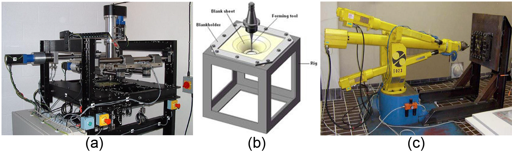
However, despite significant academic work compared to other sheet forming technologies (e.g. spinning and shear forming), the study of ISF process is at a much earlier stage and the process’ behavior still needs accurate mathematical models for different conditions and specific materials to be developed. 35 There are several different aspects of ISF technology being researched by different groups around the world. One of these research areas is the design of equipment to perform ISF processes. Broadly speaking, ISF processes can be classified as one of the following: bespoke purpose-built machines, adapted CNC machine tools and adapted robots (Figure 2). The following sections describe each of these categories.
Purpose-built ISF machines
Several groups have created dedicated ISF machines. For example, Powell created a machine to support experimental work on titanium sheet. 38 Similarly, Allwood et al. 35 reported the design of a machine, at Cambridge University, specifically for ISF process research (Figure 2(a)) that incorporates load cells to acquire forming force data as the tool moved in X, Y and Z axes. Matsubara19,39 further contributed to bespoke ISF equipment with several patents which described fixtures for single-point ISF that incorporates guiding and supporting bars for used with CNC machines. The vertical movement in Matsubara’s fixture was actuated with two servo motors. Kitazawa 40 reported work carried out on a rotating blank using a CNC machine. Motivated by the needs of automotive manufacturers, Amino et al. 3 company developed a commercial system for ISF. Another specialist machine for the ISF process was built for University of Saarbrucken by a Japanese company.41,42
Adapting CNC milling machines for ISF
However, dedicated machines are the exception rather than the rule, and most research on ISF has been performed using conventional CNC machines36,43–46 adapted with suitable tools and fixtures (Figure 2(b)). 36 Use of CNC machines is an attractive approach because of their availability and low cost (compared to other methods). A good example of this approach is the system reported by Thibaud et al. that consists of a fixed die support, a modular die, a sheet holder and attachment screws. The ISF tool is mounted on the CNC machine, and a 4-axis dynamometer is used to find forces and torque during the process. 47 Similar equipment has been used by both Ambrogio et al. 48 and Duflou et al. 49 Although the vertical movement of positive ISF fixtures is easily illustrated schematically, its implementation is challenging because of the need to create a structure that is both rigid (i.e. does not tilt horizontally) and compliant (i.e. free to move vertically as the sheet deforms).
Robot-based ISF systems
Rather than moving a forming tool with a CNC machine, other researchers have used multi-axis robots to generate forces and paths. Meier et al., for example, report the use of industrial robots, shown in Figure 2(c), to form rectangular sheets into standard geometries (cones, hemispherical and pyramids). The system supported the forming 200 mm × 200 mm sheets (with a thickness between 0.5 and 1 mm). The machine consists of fix clamper, a forming tool and a supporting tool. Both tools are mounted on industrial robots, which move through a programmed series of movements. 37 KU Leuven and IWU Fraunhofer Institute of Machine Tools and Forming Technology 50 designed and manufactured a vertical table with clamping system for use in robot-based ISF process. A coolant supply was integrated with a 6-axis robot that was used to perform an ISF process (a similar arrangement is described by Callegari et al. 51 ). A summary of the ISF systems reported in the literature is shown in Table 1.
Reported ISF machines.
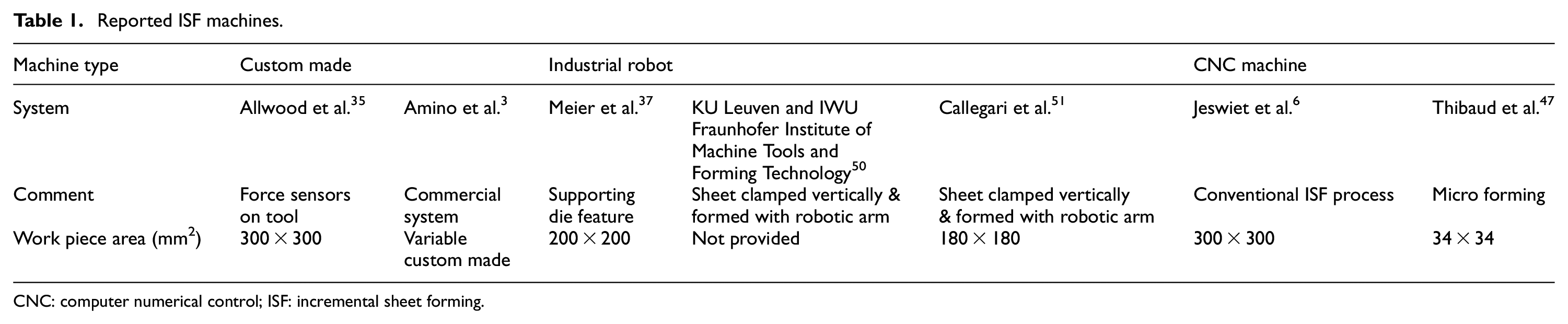
CNC: computer numerical control; ISF: incremental sheet forming.
Sheet material
The experiments used to validate the fixture design reported later this article use both plastic and metal sheet to verify different aspects of the rig kinematics and mechanical properties. A fundamental aspect of this approach to the design’s functional validation was to understand the parameters of these materials behavior in the context of an ISF process. This was done by review of the literature.
For example, Le et al. 52 discuss the relationship between tool, step size, feed rate, spindle speed and formability of thermoplastic sheets. Different polymers were studied and their appropriateness for the ISF process was established by considering springback, ductility, cost and aesthetics. High formability of plastic sheet was achieved through cold forming (ISF). Yonan et al. 53 discussed plastic flow and failure in single-point incremental forming (SPIF) for conical- and pyramidal-shaped parts. Linear strain loading paths were applied to empirically demonstrate an analytical framework’s conditions. Martins et al. analyzed several polymers for ISF process and established that certain polymers have particular material properties that make them suitable for ISF. For instance, polyethylene terephthalate exhibits high formability, similarly polyamide can also attain high formability if twisting is prevented. Polycarbonate (PC) keeps its transparency after deformation and polyvinyl chloride displays minimum springback. 54 However, wrinkles appeared in all the parts formed from plastic sheet regardless of the composition. The literature confirmed that it was feasible to use a heated polymer sheet to test the fixture’s kinematics (i.e. vertical movement) in the absence of unbalanced forming loads (see section “Detailed design and validation”).
A much large literature exists on the ISF of different metals. For example, Meelis et al. conducted a study to quantify the forces involved in an ISF process that used aluminum. He also concluded that there are accuracy problems in ductile materials such as steel and aluminum due to springback. 55 Ham and Jeswiet 56 also discussed the accuracy of the ISF process for aluminum. Robert et al. 11 discussed the manufacturing of large components with steel using an ISF process and discussed it with respect to kinematics of the tool. He used wide but shallow geometries with low wall angles to perform his study taking around 2 h to make each part. He concluded that the parts had greatest springback at the center, and similar results were reported by Muftooh et al. 57 Researchers also performed a study on the influence of forming strategy on the main strains, 58 thickness reduction59,60 and strain hardening 61 during ISF process for sheet metal. He used a spiral contour and stepped tool paths to conduct his study and concluded that spiral path is the optimum one. 58 Because the creation of the ISF fixture is motivated by an ongoing investigation in the ISF of titanium sheet, the literature provides the basic design parameters of loads and deflections (see section “Fixture design methodology”) and also provides insight into the details of the experimental validation (e.g. a spiral tool path was used to check the response to unbalanced loads). Similarly, Petek et al. 62 performed a force analysis while using ISF to form steel sheets, and so this value was adopted (with an additional factor of safety) for the fixture’s specification.
Fixture design methodology
The authors adopted Pugh’s 63 methodology for engineering design that describes a systematic process which progresses through stages of requirements generations, specification, concept generation, concept selections, prototyping, testing, detail design and assessment. Subsequent sections briefly describe each of these stages.
The requirement for an ISF fixture arose from an ongoing project to develop ISF processes for titanium sheet on CNC machines. The breadth of the investigation meant that the fixture had to be capable of supporting both positive and negative ISF operations while being sufficiently rigid to ensure the deflecting forces remained vertical.
Fixture requirements: deformation forces and forming depth
The crucial parameter in the design of an ISF system (i.e. sheet fixture and tool) is the magnitude of localized force applied to the sheet. Part of this force is transferred to the structure of the equipment while rest is used to deform the sheet itself. A study of force developed during the ISF of a steel DC05 sheet by Petek et al. 62 reported that the maximum force was just under 2 kN. Because the objective is a fixture to support the investigation of ISF processes for titanium and aluminum sheets, the design must support load and forming depth typically needed to deform the material. These are estimated as a force of 5 kN, which if applied through a 16.5-mm-diameter tool will create a pressure of 333 MPa. Pressure on tool and sheet will increase if the tool tip has a smaller diameter.
Forming depth is also an important design parameter for an ISF fixture. It was observed by the authors through initial experiments and the literature review that maximum forming depth attained for geometries (of this particular sheet size) are around 27 mm for cold-forming titanium sheet using SPIF. 57 This forming depth (27 mm) could vary depending upon temperature, sheet thickness, surface finish, tool pitch and sheet size.
Given the above, it was concluded that the design specification for an ISF fixture was that it had to accommodate maximum deformation of 100 mm in vertical direction, enable the forming of sheets with a 110 mm × 110 mm cross-sectional area and have a useable area of around 70 mm × 70 mm. Ideally, this area should be able to increase to 300 mm × 300 mm with useable area up to 250 mm × 250 mm by scaling up size of the fixture. On the bases of these parameters, five conceptual designs were generated and analyzed.
Fixture design concepts
The following concepts for a fixture to support ISF were generated and numbered as follows:
Springs: four thin pillars with tension springs pulling sheet holder down.
Servo: servo motor controlling vertical movement on ball screws.
4 pillars: four pillars serving as guide rails and fixture free to move vertically.
Scissors: scissors design takes sheet holder down with pin in the middle.
3 pillars: three pillars serving as guide rails for vertical movement.
Table 2 shows design selection matrix for all the concepts considered and the criteria used to assess their relative strength.
Concept selection matrix.
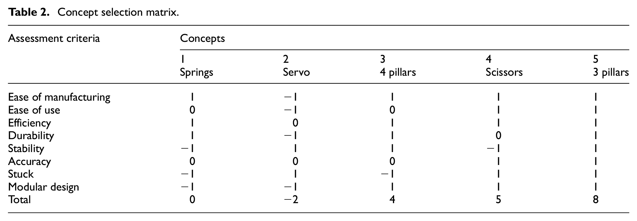
As a result of qualitative ranking in the design matrix, two concepts (4 and 5) were chosen for quantitative analysis. 3D computer-aided design (CAD) models were created for each of the three concepts. After part modeling, all the components were assembled using so-called dynamic features that defined kinematic properties of an assembly (e.g. pin joints and sliders) associated with the CAD package Creo. This enabled authors to visualize strengths and weaknesses of various concepts while analyzing their movement. Several changes to the original concept were made during modeling as assembly problems became apparent. Scissors and 3 pillars concepts are shown in Figure 3.
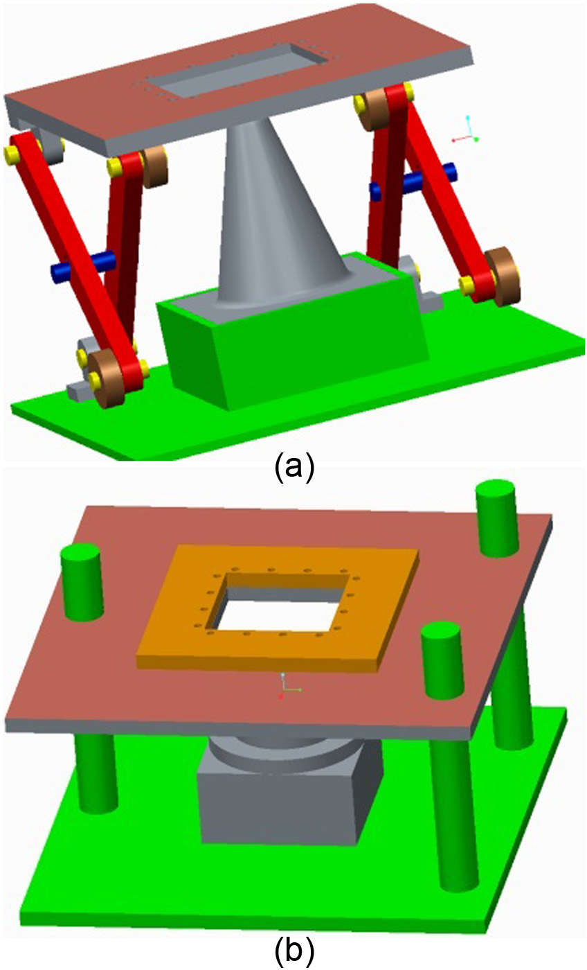
3D CAD of fixture concepts: (a) concept 4: Scissors and (b) concept 5: 3 pillars.
Prototype assessment
Concept 4 was prototyped to check the stability of the design for ISF process. Mojo® 3D printers were used to make joints between base/holder and links. Prototype was made at full scale as shown in Figure 4. Four rollers move along a straight path and let the sheet holder change its vertical position while keeping its horizontal position constant.
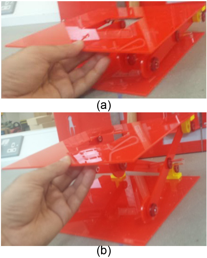
Scissors concept prototype at different levels: (a) lowest and (b) highest.
Inspection of the concept 4 prototype suggested that there were issues with its lateral stiffness. Although several modifications to the initial design were made, these changes only reduced, rather than eliminated, the lateral movement, or play, in the fixture. These trails concluded that concept 4 had inherently lower stiffness in the lateral direction, thus it was decided that concept 5 would be developed further.
Detailed design and validation
After detailed design, a functional prototype of the ISF fixture based on concept 5 was created. Steel and wooden dies with different forms were manufactured to check the kinematic and mechanical behavior of the concept 5 prototype. These dies (Figure 6(c)) are modular and can be replaced easily for forming symmetric and asymmetric shapes. 14 The steel die used to form the polymer sheet is 93.3-mm high with diameter of 10.99 mm at the top and 38.84 mm at the bottom. The wooden die used to form the aluminum sheet is 25-mm high with diameter of 11.46 mm at the top and 37.07 mm at the bottom (Figure 5). Indeed, 3D-printed polymer dies could also be used with the fixture. Nylon bushes (rather than linear rolling-element bearing) were used to enable free movement of fixture on the three columns. These bushes were selected because they have high stiffness coupled with low friction rate.
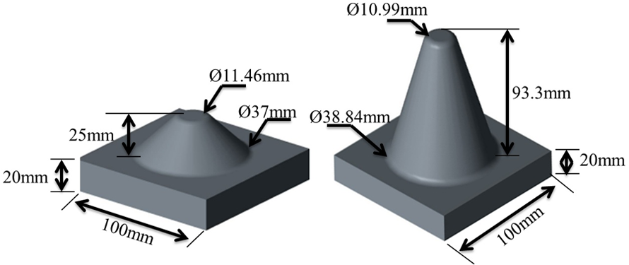
Wooden and steel dies used for forming the parts.
There are different types of materials used to manufacture polymer bushes including Teflon, nylon, phenolics and Delrin. Due to current load and environmental conditions, nylon was selected for bush material. Nylon is self-lubricating, resistant to abrasion and has a low wear rate. Several polymers absorb water from atmosphere and thus are hygroscopic. 64 With relative humidity of 40%–65%, that is, at normal environmental conditions, moisture content in nylon will hover around 1.5%–2% by weight, and consequently, the possibility of expansion has to be considered. 65 Typically, the increase in size can equal 0.5%–0.6% in an unfilled nylon 6/6 at room temperature.65–68 However, many processors will purposely condition their nylon parts as they are being molded to shorten the time frame required for the part to reach equilibrium from weeks, or even months, to a couple of days. Because of which polymers have very low capacity to absorb further moisture at room temperatures. 66
Given the compliment nature of nylon 6/6, 69 the environment of the machine shop and the fact that similar bushes have been employed successfully in analogous machine designs,70–73 any effects of moisture on the nylon bush bearings were judged to be negligible.
Kinematic assessment
The fixture was initially tested on a hard polymer (acrylic) sheet to check its vertical kinematics. The polymer sheet was placed between the upper and lower holders and secured with nuts and bolts as shown in Figure 6(a). A hand-held heater was used to simulate the vertical movement associated with the ISF process in the absence of an unbalanced force. The heater was revolved around the cone of the die to simulate ISF tool path. Heated air flow directed at a localized area increased the temperature of the polymer sheet to 148.8 °C. This increase in temperature and the fixture weight forced the sheet to deform into shape of die. Figure 6(a) shows the initial position of the sheet when sheet started deforming, and Figure 6(b) shows final deformed part. This test validated the ability of fixture to move vertically and was considered successful since no jamming or rocking effects were observed. Although this experiment was successful, it did not include any lateral forces and did not check for stiffness and torsional resistance of the structure subjected to the loads required for an ISF process. To check fixture for these conditions, further tests were performed on aluminum sheet using rotary tool.
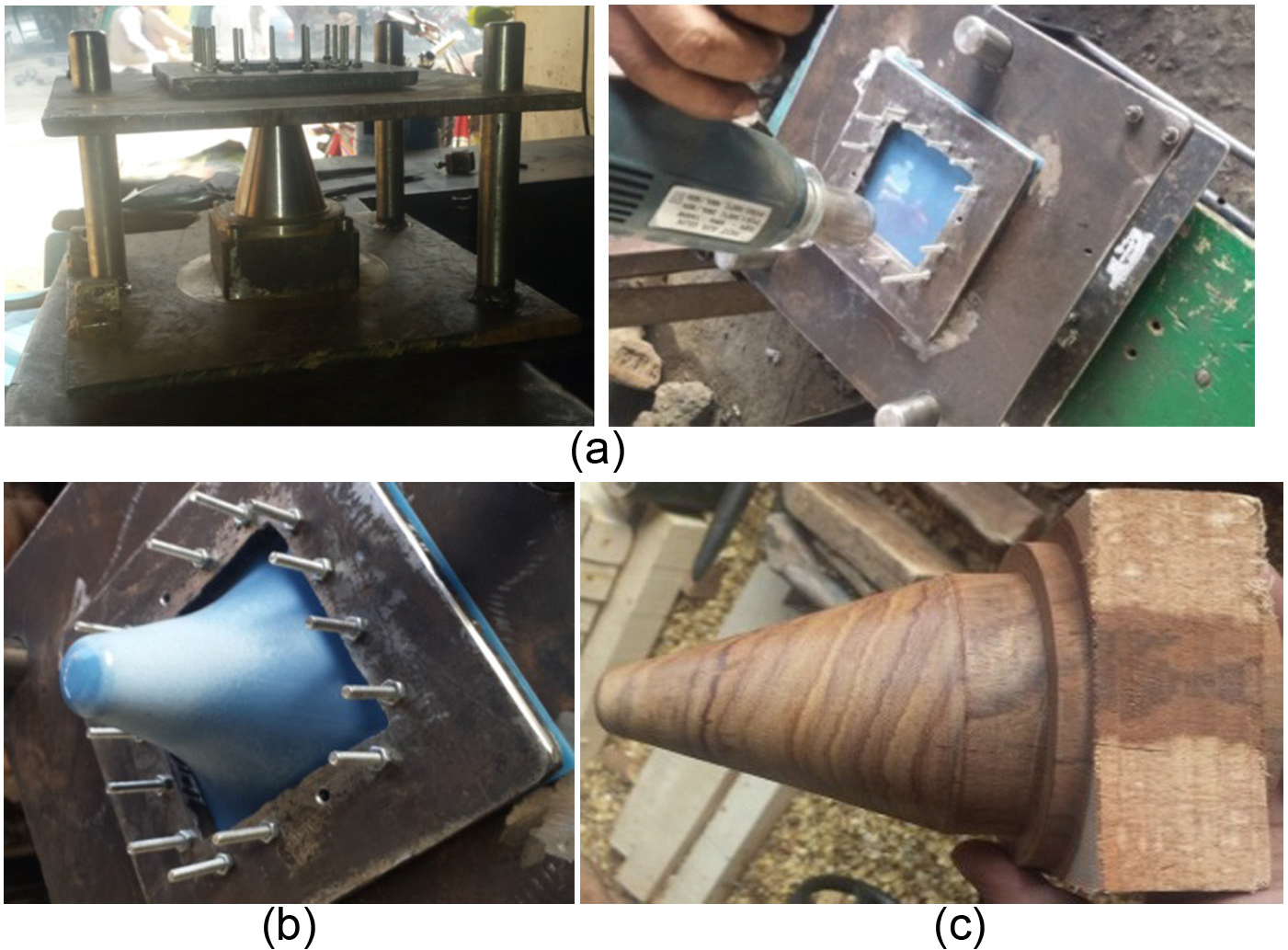
Testing on polymer sheet: (a) start, (b) finish and (c) wooden die.
Mechanical assessment
Several tests using metallic sheets were performed using the flexible fixture to check its stability, alignment, stiffness, torsional resistance and freedom of movement. The rotating tool and a wooden die were used to perform these experiments. The rotational speed of the tool depends upon the relative velocity between the tool and the metal sheet. Thrust bearings are used to align and hold the tool stick while it is rotating (Figure 7(a)). Rotation is helpful in reducing friction between the metal sheet and the tool. Sheets were formed until the point of fracture (maximum depth) to check the behavior of fixture under extreme operating conditions. This was done because all three components of force increase in magnitude with the forming depth, and the force applied to the sheet and the fixture reaches a maximum just before fracture. Three of these tests are reported in this study. The fixture and tool were mounted on a 3-axis CNC milling machine as shown in Figure 7, and an ISF process was carried out an on an aluminum sheet (AA 1050). Material properties acquired through tensile tests of aluminum sheets used in testing fixture are given in Table 3.
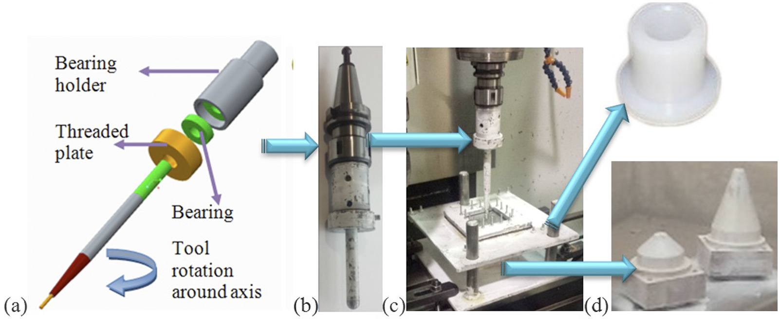
ISF equipment: (a) CAD model of rotating tool (4.5 mm in diameter), (b) rotating tool (16.5 mm in diameter), (c) equipment mounted on CNC and (d) nylon bushes and wooden dies.
Material properties aluminum used in the fixture assessment.
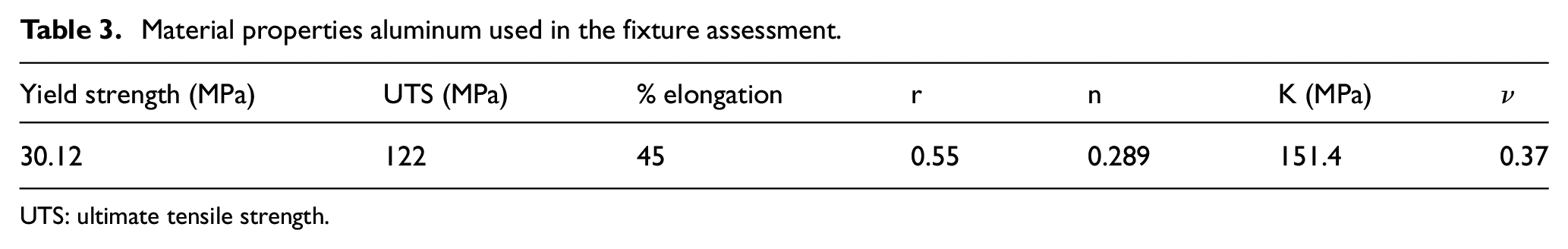
UTS: ultimate tensile strength.
Where r is a measure of plastic anisotropy, ν is Poisson’s ratio, K is stiffness and n is strain hardening coefficient. Although the total area is 130 mm × 130 mm, because of the margin used to clamp the sheet in the fixture, working area of the aluminum sheet is 70 mm × 70 mm.Figure 7 shows the fixture mounted on a CNC machine while performing the ISF process. The tool moves in a spiral path around the truncated coned to form the part. Figure 8(a) shows the output of the CNC milling simulation, where the tool starts from a smaller diameter and moves toward bigger diameter. With the help of a positive wooden die, a convex surface was produced. The value of pitch used for the test was 0.5 mm and feed rate was 1000 mm/min. A milling process simulation with tool is shown in Figure 8(c), where material is being removed from a block.
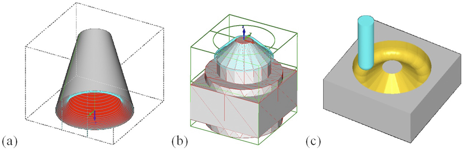
Tool path of ISF process: (a) surface of inward-out movement, (b) tool path over a die and (c) milling process simulation.
Three different tests (Cases A, B and C) were used to check the fixture’s stiffness and movement under different load conditions and forming parameters (i.e. tool size and die geometry). Cases A and C are axi-symmetric geometries, while case B is asymmetric geometry. Most of the parameters for these three cases are the same. Varying parameters are listed below and the resulting parts are shown in Figure 9.
Case A. Tool size: 4.5 mm, die at center of Al sheet.
Case B. Tool size: 16.5 mm, die off-center of Al sheet.
Case C. Tool size: 16.5 mm, die at center of Al sheet.
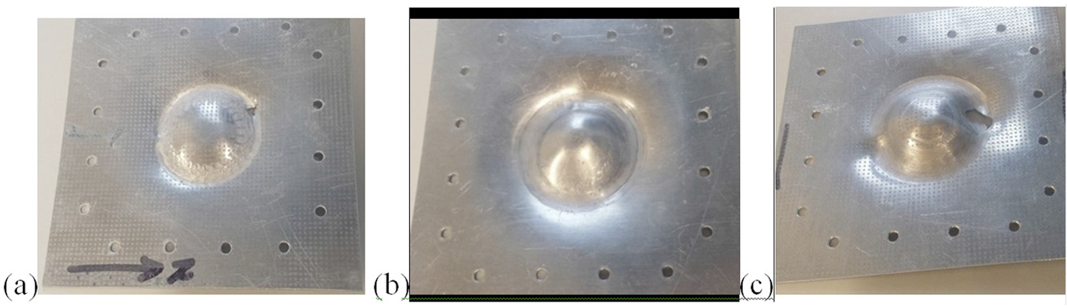
Final aluminum sheets: (a) case A, (b) case B and (c) case C.
Part thickness and profile assessment
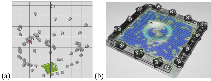
Different parameters of the ISF-manufactured geometry were measured optically using a GOM ATOS Tripple Scan III scanner as shown in Figure 10. Because aluminum is an extremely reflective material, a thin layer of paint (Ardox) was applied to eliminate any specular reflection and acquire robust and continuous data from the 3D scanner. The resulting point cloud was polygonized, smoothed and processed to get final useable data.
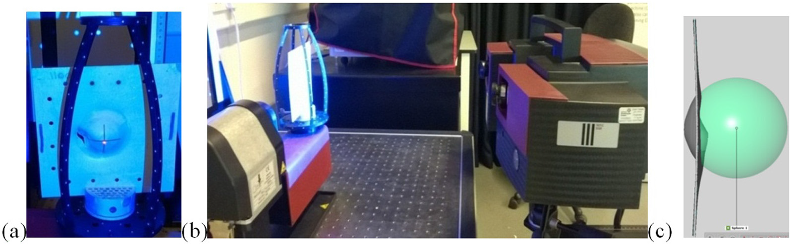
3D scanning: (a) formed part in scanning frame, (b) part being scanned and (c) scanned geometry centered.
Parts formed with aluminum sheet through ISF process were observed to have a generally good condition (i.e. shape and surface finish) as shown in Figure 11. All three results show uniform distribution of thickness in the area formed by ISF, that is, regions A and B.
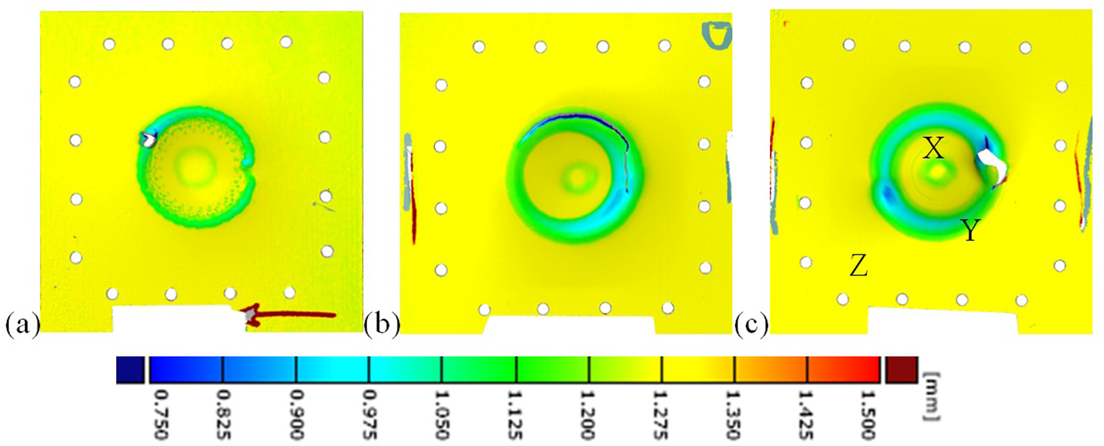
Thickness profiles of the sheet for (a) case A, (b) case B and (c) case C.
Regardless of the fact that a point load is applied on the sheet at distance from center, creating a moment and a torsion, in both sheet and the flexible fixture’s structure, and that the tests were continued up till their failing point, a significant degree of symmetry and evenness of distribution in thickness was achieved in all the test results. This confirmed the stability and rigidity of the flexible fixture while moving vertically during ISF process. Surfaces on both sides of the sheets were fairly smooth although bends can be seen near the external diameter of the formed shape. A grid of etched marks was worn off the surface, where the tool was in contact with the surface, but is visible on other side of the surface. It is observed through thickness profile analysis that all the sheets had localized thin areas (Figure 11). These thin areas were in contact with the rotating tool and wooden die. Central green circle (X) was in contact with the wooden die and material was thinned over the edges of die up to 1 mm (initial thickness of the sheet was 1.3 mm) with width of 5 mm. The external circular region Y was forced down through localized dynamic application of the force. The external circular region width varies from case to case. Cases A, B and C formed part by rotating tool, and region Y has width of 6, 8 and 15 mm with area equal to 6940, 9160 and 1021 mm2 and fracture depth of 14.2, 16.3 and 17.8, respectively. Case B has non-uniform distribution of thickness reduction due to off-centered die. Region Y is deformed through multiple passes of the tool over the sheet. Thickness is not uniform throughout this region and the minimum thickness was observed in the middle of this region for all the three cases. However magnitude of the sheet thickness varies from case to case. For case C, thickness on sides of this region is 1.25 mm and it reduces to 0.95 mm in the middle and further to 0.75 mm just before the fracture.
Region Z, that is, from sides of the sheet until region Y, should have no reduction in thickness. Although region Z has no thickness reduction, it does not have a straight profile as shown in Figure 12, and it is evident that sheet makes a small angle (less than 10°) to horizontal plane. This phenomenon occurs due to springback, and similar results have been reported previously. 57 The location of the maximum bend and minimum thickness are, surprisingly, not the same. It is observed in all three cases that crack starts along rolling direction.
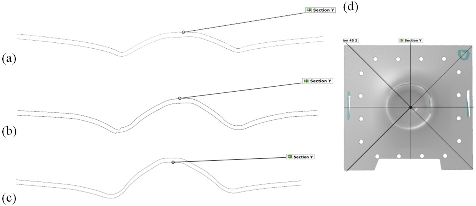
Geometric profiles of the sheet: (a) case A, (b) case B, (c) case C and (d) 3D scan of case B with section lines.
It is concluded from these three cases that both the tool path and the size of forming tool compared to geometry size influence the formability and quality of the ISF process. However, these crucial results confirmed that the fixture’s dynamics were not impacting significantly on forming process and that the nylon bushes had sufficient stiffness to support the process.
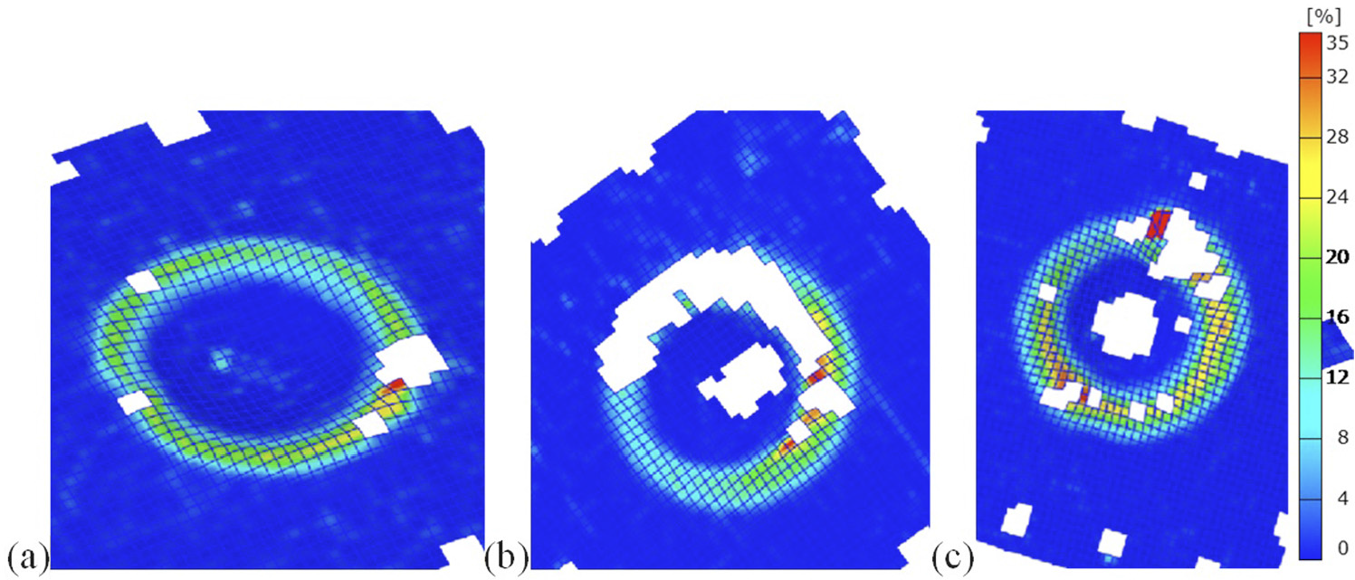
Thickness reduction percentage for all the three cases are observed in localized regions and shows that the flexible fixture has sufficient alignment, rigidity and freedom to move. The range of thickness reduction for all the cases is similar but the magnitude of percentage reduction in thickness varies at from case to case with respect to location as shown in Figure 13. For case A, region Y, the thickness reduction is between 8% and 12%. After which, rapid thinning is observed at the very last instant due to the tearing effect of the narrow tool (4.5 mm). Case B is similar to case A, but instead of thinning at a point, gradual thinning in quarter of the circular region is observed. Case C shows more uniform distribution of thinning reduction, and the sheet is thinned gradually for the whole circumference of the spiral tool path. For case C, thickness reduction around corners of the circular region is 8% and increases to 20% in the middle. A thin line with 25% thinning is observed exactly in the middle of the region, which increases to 35% while moving toward the fractured area. This change in thickness across cross-section of sheet is due to multiple passes over the sheet. Maximum thickness reduction of 35% is observed just before cracking for all the cases. Arrows show the rolling direction of the sheet. Tool should not repetitively contact sheet at the same location to avoid this thinness effect. Tool path optimization can play main role to avoid this to happen.
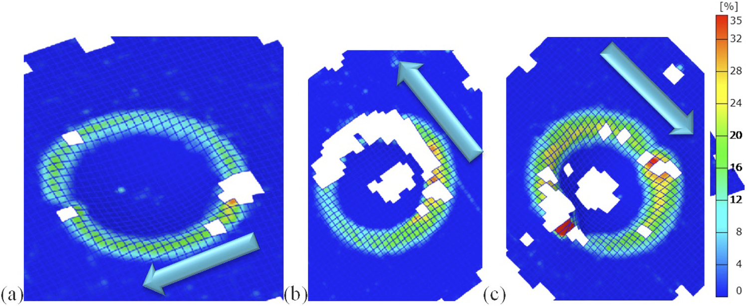
Thickness reduction % of the sheet: (a) case A, (b) case B and (c) case C (arrow shows rolling direction).
Strain assessment (major, minor and von Mises)
To further investigate the dynamic behavior of the ISF fixture, aluminum sheet was electrochemically etched, before performing ISF process, with a grid of circles of 1-mm diameter and 2-mm apart from each other. Photographs with Nikon D300 camera were taken at various locations to digitize these circles as shown in Figure 14(a). Two scales were used to identify the size of the part as shown in Figure 14(b). Major and minor strains were acquired using strain point data through circular grid analysis technique, which is widely used in sheet metal forming.20,74–77 At times, some data is lost during acquisition of result, which creates discontinuity or patches.55,76 This is because circular grid is either erased or becomes very faint due to the forming process and thus could not be recognized by the system.
(a) Location of photos and (b) formed surface through ARGUS.
Major strains are positive in all the three cases as shown in Figure 15 and confined to the localized regions X and Y, while the rest of the area was not deformed. This demonstrates rigidity of the fixture even though it was moving vertically downward while high lateral forces were being applied on the sheet to fracture the part. For case A, major strain is zero at region Z and 12% for most of the area. But as the tool is following a spiral path, it increases to 35% just before it cracks. The maximum value of cases B and C is 35%. Case C has the largest area under action due to higher tool size and centered die. For this case, last pass of the rotating tool has a higher magnitude of major strain ranging from 25% to 35% distributed along circumference.
Major strain profile in the sheets: (a) case A, (b) case B and (c) case C.
Minor strain is negative for all three cases as shown in Figure 16. The values lie in a range from 0% to −10%. All the cases show similar behavior, but case C has more clear divisions between different areas. In regions X and Y, strain clearly ranges from −6% to −10%, while rest of area is near 0%. So it can be concluded from these three figures that the more the part is formed (higher deformation) the more area will go under compression for positive die. It is evident from Figure 16 that only localized area has minor strains in negative value while it is zero across rest of the sheet, thus it can be concluded that stiffness of the fixture is sufficient to hold the sheet aligned.
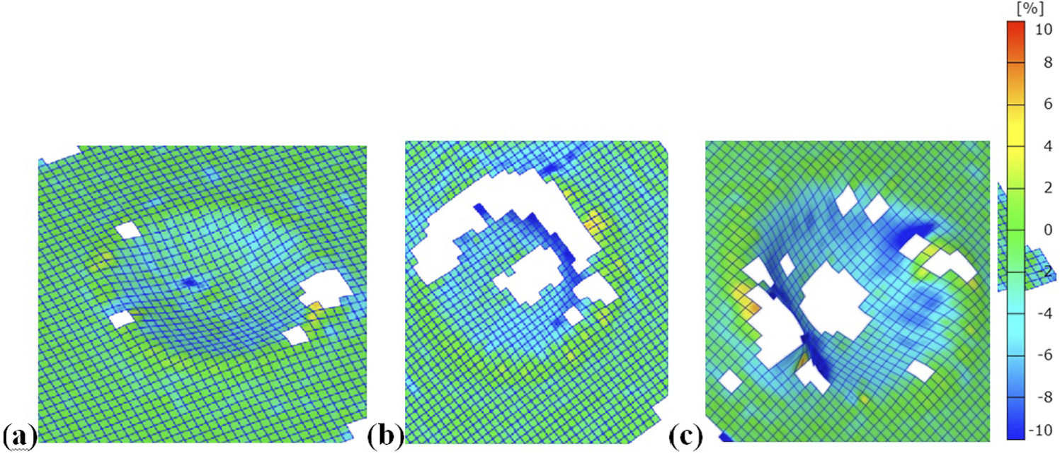
Minor strain profile in the sheets: (a) case A, (b) case B and (c) case C.
Because the minor strain has negative value in all the formed regions, it is a tension-compression case, which is known to be acting in other sheet forming processes as well. The evenness of the distribution suggests that the fixture is enabling but not distorting the ISF process.
As von Mises strains are the equivalent strains of all six components of strains (εxx, εyy, εzz, γxy, γyx and γyz), they provide a useful metric for assessing the evenness of the sheets deformation on the fixture. Strain in other regions of sheet would mean that fixture had moved while sheet was being formed. For all three cases A, B and C, strain was localized in regions specified by the tool path as shown in Figure 17. Von Mises strains in region Y vary in a range of 7%–50% for all three tests, but distribution of strains varies from case to case. For case A, that is, thinner tool size, most of the area remains between 10% and 20%. Strain moves from 20% to 30% across 90° of region and suddenly ruptures the part in a comparatively small distance and goes to 50%. This is due to more localized stress because of smaller tool size which tears the sheet apart. For case B, that is, off-center die with larger tool size, strain remains between 10% and 20% for two-thirds of the region Y. For rest of one-thirds region, it varies uniformly and increases gradually to 50%. Case C, that is, center die with bigger tool size, shows most uniformly distributed von Mises strains range between 35% and 50%. This shows that to acquire greater formability from a part, larger tool size and centered die are the best options. Different dynamics seem to be working in all three different cases due to different input effects. It is hard to establish from current results that which criteria of failure is causing rupture and what is the state of the stress in elements just before failure. Although these results point to several interesting avenues for future research, they confirm the designed equipment is correctly functioning.
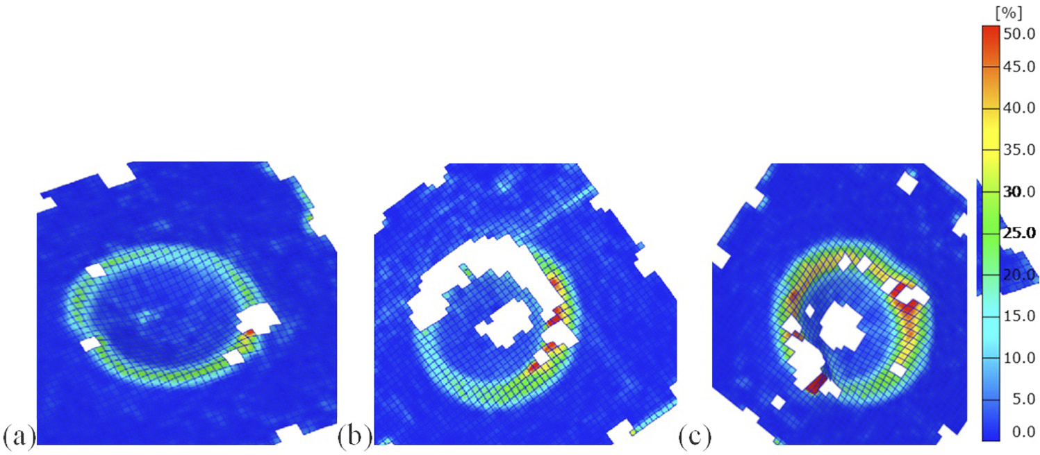
Von Mises strain profile in the sheets: (a) case A, (b) case B and (c) case C.
Discussion and conclusion
ISF is one of the most simple, effective and efficient sheet forming processes. One of the areas researchers are working on is the fixture and tool design for this process. Flexible fixture design for ISF process is a challenge because of highly localized but moving off-centered torsional load applied to form the sheet metal. This loading condition can jam the fixture and jeopardize its freedom of movement and stiffness while part is being formed. Aware of this problem, the authors created several concepts and evaluated against the design specifications of ISF Process. 3D modeling, visualization and finite element analysis and functional prototypes were assessed before manufacturing the flexible fixture with nylon bushes.
The results suggested that the Scissors design did not have sufficient lateral (i.e. horizontal) stiffness, so consequently the 3 pillars concept with nylon bushes was selected as the final design. Polymer sheet with industrial heater was used to check the functionality and the large vertical movement of the fixture during ISF process. Tests were successful and sheets were formed in shape of die. After which fixture was mounted on a CNC machine and further tests were performed on aluminum sheet to check rigidity and stiffness of the system under high loading conditions. Spiral tool path was generated with CAM software for tool movement to form the geometry. Three cases were studied to check fixture movement for different tool sizes, symmetric and asymmetric geometries. After which results such as thickness reduction, profile changes, major and minor strains and von Mises strains were acquired from these sheets using circular grid analysis, 3D scanning and other state-of-the-art methods. All the parts were formed up to their failing point, despite which significant symmetry and evenness of distribution in formed parts was achieved. Results such as strain in other regions of sheet would mean that fixture had moved unevenly while the sheet was being formed. Cheap wooden dies were successfully used to form aluminum parts. Using polymer or wooden dies would bring down cost and time of forming substantially. Other geometries were formed up to 40-mm depth using the same aluminum sheet metal.
Regardless of the fact that a point load is applied on the sheet at a distance from center, creating a mixture of bending, tensile and torsional loading both on sheet and structure the fixture remained stable, showing no signs of unwanted movement with the nylon bushes, providing sufficient stiffness.
Footnotes
Acknowledgements
The authors acknowledge AFRC, Mr Lala ZDE, Mr Dunkin, Mr Steven, Mr Barrie, Dr Dorothy Evans, Mr Umer Farooq and Miss Shahana Mujeeb for their continuous help and support.
Declaration of conflicting interests
The author(s) declared no potential conflicts of interest with respect to the research, authorship and/or publication of this article.
Funding
The author(s) received no financial support for the research, authorship and/or publication of this article.