
Abstract
Cenosphere fly ash particles as waste by-product of gas thermal power plant are successfully incorporated into AA6061 aluminium alloy by improved wettability casting process called compocasting technique to enlarge the application barrier of existing advanced metal matrix composites due to their high fabrication cost. Thereafter, microstructure, interface and composition of the prepared composites were analysed from the X-ray diffraction analysis patterns and scanning electron microscopy equipped with energy-dispersive X-ray techniques. Furthermore, machinability characteristics were identified by wire electrical discharge machining to explore the co-relations among the machining variables and the performance measures such as cutting rate, kerf width and surface roughness for the prepared composites by varying one parameter at a time and keeping the other parameters as constant. The morphological study reveals that there is a uniform distribution of fly ash particles in aluminium matrix phase without formation of any intermetallic compound caused by interfacial reaction. The machinability study indicates that pulse-on-time and pulse-off-time are the most significant process variables that affect the machining performance of the prepared composites. However, wire feed is found to impose the least significant effect among the three process parameters. Also, the neat AA6061 aluminium alloy (0% AA6061/cenosphere composites) exhibited superior machining performance compared to both the reinforced composites (4% and 8%) at similar machining conditions.
Keywords
Introduction
Nowadays, metal matrix composites (MMC) have tremendously increasing demand in thermal management areas, as well as in sports and recreation. Aluminium-based metal matrix composites (AMC) are gaining significant interest in high-tech structural and functional applications including aerospace, defence, automotive and sports equipment manufacturing industries, due to their interesting mechanical and material properties such as high strength, high stiffness, damping capacity, reduced density and improved abrasion and wear resistance capacity compared to unreinforced alloy.1–3 However, increasing demand of AMCs creates challenges to make mass production of AMCs at low fabrication cost. As a result, there has been gaining significant interest in reinforcements containing low density and low cost such as fly ash and natural minerals. Fly ash is available in large quantities as solid waste by-product during combustion of coal in thermal power plants. 4 Since fly ash has found an inexpensive resource material, composites with fly ash reinforcement are likely to overcome the cost barrier for widespread applications in automotive and small-engine applications.5,6
Currently, there are several fabrication methods used to synthesize AMCs reinforced with different kinds of ceramic particles which include, but not limited to, powder metallurgy, 7 mechanical alloying, 8 squeeze casting, 9 stir casting, 10 compocasting 11 and spray deposition. 12 The mechanical and the tribological behaviours of the AMCs are influenced by the processing method. Enhancement of AMC properties requires the successful incorporation of ceramic particles into the aluminium matrix and obtaining good bonding between them. The processing methods mentioned above may be classified as solid-state processing and liquid-state processing. Liquid-state processing is more preferable because of its simplicity, ease of adoption and applicability to mass production. 13 Stir casting liquid method is widely used as processing route to prepare AMCs where aluminium alloy is completely melted and reinforced particulates are added into the molten metal in a vortex created using a mechanical stir. 14 However, to improve the casting quality in stir casting process, different methods were attempted such as preheating the reinforcement particles to enhance the wettability; 15 additionally, introduce wettability agents 16 and fluxes 17 using coated 18 and wrapped 19 filler material which attributed better mixing between the ceramic particle and the molten alloy matrix. These accessory techniques associated with the stir casting process have increased the overall cost of fabrication. Another economic and modified stir casting method has been reported to synthesize AMCs known as compocasting process where the alloy matrix is kept in semi-solid state instead of fully molten state by controlling the casting temperature. Several researchers established that the prepared AMCs using compocasting technique have improved wettability and better distribution of ceramic particles in Al alloy matrix.20–25
However, the influence properties that are associated with the MMCs confronted a lot of challenges while machining on it. Since hardness, toughness and impact resistance of the MMCs were increasing after addition of reinforcing materials, it has become difficult to machine those composites by traditional machining processes due to the abrasive nature of the reinforced particles.26,27 However, several investigators have made effort to apply different non-conventional machining methods like abrasive water jet, laser cutting and die sinking electric discharge machine (EDM) to process the MMCs.28–31 But these processes showed certain disabilities like unable to cut linearly and required elaborate preparation of pre-shaped electrode (tool). Few researchers have reported that the wire electrical discharge machining (WEDM) process can overcome those limitations and exhibited better machining performances and economical tool in the machining of composite materials. 32 WEDM is a specialized non-conventional machining process which is mainly used for the machining of any electrical conductive materials irrespective of their material hardness and strength. It is capable of producing intricate shapes with fine finish and extremely high accuracies. The most important measures of performance in WEDM process are cutting rate or cutting speed, surface roughness and kerf width. 33 WEDM is a controlled thermal erosion machining process where electric energy is transformed into thermal energy and generates a series of electric spark for processing the electrically conductive workpiece. However, WEDM is a modification of the traditional EDM process where the tool electrode is simply a thin conductive wire. The process does not have any direct contact between the workpiece and the wire electrode, and therefore, it eliminates the mechanical stresses during machining.34–36 Very few literatures have reported on WEDM characteristics of particle-reinforced AMCs.
Prakash et al. 37 investigated the machinability of the prepared A413/fly ash/B4C Hybrid composites in WEDM and recognized that gap voltage is the most important factor affecting material removal rate (MRR). Liu et al. 38 performed machining operation on Al (6061)/Al2O3 composite using wire electrochemical discharge machining and found that high applied voltage and long pulse duration reduces the MRR. Sharma et al. 39 evaluated that large-size craters and cracks are formed on the machined surface when pulse-on-time increases and pulse-off-time is kept at lower level during machining of Al (6063)/ZrSiO4(p) MMC. Patil and Brahmankar 40 reported on WEDM characteristics of SiC particle–reinforced AMCs. The surface roughness of AMC was found to be improved than that of the unreinforced alloy, and the cutting speed of AMC was lower compared to the cutting speed of matrix alloy. In their recent studies on WEDM behaviour of Al/Al2O3p composites, cutting speed was observed to decrease with the increase in percentage of reinforcement particles. However, the quality of surface finish was observed to deteriorate with increased percentages of ceramic reinforcements. 41 Yue and Dai 42 studied the WEDM behaviour of alumina particle and short fibre–reinforced AMCs under coarse and fine cutting conditions and suggested that the surface roughness of unreinforced matrix was higher than Al2O3p-reinforced MMCs. In another study by Yue et al. 43 on WEDM of Al2O3 particulate–reinforced AMCs, it has been reported that the surface roughness did not differ significantly, but their corresponding topographies were found to be intrinsically different. In addition, bandings were observed on the wire electrical discharge (WED)-machined surfaces of some fine cut specimens and were believed to be caused by wire shifting. Gatto and Iuliano 44 performed WEDM of SiC/2009Al alloy with 15% whiskers and 10% reinforced particles under one roughing and two finishing conditions to understand the effects of reinforcement and the behaviour of the matrix during the machining. They reported that the reinforcement particle was absent in the recast layer of WEDM surface. Rozenek and Kozak 45 experimentally investigated the effect of various machining parameters on the machining feed rate and surface roughness during WEDM of AlSi7Mg/SiC and AlSi7Mg/Al2O3 MMCs. The observation reveals that pulse-on-time and peak current have significantly influenced the surface roughness and cutting speed. Yan and Tsai 46 studied extensively one-factor-at-a-time approach on WEDM of Al/Al2O3p composites and reported that the reinforcement of ceramic particles was more significant than the discharged energy on surface finish of the composites. The value of surface roughness was found to increase significantly with the increased volume fraction of the reinforcement particles. The surface finish of MMCs after WEDM was significantly different than that of unreinforced matrix alloy. Lal et al. 47 investigated the effects of WEDM parameters on the surface roughness of newly developed hybrid Al7075/Al2O3/SiC MMC. Pulse-on-time, pulse current and pulse-off-time were identified as the significant process parameters, whereas the wire drum speed had insignificant effect on the machining responses. Pramanik et al. 48 studied the nature of surface finish and dimensional accuracy during WEDM of MMCs for different reinforcement sizes and machining conditions. It has been reported that the reinforcement particle size, pulse-on-time and wire tension significantly affect the diameter error, circularity and surface roughness. Surface defect got reduced with the increase in particle reinforcement caused by resistance to melting of the surface. Amini et al. 49 optimized the WEDM parameter while machining the TiB2 nanocomposite ceramic and reported that the optimization results had a good agreement with the experimental process outputs. However, the literatures reported on non-conventional machining of cenosphere-reinforced Al MMCs and investigations on the WEDM characteristics, in particular, are scarce in general.
In this work, an attempt has been made to prepare cenosphere fly ash–reinforced Al6061 alloys using a simple and cost-effective processing route, that is, compocasting method. Fabricated composite has also been characterized through X-ray diffraction analysis (XRD), field-emission scanning electron microscopy analysis (FESEM) with energy-dispersive X-ray techniques (EDX) and analysing the morphological behaviour of the composites. Furthermore, machining was done in WEDM to investigate the effects of process parameters and weight fraction of the reinforcement on the machining responses, namely, cutting speed, kerf width and surface roughness of the prepared composites by varying one parameter at a time approach.
Materials and methods
Material selection
AA6061 aluminium alloy is considered as matrix material for fabrication of the AMCs. AA6061 is one of the most extensively used 6000 series aluminium alloys. It possesses good fracture toughness and excellent corrosion resistance property with proficient workability. The density of the AA6061 alloy is 2.7 g/cm3, and it is ductile in nature. The chemical composition of AA6061 Al alloy used in this work is given in Table 1.
Chemical composition of aluminium alloy (AA6061).

Fly ash is a solid waste by-product, and it is found in thermal power plants. Fly ash particles are classified into two types, namely, precipitator and cenosphere. Fly ash particles, which are in the form of solid spheres, are known as precipitator fly ash. The density range of precipitator particles is 2.0–2.5 g/cm3. However, hollow spherical fly ash particles are termed as cenosphere. In cenosphere, the density varies in the range of 0.4–0.7 g/cm3. The FESEM micrograph equipped with EDX and the XRD pattern of the cenosphere particles are shown in Figures 1 and 2, respectively. The EDX spectrum of fly ash in received condition shows the presence of Al, Si, O, Fe, Ti and K peaks in the fly ash which infers that all the major constituents of fly ash particles have been carried as shown in Figure 2. The XRD spectra of fly ash in received condition are shown in Figure 2, which exhibit the phases present in the fly ash, and it has been found that the major composition of cenosphere fly ash, such as SiO2, Fe2O3, Al2O3 and MgO, is distinctly seen.
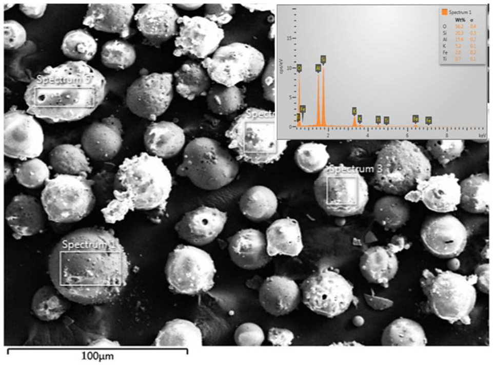
FESEM micrograph of cenosphere fly ash particles.
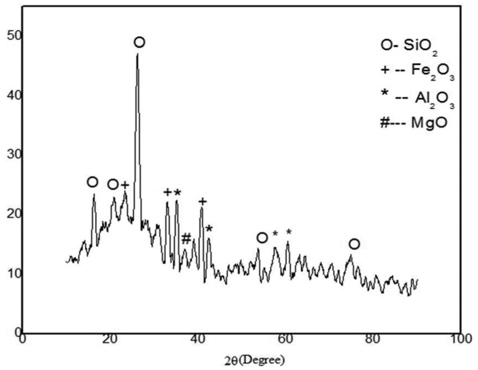
XRD pattern of cenosphere fly ash particles.
Specimen preparation
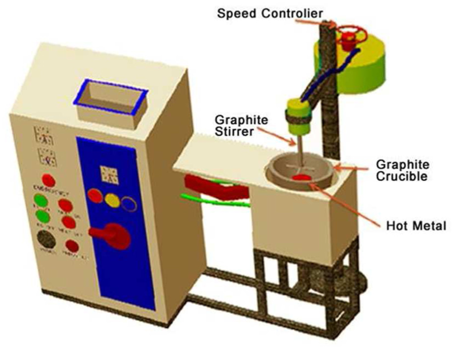
The synthesis of AA6061/fly ash composites used in this work was carried out using compocasting technique. The fabrication process was done in Megatherm Induction Furnace (Werner Finley Pvt Ltd) with a mechanical stir as shown in Figure 3.
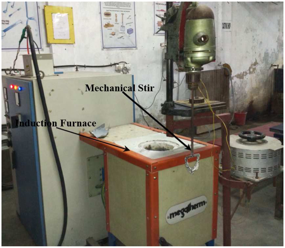
Megatherm Induction Furnace with mechanical stir.
AA6061 aluminium alloy rods were placed in a graphite crucible and heated in an induction electric furnace. The temperature of the furnace was maintained at 610 °C where Al6061 alloy reaches semi-solid state. Vortex was created by a mechanical stir at a speed 550 r/min which was driven by an electric motor. The received cenosphere particles were preheated to around 250 °C in a muffle furnace to remove the moisture before pouring into semi-solid melt inside the crucible. The iron mould was also preheated up to 650 °C in order to prevent the loss of heat of the pouring metal and to avoid the rapid solidification. The specific amount of preheated fly ash particles was then added to the vortex and concurrent stirring was continued to facilitate uniform distribution of fly ash particles in aluminium matrix phase as shown in Figure 4. The semi-solid reinforced melt was then poured into the preheated permanent iron mould and allowed to solidify at room temperature. The same processing technique was repeated for all the three prepared composites with different weight fractions of reinforcement as 0%, 4% and 8%. Figure 5 represents a schematic of compocasting setup. Composites were prepared from the compocastings to carry out microstructural characterization and subsequently processed for machinability characteristics. The processed composite samples for WEDM and their subsequent steps to measure the kerf width and surface roughness are shown in Figure 6(a)–(c).
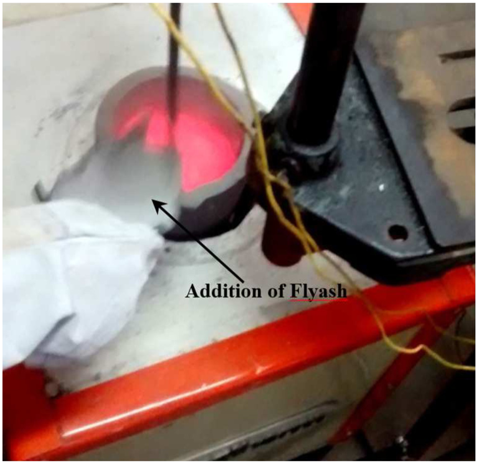
Fly ash added into the semi-solid alloy.
Schematic diagram of compocasting setup.
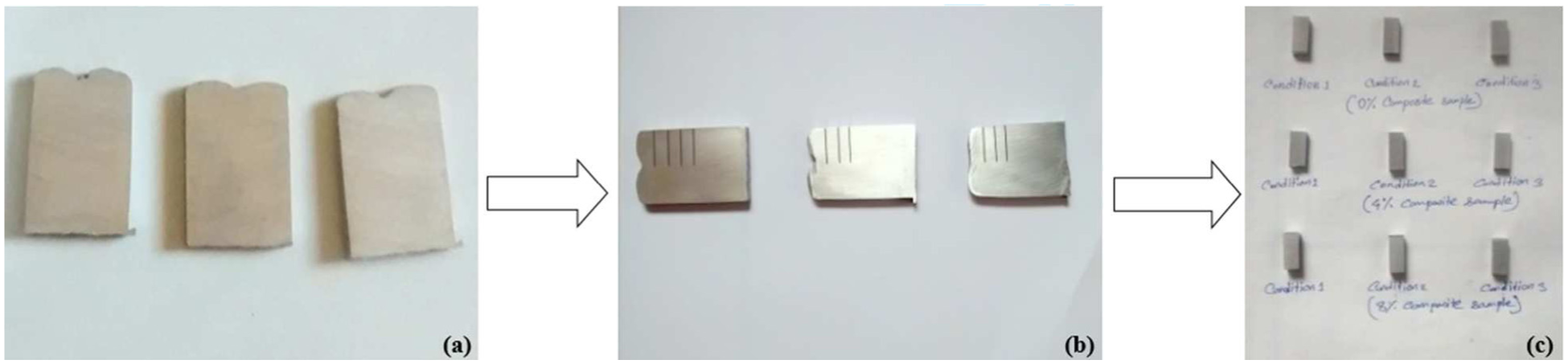
(a) Al6061/fly ash composites sample for WEDM, (b) Set of machined sample and (c) Sample for measuring Ra.
Experimental procedure
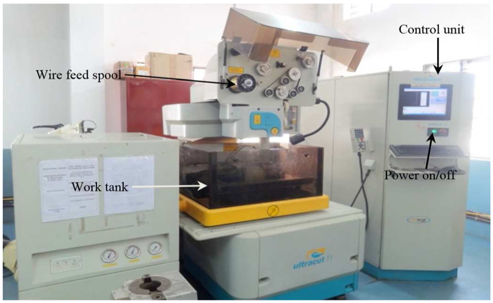
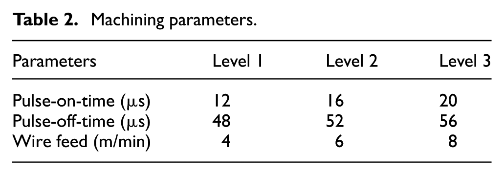
The machining experiments on the prepared composites have been performed in a computer numeric controlled (CNC) wire electrical discharge machine (M/S Electronica Machine Tools, Ltd) as shown in Figure 7. Deionised water was used as the dielectric fluid for the experiment. For machining, brass wire was selected as the electrode material, and the diameter of the wire was approximately 0.25 mm. The spark gap maintained between wire and specimen was approximately 0.002–0.005 mm. The prepared three composite samples (0%, 4% and 8%) with 5-mm thickness were polished by a set of emery papers to make the samples ready for machining. The preset length of the slot was set to 15 mm for each machining cut at different process parameters of the WEDM. Each of the machine parameters such as pulse-on-time (TON), pulse-off-time (TOFF) and wire feed varied at three levels as listed in Table 2.
CNC Electronica WEDM machine.
Machining parameters.
Results and discussion
Microstructure and interface
The microstructure attributes to the overall performance of a composite. However, particle size, particle shape and variation of reinforcement affect the physical properties of the composite materials. Microstructural investigations were performed on the prepared composites employing the X-ray diffraction (XRD) analysis and scanning electron microscopy (SEM) analysis. The SEM micrographs of the prepared AA6061/fly ash AMCs with different weight fractions reinforced (0%, 4% and 8%) are shown in Figure 8(a)–(c), respectively.
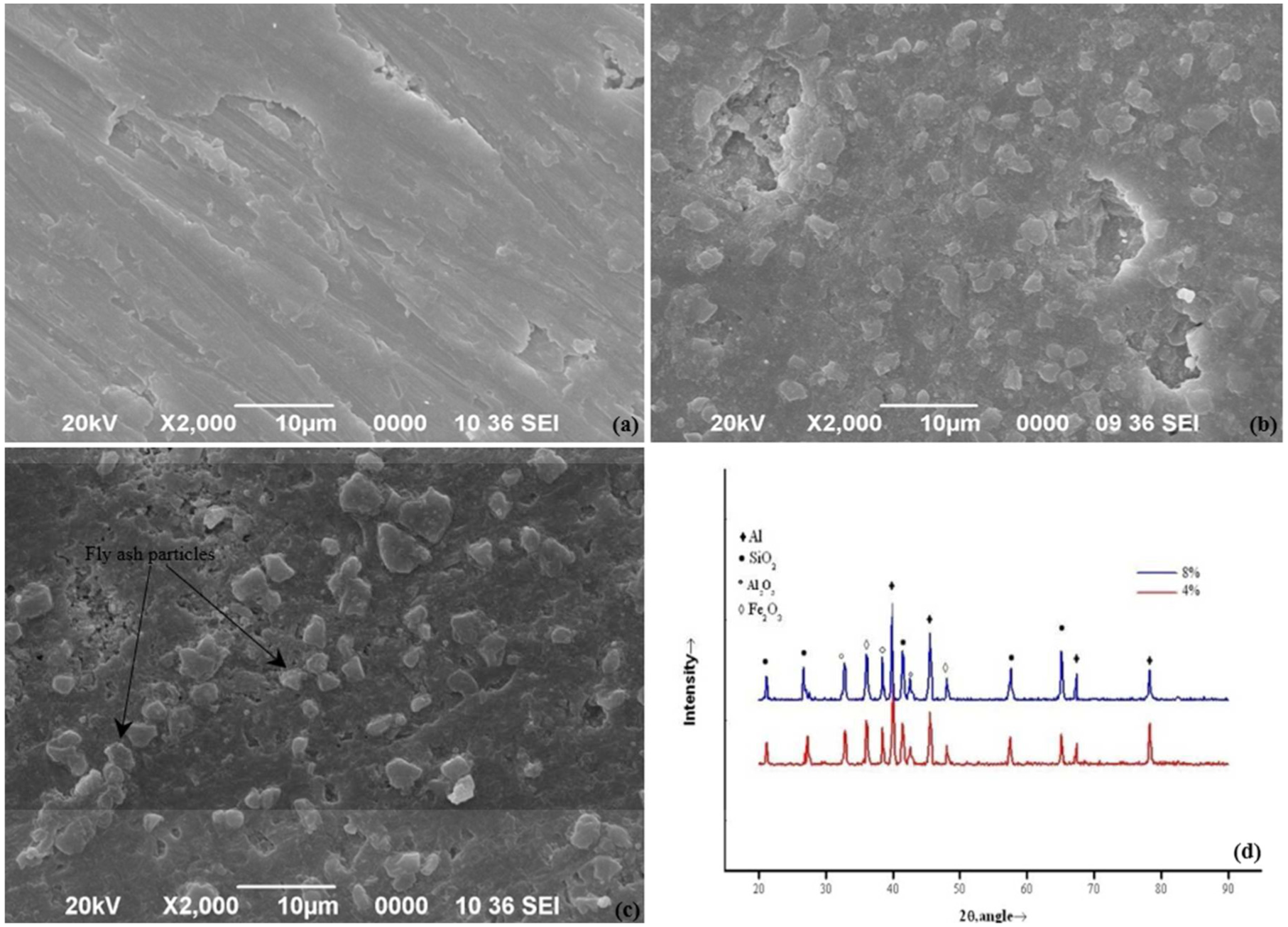
SEM micrograph of Al6061/fly ash composite: (a) 0 wt%, (b) 4 wt%, (c) 8 wt% and (d) XRD pattern of the prepared composites.
The micrographs reveal that the fly ash particles are uniformly distributed in the alloy matrix, and the dispersion increases as the quantity of the fly ash particles increases. The presence of voids, discontinuous phases and slag inclusion were not seen in the micrographs, which is evident that the selected compocasting method has the capacity to maintain the quality of casting.
The XRD spectra of the prepared composites are shown in Figure 8(d). The diffraction peaks of Al, SiO2, Al2O3 and Fe2O3 recognized as the major constituents of fly ash and aluminium alloy are clearly observed. So, it is evident that the integrity of the fly ash reinforcement is preserved during casting, and there is no occurrence of any interfacial reaction between fly ash content and matrix alloy material. However, the formation of intermetallic compounds due to interfacial reaction is caused due to degradation of the mechanical as well as tribological properties of the composite. But the compocasting process has successfully avoided these kinds of intermetallic compounds. David et al. 33 reported that the processing temperature of compocasting is considerably low compared to stir casting which is insufficient to initiate interfacial reactions. Compocasting route to fabricate AMCs helps to suppress the interfacial reactions.
Machining characteristics
Effect of the pulse-on-time on cutting speed
The pulse-on-time varies at three levels: 12, 16 and 20 µs. The peak current and wire feed are kept constant at 12 A and 4 m/min. It is evident from Figure 9 that the cutting speed increases with the increasing pulse-on-time for all the three composite samples. With increasing pulse-on-time, more material removal takes place due to increasing duration of sparking. However, unreinforced AA6061 alloy composite exhibited the highest cutting speed compared to both the reinforced composites. It is due to the fact that the fly ash particles are thermally and electrically nonconductive in nature, and therefore, the presence of fly ash reduces melting and vapourization of the composites. As a result, it obstructs the cutting speed during machining process. Also, there is no significant difference found in cutting speed between 4 and 8 wt% fly ash–reinforced composites.
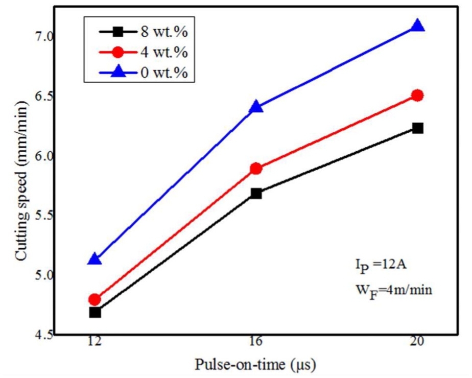
Variation of cutting speed with respect to pulse-on-time for different weight fractions of fly ash.
Effect of the pulse-on-time on kerf width
Figure 10 plots the kerf width versus the pulse-on-time for the various weight fractions of fly ash–reinforced composite materials. It reveals that as the pulse-on-time increases, the kerf width of the composites also increases, since the discharge energy of the machining surface is high. The narrowest kerf width is found in reinforced composites where it becomes thinner as the fly ash content is increased. It indicates that the thermally and electrically nonconductive fly ash particulates barricade the machining process compared to the conductive AA6061 aluminium alloy. These results may be attributed to the fact that the thermal conductivity and the electrical conductivity of the reinforced composites are lower than the unreinforced AA6061 alloy and so that high melting point of fly ash particles has required much more thermal energy per unit volume to melt the reinforced composite than that of the unreinforced alloys. The measured kerf width of the prepared composites specimens for different weight fractions of cenosphere contents are shown in Figure 11(a)–(c).
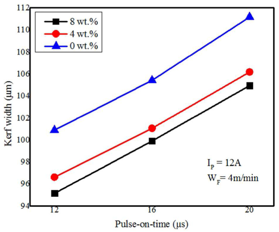
Variation of kerf width with respect to pulse-on-time for different weight fractions of fly ash.
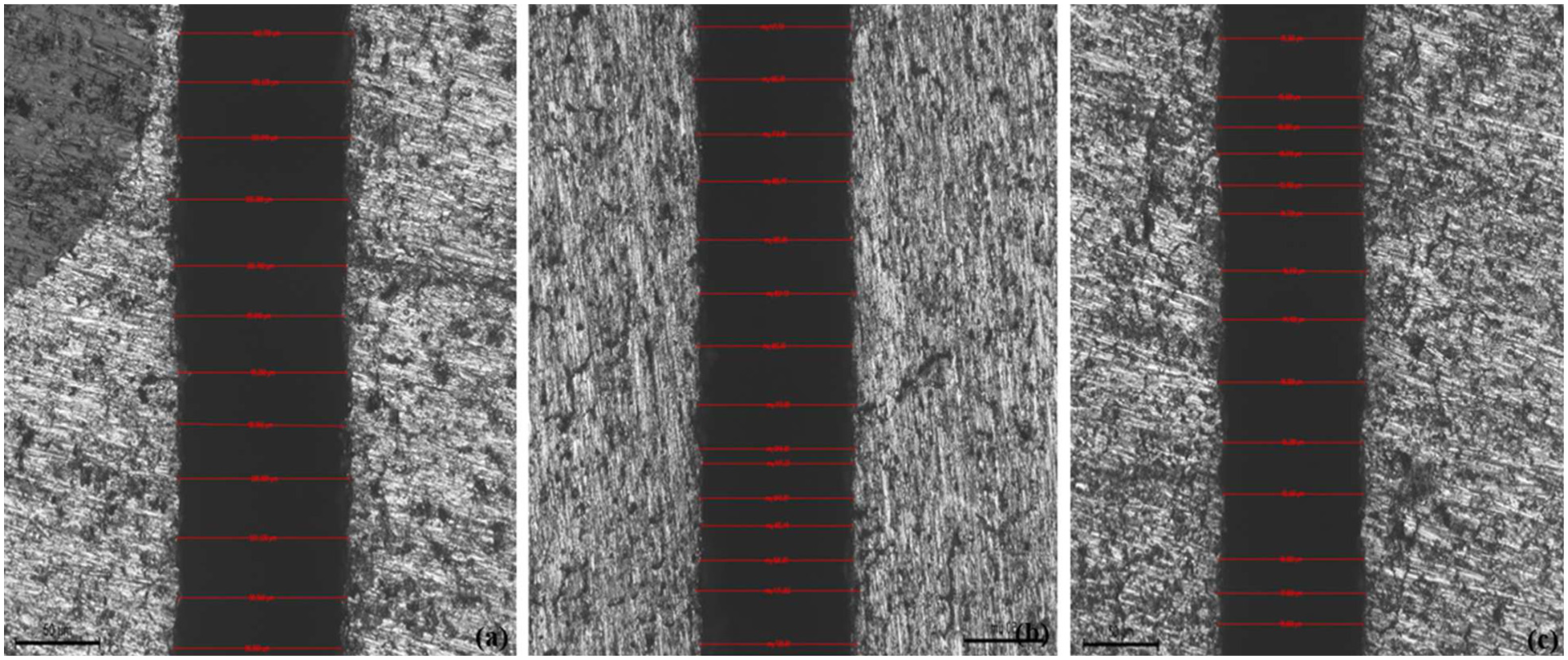
Measured kerf width of the prepared composite samples: (a) 0 wt%, (b) 4 wt% and (c) 8 wt%.
Effect of the pulse-on-time on surface roughness
Figure 12 plots the surface roughness against pulse-on-time for various weight fractions of fly ash–reinforced AA6061 alloy composites. It has been observed from the figure that, with the increase in pulse-on-time, the roughness of the machined surface of the composites increases due to the increased size of the craters produced on the machined surface, which results in the deterioration of surface integrity. However, the experimental results show that the 0 wt% fly ash/AA6061 composite provided the finest surface, and the 8 wt% fly ash/AA6061 composite exhibited the roughest surface. It is thus implied that fly ash particles of the composite protruded on machined surface and created poor surface integrity.
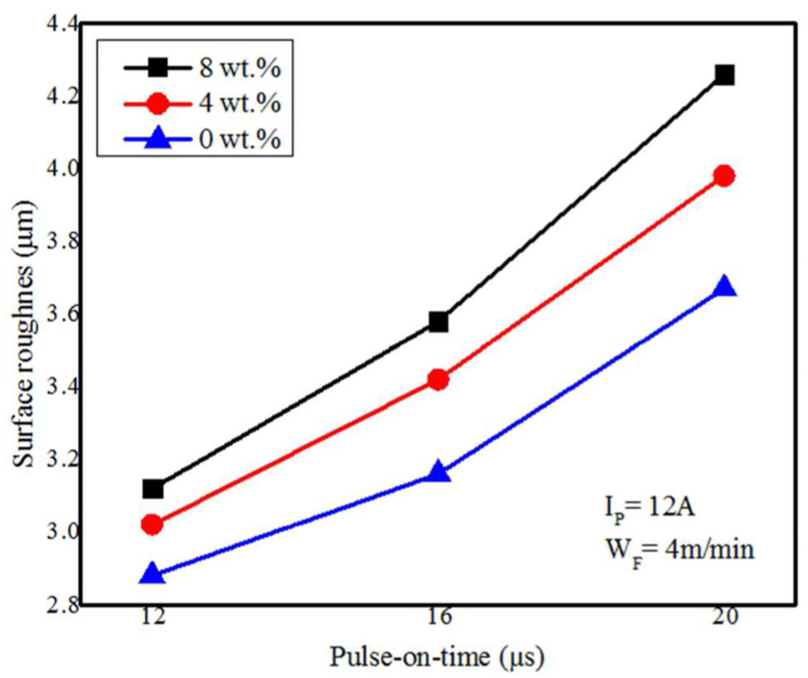
Variation of surface roughness with respect to pulse-on-time for different weight fractions of fly ash.
Effect of the pulse-off-time on cutting speed
The pulse-off-time varied at three levels: 48, 52 and 56 µs. The peak current and wire feed are kept constant at 12 A and 4 m/min. Figure 13 plots the cutting speed versus the pulse-off-time for the various weight fractions of fly ash–reinforced composite materials. It is evident from the graph that the cutting speed decreases with the increasing pulse-off-time for all the three composite samples due to the fact that on increasing the time gap between the two consecutive sparks, the process of erosion of material becomes slower. However, 8 wt% fly ash/Al (6061) has exhibited slowest cutting speed due to the presence of the utmost fly ash content in the composite and that impeded the erosion process during machining.
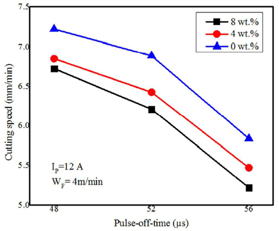
Variation of cutting speed with respect to pulse-off-time for different weight fractions of fly ash.
Effect of the pulse-off-time on kerf width
Figure 14 plots the kerf width versus the pulse-off-time for the various weight fractions of fly ash–reinforced composite samples. It is found from Figure 15 that the kerf width decreases with the increasing pulse-off-time for all the three composite samples. When the pulse-off-time is high, the discharge energy of the machining surface is low, which creates very shallow craters, and because of this, the kerf width is less at higher value of pulse-off-time. It was observed that the composites exhibits narrower kerf profile as the percentage of fly ash content increases in the composites.
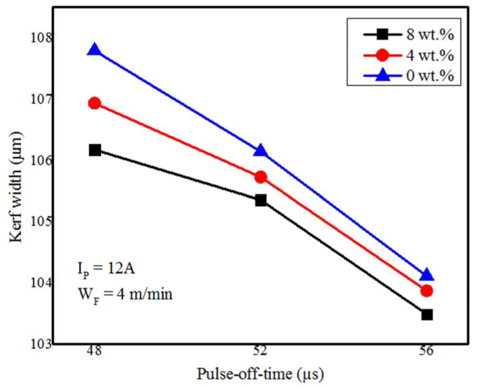
Variation of kerf width with respect to pulse-off-time for different weight fractions of fly ash.
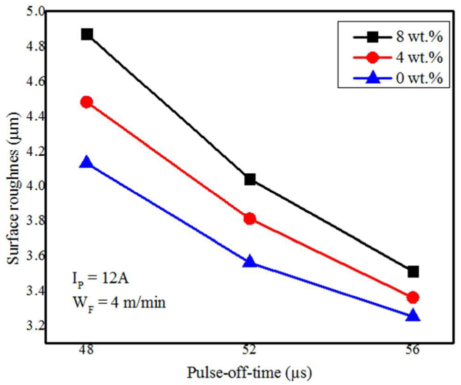
Variation of surface roughness with respect to pulse-off-time for different weight fractions of fly ash.
Effect of the pulse-off-time on surface roughness
Figure 15 plots the surface roughness versus the pulse-off-time for the various weight fractions of fly ash–reinforced composite samples. From Figure 15, it is seen that as the pulse-off-time increases, the roughness of the machined surface decreases. This is because, at high pulse-off-time, cooling time and flushing time will increase, which tends to spill out comparatively more amount of debris through the machining zone, avoiding the re-solidification of the molten material on the machine surface and thereby reducing the surface roughness. 50 Nevertheless, as the fly ash content increases in the composite, it exhibits more roughness on the machining surface. It is because during higher pulse-off-time, the insulating phase (fly ash) is dislodged after the melting of the surrounding matrix. Hence, the resulting craters are produced comparatively with more roughness on the machining surface of the composites.
Effect of the wire feed on cutting speed
The wire feed varied at three levels: 4, 6 and 8 m/min. The peak current, pulse-on-time and pulse-off-time are kept constant at 12 A, 20 µs and 52 µs, respectively. Figure 16 depicts the plots of cutting speed versus the wire feed for the various weight fractions of fly ash–reinforced composites. It is found that there is no significant influence of wire feed on cutting speed for all the three composite specimens. Hence, it is recommended to keep the wire feed in a medium level so as to reduce the wastage of wire, as higher feed causes more wire consumption as well as more cost of machining.
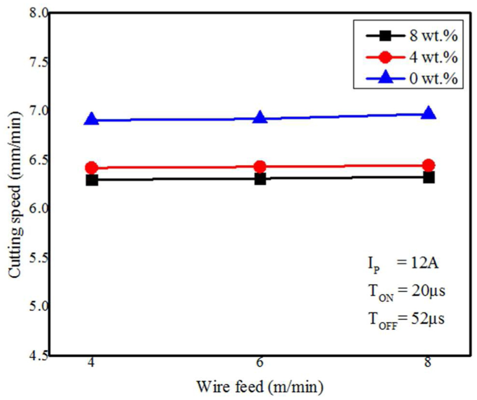
Variation of cutting speed with respect to wire feed for different weight fractions of fly ash.
Effect of the wire feed on kerf width
Figure 17 shows the plots of kerf width against the wire feed for the various weight fractions of fly ash–reinforced AMCs. It has been noticed from the figure that as the wire feed increases, the kerf width also increases; this is because as the wire feed increases more machining is done on the same area leading to more material removal, thus increasing the kerf width.
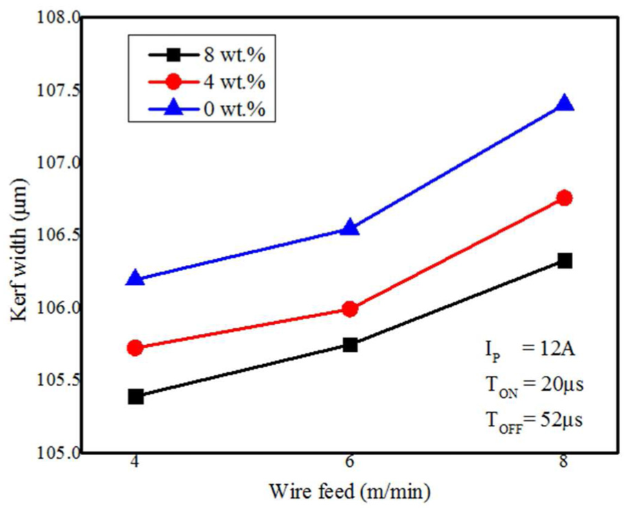
Variation of kerf width with respect to wire feed for different weight fractions of fly ash.
Effect of the wire feed on surface roughness
The plots of surface roughness versus the wire feed for the various weight fractions of cenosphere-reinforced AMCs are depicted in Figure 18. It was obtained from the figure that the surface roughness increases with the increase in wire feed, but the trend is almost linear which means the effect is very negligible.
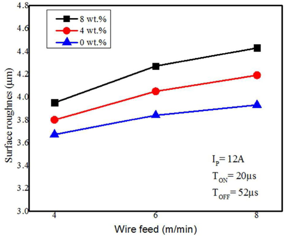
Variation of surface roughness with respect to wire feed for different weight fractions of fly ash.
Higher smoothness and fine-machined surface can be obtained at unreinforced AA6061 alloy composite (0 wt%) as shown in Figure 19(a), and as the percentage of fly ash content increases in the composites (4% and 8%), it offers more rough surface as shown in Figure 19(b) and (c) under same machining conditions.
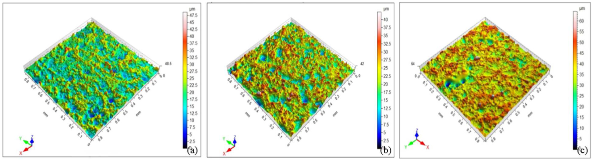
Generated 3D optical surface of the machined surface for various weight fractions of fly ash content AMCs: (a) 0 wt%, (b) 4 wt% and (c) 8 wt%.
Conclusion
Fly ash–reinforced AA6061 aluminium alloy composites were successfully fabricated using compocasting process, and machinability study of the prepared composites was conducted in WEDM machine:
There was no formation of any intermetallic compounds due to interfacial reaction, and the fly ash particles were uniformly distributed in the AMCs. It is evident that the selected compocasting route has successfully avoided the common casting defects of AMCs like interfacial transition, agglomerated phenomenon of reinforced particles and existing voids and cracks on the microstructure of the composites.
The incorporation of the cenosphere particles into semi-solid aluminium alloy attributed to improve wettability, and the fly ash particles were thermodynamically stable at that semi-solid temperature. Therefore, there was no requirement of any external wettability reagent and degasser compound in compocasting method and, consequently, the overall cost of fabrication was reduced.
Pulse-on-time and pulse-off-time have the most significant effects on the machining performance of the prepared composites in WEDM. However, wire feed is found to be the least significant among the three parameters affecting the machining performance.
It was found experimentally that on increasing the pulse-on-time, the cutting speed increases, whereas on increasing the pulse-off-time, the cutting speed decreases, for all the three machined composites. Nevertheless, Al (6061)/fly ash/0% composite exhibited the highest cutting speed than the two composites of Al (6061)/fly ash reinforced (4 and 8 wt%).
Surface texture of the machined surface shows that as the pulse-off-time increases, the surface roughness decreases. It is because that as the pulse-off-time increases, the cooling time and the flushing time also increase which tend to sweep away the debris from the machining surface. However, increasing of fly ash particles in composite is affected on the machined surface and it becomes rougher. This is because the insulating phase (fly ash) is dislodged after melting of the surrounding alloy matrix.
As the percentage of fly ash content increases in the composites, it exhibits narrower kerf profile, and it sustains for all the process parameter conditions. This is because high melting point of fly ash particles has required much more thermal energy per unit volume to melt the reinforced composite than that of the unreinforced composite.
The wire feed does not have any significant influence on the cutting speed for all the prepared composites. However, the kerf width and the surface roughness increase with increase in wire feed, but the effect is very small as compared to the other two parameters.
Footnotes
Acknowledgements
The authors are grateful to the Central Instruments Facility, IIT Guwahati and SAIC, Tezpur University, Assam, India, for providing the facility. They also thank the Department of Production Engineering, NIT Agartala, Tripura, India, for providing necessary support in conducting the experiments.
Declaration of conflicting interests
The author(s) declared no potential conflicts of interest with respect to the research, authorship and/or publication of this article.
Funding
The author(s) received no financial support for the research, authorship and/or publication of this article.